1
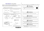
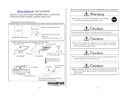
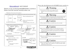
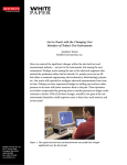
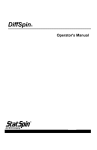
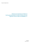
user’s manual 書 Please obey the following to the OLYMPUS micro cantilevers Thank you for purchasing OLYMPUS Micro cantilever. Please read this manual carefully before use. Warning Use protective eye glasses when handling to avoid damage to the eyes from breakage of the cantilever <Explanation of the each part of the products> chips. Cantilever chips in a plastic case are included in the envelope with manual and spec sheet. Caution Manual and Spec sheet Label Inside Please handle our cantilevers carefully because they are fragile. Plastic pack (blue colored) Plastic case (Cantilevers are in the case) Envelope for transportation Cantilever chips are contained in the plastic case (Tac carrier) Cantilever chips Adhesive sheet Case (Tac carrier) Upside Down side Cantilevers are tip-side-up as viewed in the case. Case Label Tape Case (closed) Case (open) Magnified illust. Case label BL-AC40TS-C2 Products name Lot Number Cantilever Cantilever chip (substrate) Caution Do not drop or shake the cantilever case. Even when the cantilever chips are contained in the cantilever case, the cantilevers may break if the case is handled roughly or jarred. Caution It is recommended that precautions be taken to prevent damage to the cantilever tips from electrostatic discharge. Caution Be sure to store the cantilevers at room temperature and moderate humidity. 110 Caution 0.09 Inspection stamp One cantilever is elongated from the side of round shoulders of the chip. - 1e - When discarding, please obey the laws and regulations in your country and/or your company. These cantilever are made of silicon, silicon nitride, gold and chromium. - 2e - Special feature of OLYMPUS Micro cantilever (BL-AC40TS-C2, BioLever mini) 1 1. 40 micron-long short cantilever This cantilever probe is designed for AC mode AFM measurements in liquid. The cantilever has been reduced to the minimum practical size for the optical beam deflection sensors in most commercially available AFM. This small cantilever has a nominal spring constant of 0.1 N/m, with a resonant frequency of approximately 25 kHz in water (or 110 kHz in air). The higher frequency in liquid allows faster imaging of soft biological samples, and the short lever give a higher lever sensitivity with optical beam deflection sensors. 2. Sharp tip The tip apex is sharp with tip radius of 10 nm (Ave.). The sharp apex will contribute to your high resolution measurements. The tip apex is made of silicon with a tetrahedral shape, ideal for achieving a point terminated tip. The apex is further sharpened with our exclusive sharpening process. The tip is a two-stage probe. Whole tip height is 7 micron and the effective tip height is 3.5 micron, longer than the tips of Olympus OMCL-TR/RC series. The long tip makes it possible to measure relatively large samples like bio cells. 1) Please prepare the followings before using OLYMPUS cantilevers. 2) To gain a better understanding of how cantilevers and chips are connected, cantilevers should be inspected under the microscope. 1) Work environment :Clean bench (Use of an electrical charge neutralizer of ionizer is recommended.) 2) For hazard avoidance :Protective eye glasses 3) For cantilever treatment:Tweezers (Use of anti-electrostatic discharge mat and a wrist band is recommended.) 4) For inspection :Stereo microscope 2 Please handle our cantilevers carefully because they are fragile. Caution 4. Gold reflex coating Gold/Chromium showing high reflection is employed as the reflex-coat material. Good S/N ratio can be expected in optical deflection sensing. See the specification sheet of OLYMPUS Micro cantilevers at the last page of this manual. Table of contents page 4e 1 Preparation 2 Open the case 4e 3 Picking up the cantilever chip from the case 4e 4 Tetrahedral tip in two stage structure 5e 5 Trouble-shooting guide 6e 6 Tips for better measurements 9e 7 Information 10e 8 Specification 1s - 3e - Open the case Caution 3. Pre-separated Chips The chips offered in tac carrier case, are separated in advance. The chips can be used in AFM as soon as the case is opened. 5. Small auto-fluorescence Auto-fluorescence light from the silicon nitride cantilever is lessened comparing to Olympus OMCL-TR/RC series silicon nitride cantilever. In AFMs combined with a fluorescence optical microscope, the less auto-fluorescent cantilever doesn’t obscure the light from the fluorescently-stained samples of interest. It also makes the cantilever alignment to the point of interest easy. Preparation It is recommended that precautions be taken to prevent damage to the cantilever tips from electrostatic discharge. 1) It is recommended that the cantilever case be opened in a clean environment like a clean bench in order to avoid the cantilever being contaminated. Handling under an ionizer is recommended. 2) Avoid wearing clothes like woolen sweaters, fleece etc that give off the static electricity when handling the cantilever cases and chips. Use of an anti-electrostatic mat and wrist band is preferable. 3) In opening the case, put the plastic case label-side down on a desk. The cantilevers are tip-side-up as viewed in the case. 4) Open the case. 3 Picking up the cantilever chip from the case Caution Avoid any contact with the cantilevers when you pull up the cantilever tip from the case. 1) Pick up the chip by the long side with the tweezers and mount it in the AFM. - 4e - 4 Tetrahedral tip in two stage structure A two stage structure is employed in this probe. (see left illustration) The head of the probe tip is made of silicon and tetrahedral in shape. The foot of the probe tips is also made of silicon, but covered with a silicon nitride film. There is a discontinuity in the probe shape midway between base and apex. The measurable sample height therefore limited to the height of the tip (3.5 micron). As can be seen in the left illustration, a tetrahedral tip is located near the triangular end of the cantilever. When observing the cantilever from the reflex side, a triangular pocket can be seen near the free end of the cantilever, marking the base of the tetrahedral tip. Operators can therefore easily locate the tip position relative to samples under optical microscope observation by finding the center of the triangular pocket. This makes alignment of the tip with sample very easy in AFMs, combined with optical microscopes. The tip profile is symmetric with a half tip angle of 18 degrees macroscopically (see left below). The side tip profile is asymmetric with a tip angle of 35 degrees. When the cantilever chip is attached to a chip holder in your AFM with an angle, about 10 degrees, the asymmetry is improved (see right below). The apex of the tetrahedral tip becomes sharper due to an oxide sharpening process. The tip angle in the final few hundred nano meter of the apex, is about 15 to 25 degrees (see below). When you set your samples to your instrument, please consider the unique shape of the tetrahedral tip, that is ‘good symmetry’, when viewing from front side and choose the direction of the sample. When measuring long grooves, you can get an idea of what angle of the cut will be quickly by aligning the cantilever along the grooves and scanning across at right angles against grooves (see below). 5 Trouble-shooting guide Situations as described below may arise when using this type of cantilever. Scan line profile Case 1: I tried optimizing imaging parameters first in air before. However good parameter values cannot be found and the cantilever oscillated. Scan line profile Front view Side view - 5e - Solution: From the beginning, try to optimize the measurement condition in water, e.g., sensor optics, cantilever sensitivity, I-gain, P-gain and frequency tuning. Selecting a smaller oscillation amplitude of cantilever for AC mode AFM measurement may gives better images because the tip is sharp and the cantilever is shorter than conventional cantilevers. - 6e - Case 2: When adjusting light spot position on the photo detector of AFM sensor head, SUM value indicating total incident light to the sensor, was small and rose to only 3 volts. Eight volts can usually be expected with cantilever with a reflex metal coating. Solution: As far as we examined, most commercially available AFMs display a SUM value of 3 to 4 volts even in the light spot shines center of the cantilever. This is due to the small size of the cantilever which is as large as the light spot. Try to adjust the focus of the sensor optics again. The adjustment might improve the SUM value. If possible, the adjustment should be done in the same environment as that of measurements. The chip is 0.3 mm thick. If you have used different type of cantilever chips before, for instance with a chip thickness of 0.5 mm, the spot may be out of focus on the cantilever. If possible, adjusting the focus of the spot in the focal depth direction might the improve SUM value. Case 3: The SUM value changes gradually with time. Solution: The spot position may have moved with time because of thermal drift in your AFM equipment. After the equipment is switched-on, allow some time for thermal equilibration and a stable instrument. Case 4: I have used this tip to image a standard flat grating pattern. However, the images has a high degree of curvature, with the center of the image appearing brighter (higher) and sinking down at the edge of the image. Solution: With using AFM equipments with a sensor head supported by a tripod mechanism, a cantilever chip-shoulder might contact to the sample surface before the cantilever itself contacts. This is due to use of short cantilever in the AFM which the sensor head. The position of the spot on the cantilever should be adjusted as shown in the diagram left below. If the spot is positioned at the extreme end of the cantilever, the laser may scatter, thereby reducing the total incident light on the photo detector, leading to a small SUM value. - 7e - Avoid rotation of the chip substrate in your chip holder. The cantilever chips should aligned straight in the cantilever chip holder. In clipping the chip, the chip should slide ahead a little than usual to avoid contact of the holder to the sample. If your chip holder uses L-shape wire for clipping a chip, the corner of the wire may hang over the clipping wire bar after repeat use. A cantilever chip in a chip holder Then, adjust the level of the AFM sensor head in the AFM and make the AFM sensor head and scanner parallel. In this procedure, use of a small water-leveling bottle is effective. It is important to minimize the tilt, especially in the transverse direction across the cantilever axis. - 8e - Case 5: By placing a piece of paper in front of the photo detector of my AFM sensor head for studying the position and the shape of the sensor light, several interference light spots are observed. Those spots align in the direction corresponding to the transverse direction of the cantilever axis. Solution: Adjust the optics of the AFM sensor to locating the primary spot to the center of the photo detector. 2) Merit of low thermal noise cantilevers Cantilevers vibrate a little in water due to Brownian motion noise. Such noise should be minimized in force curve measurements for research of folding mechanism of DNAs, proteins etc. Small size cantilevers show small Brownian motion noise and give good signal noise ratio in the measurements. 3) Merit of small auto-fluorescence cantilevers In AFM measurements of biological samples, AFM combined with a fluorescent optical microscope is useful. After recognizing fluorescently-stained samples with the optical microscope, a cantilever probe would locate to a point of interests on the sample. Conventional silicon nitride cantilevers sometimes obstruct fluorescent optical microscopy of the sample because of the large auto-fluorescent light generated from the cantilever. This cantilever probe has a far lower auto-fluorescence output which will not obscure your fluorescent sample. 7 Information Please contact following if you have any question on this user’s manual. 6 Tips for better measurements 1) Merit of using cantilevers with a high resonant frequency Resonant frequencies of the cantilevers decrease by factor of 4 to 5 in water because of the water around the cantilevers. The lower resonance cantilever forces operators to wait for a long time to acquire an image due to a slow scan speed. BL-AC40TS-C2 with a high resonant frequency of 25 kHz (typ.) in water while being soft with spring constant of 0.1 N/m, enables the fast imaging of biological samples in water. Of course, scan speed is deeply dependent on the performance of the scanner and measurement samples. If a small and robust scanner with high resonant frequency is used, one can expect 5 Hz line scan frequency in AC mode AFM measurements in water, while 0.5 Hz with conventional silicon nitride cantilevers. In observing a sparse biological sample on a substrate, a large area, e.g., a 10 micron square, is scanned to locate a target of the sample. High-speed cantilevers are timesaving device for AFM measurement particularly in the aiming procedure. Even with a slight improvement in the scan speed by a factor of two or three, high-speed cantilevers are worth using because they reduce the time required for observing such large areas before increasing magnification. High-speed cantilever is a key to improve efficiency of the study in your lab.. - 9e - OLYMPUS CORPORATION Microtechnology R&D Division 2-3 Kuboyama-cho Hachioji-shi Tokyo 192-8512 Japan email : [email protected] Please access to the web page of OLYMPUS micro cantilevers. http://www.olympus.co.jp/probe Ver.2.0 June 22, 2009 OLYMPUS CORPORATION - 10e -