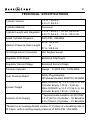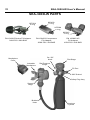
1
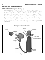
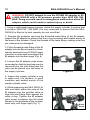
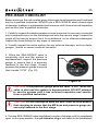
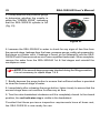
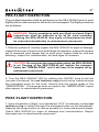
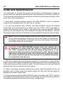
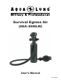
Survival Egress Air
(SEA-3000LW)
User's Manual
Rev 09/14
2
SEA-3000LW User's Manual
COPYRIGHT NOTICE
This user's manual is copyrighted, all rights reserved. It may not, in whole or
in part, be copied, photocopied, reproduced, translated, or reduced to any
electronic medium or machine readable form with out prior consent in writing
from Aqua Lung America, Inc.
©2014 Aqua Lung International
SEA-3000LW User’s Manual PN 103642
You can contact a Technical Advisor via e-mail at:
[email protected]
[email protected]
[email protected]
TRADEMARK NOTICE
Aqua Lung® is a registered trademark of
Aqua Lung America, Inc.
Warnings, Cautions and Notes:
Pay special attention to information provided in Warnings, Cautions
and Notes that are ac c ompanied by one of these symbols:
A WARNING indicates a procedure or situation that, if not avoided,
could result in serious injury or death to the user.
A CAUTION indicates any situation or technique that could
cause damage to the product and could subsequently result in
injury to the user.
A NOTE is used to emphasize important points, tips and reminders.
3
TABLE OF CONTENTS
General Precautions and Warnings............................................................. 4
Product Description....................................................................................... 6
Preparation and Setup................................................................................... 7
General Filling Procedures....................................................................... 7
Filling Methods for SEA-3000LW............................................................. 9
Filling SEA-3000LW with a SCUBA Fill Adapter...................................... 9
Filling SEA-3000LW with a Compressor Fill Adapter............................ 13
Filling SEA-3000LW with a HP Fill Adapter........................................... 16
Filling SEA-3000LW with a MRS III (Mobile Refill Station).................... 19
Adjusting Mouthpiece Position............................................................... 23
Changing the SEA-3000LW Mouthpiece............................................... 24
Pre-Issue Checklist...................................................................................... 25
Pre-Flight Inspection................................................................................... 27
Post-Flight Inspection................................................................................. 27
Care and Maintenance................................................................................. 28
Inspection and Service................................................................................ 30
Warranty Information.................................................................................. 30
Technical Specifications............................................................................. 31
SEA-3000LW Parts....................................................................................... 32
Notes............................................................................................................. 33
4
SEA-3000LW User's Manual
GENERAL PRECAUTIONS AND WARNINGS
The SEA-3000LW is intended for use only as an emergency device
to assist a crew member or passenger in making an emergency
egress from a submerged aircraft. Due to its limited air volume, it
is not intended for use while scuba diving or egressing from depths
greater than 45 ft/ 13.5 m.
Before using the SEA-3000LW, it is important to receive in-water
survival training which simulates an emergency egress situation.
You must also learn basic principles and techniques for breathing
compressed air underwater. Use of the SEA-3000LW without proper
training is dangerous and can result in serious injury or death.
Visual inspection and factory prescribed service for the SEA-3000LW
must be performed at least once every two years by a factory trained
and qualified service technician. Repair, service and visual inspection
must not be attempted by untrained or unqualified personnel.
DO NOT attempt to overfill the SEA-3000LW beyond 3000 PSI / 206
BAR at 70ºF/ 21ºC. Doing so may seriously weaken the cylinder and
cause it to rupture, resulting in serious injury or death.
DO NOT fill or use the SEA-3000LW if it has been exposed to
extreme heat exceeding 250º F / 121º C or open flame. Instead,
discharge the cylinder completely and return it to a qualified
technician for inspection and possible hydrostatic testing.
The SEA-3000LW is designated compatible for use only with normal,
atmospheric, compressed air (21% oxygen and 79% nitrogen by volume).
DO NOT attempt to fill with other gases, including pure oxygen or air
which has been enriched with oxygen exceeding 21% in content. Failure
to observe this warning may result in serious injury or death due to fire
and explosion or the serious deterioration and failure of the equipment.
5
DO NOT apply any type of petroleum-based lubricant, such as
household oil or motor oil to any part of the SEA-3000LW. The
SEA-3000LW does not require any lubrication under normal
circumstances, except that which is performed during annual
inspection and service by a factory trained service technician.
DO NOT apply any type of aerosol spray to the 3000LW. Doing
so may cause permanent damage to certain plastic components,
including the second stage housing.
During training exercises, it is important to ensure that the 3000LW
is always pressurized whenever it is submerged in order to prevent
the entrance of water into the system. Whenever the system has
been completely emptied of air underwater, it is important to return
the 3000LW as soon as possible to a qualified technician for visual
inspection and any necessary service before attempting to refill it.
It is important to fill the 3000LW only with dry, filtered air with a
water vapor content that does not exceed -65°F / -53ºC dew point.
Excess water vapor in the air can cause ice to form inside the
3000LW and interfere with the operation of the system at colder
temperatures.
6
SEA-3000LW User's Manual
PRODUCT DESCRIPTION
SEA-3000LW Components (Fig. 1)
•
SEA-3000LW balanced diaphragm first stage with integral fill port, dial pressure
gauge, safety plug assembly, 360 degree swivel and On / Off knob. Black
aluminum components are utilized on first stage for a low reflective signature.
•
20 in (50.8 cm) or 27 in (68.6 cm) braided medium pressure (MP) hose with tool
free swivel allows for quick and easy exchange of the second stage when needed.
•
Ergonomic low volume balanced second stage with indexable mouthpiece
allows for variable regulator orientation.
•
Light weight aluminum cylinder 1.5 cf (42.5 L) or 2.0 cf (56.6 L), 3000 PSI
/ 206 BAR.
Component Identification
On / Off
Knob
Mouthpiece
Cover
Indexable
Mouthpiece
First Stage
Dial Pressure
Gauge
Fill Port
360º Swivel
Safety Plug Assy
Second
Stage
Braided
Hose
Aluminum
Cylinder
Figure 1
7
PREPARATION AND SETUP
The purpose of this manual is to familiarize you with the correct setup, filling,
inspection and maintenance of the SEA-3000LW.
The SEA-3000LW is packaged fully assembled and ready to use after it has
been filled with air. Before using it, however, it is very important to carefully read
and understand the procedures outlined in this manual for filling the unit and
performing a preflight inspection.
General Filling Procedures
NOTE: The average duration of air supply listed in the Technical
Specifications section of this manual is based on a completely
full SEA-3000LW aluminum cylinder, filled to 3000 PSI / 206 BAR
with a volume of 1.5 cf (42.5 L) or 2.0 cf (56.6 L) of air. It is strongly
recommended that the SEA-3000LW be filled to 3000 PSI / 206 BAR
(cold fill), in order to provide maximum breath volume.
1. Before attempting to fill the SEA-3000LW, ensure that the fill adapter and
first stage are completely dry – especially in the area surrounding the fill port.
2. The SEA-3000LW is configured with a 3000 PSI/ 206 BAR aluminum cylinder.
Examine the cylinder markings to verify it is rated for a fill pressure of 3000 PSI/
206 BAR and has a current visual inspection (Fig. 2).
NOTE: The SEA-3000LW 1.5 cf (42.5 L) and 2.0 cf (56.6 L) aluminum
cylinders do not require hydrostatic re-testing. (Fig. 2).
Month & Year
of Manufacture
(Hydro Date)
Maximum Fill
Pressure
Figure 2
8
SEA-3000LW User's Manual
WARNING: DO NOT attempt to fill the SEA-3000LW if the cylinder
markings indicate that it is assembled with a non standard cylinder
rated for a different fill pressure than 3000 PSI / 206 BAR. Doing so
may result in rupture or explosion in the event of fire or overfilling.
Instead, immediately return the unit to a qualified technician and
do not use under any circumstances.
3. Turn the valve handwheel clockwise
until it is completely closed. To ensure
the valve is closed, check to see if the
red indicator ring is visible in the
handwheel (Fig. 3).
4. Depress the second stage purge
button to ensure that the system is
completely depressurized.
"OFF"
POSITION
Red indicator
ring visible
Figure 3
5. Unscrew the fill port cap from the
fill port (Fig. 4).
6. Closely inspect the fill port opening
to ensure that no debris, residue or
moisture is present.
Figure 4
CAUTION: If moisture is found to be present inside the fill port
opening, this indicates that water may have entered the SEA3000LW first stage and cylinder. DO NOT fill or attempt to use
the SEA-3000LW until it has received complete inspection and
any required service by a qualified technician.
9
WARNING: DO NOT attempt to loosen or remove the first stage hose
fitting or safety plug assembly plug under any circumstances. Doing
so could result in a dangerous malfunction of the SEA-3000LW which
could result in serious injury or death.
Filling Methods for SEA-3000LW
1. SCUBA cylinder with SCUBA fill adapter (PN 108325).
2. Compressor with compressor fill adapter (PN 100656).
3. Compressor with HP fill adapter (PN 102865).
4. MRS-III (Mobile Refill Station) with HP fill adapter (PN 102865).
Filling SEA-3000LW with a SCUBA Fill Adapter
NOTE: The SEA-3000LW system does not include a SCUBA fill adapter.
This adapter (PN 108325) may be purchased separately (Fig. 5).
O-Ring
Figure 5
CAUTION: Do not attempt to fill the SEA-3000LW directly from a
supply cylinder unless you have received the necessary training
and authorization to do so. If done incorrectly, this procedure
poses certain hazards which may cause severe injury or death.
CAUTION: The SEA-3000LW dial pressure gauge is for reference
only. Use the fill system gauge to indicate accurate cylinder pressure.
10
SEA-3000LW User's Manual
WARNING: DO NOT attempt to use the SCUBA fill adapter to fill
a SEA-3000LW with a fill pressure greater than 3000 PSI /206
BAR. Doing so could result in a dangerous malfunction of the fill
adapter, which could result in serious injury or death.
1. Using a calibrated pressure gauge, check the supply cylinder to ensure that
it contains 3000 PSI / 206 BAR. It is very important to ensure that the SEA3000LW is filled to its total capacity but not overfilled.
2. Remove the protector cap from the threaded male fitting of the fill adapter.
Inspect the fill adapter to ensure that the o-ring is present and seated evenly at
the base of the threads. Check the threads of the male fitting, making sure they
are clean and not damaged.
3. Fit the threaded male fitting of the fill
adapter into the fill port and turn clockwise by hand until snug. DO NOT apply
a wrench or otherwise overtighten the
fill adapter into the first stage (Fig. 6).
4. Loosen the fill adapter yoke screw
as needed so that the dust cap can be
removed from the inlet fitting and the
yoke can be placed over the valve of
the supply cylinder.
Figure 6
5. Inspect the supply cylinder o-ring
to make sure it is present, in good
condition and seated evenly in the
supply cylinder valve.
6. While supporting the SEA 3000-LW
with one hand, place the yoke of the
fill adapter over the cylinder valve to
align the inlet fitting flush against the
valve o-ring. Tighten the fill adapter
yoke screw clockwise into the small
dimple on the backside of the cylinder
valve only until finger tight (Fig. 7).
Bleed
Screw
Figure 7
11
7. Close the bleed valve screw on the fill adapter by turning it clockwise
until finger tight (Fig. 7).
WARNING: DO NOT attempt to fill the SEA-3000LW from a supply
cylinder that has a fill pressure greater than 3000 PSI / 206 BAR. Doing
so may weaken or damage the safety plug assembly and cylinder.
NOTE: The SEA-3000LW will fill with the valve handwheel in the
completely closed position (red indicator ring visible). In this position
the pressure gauge will not register psi. This is not recommended.
8. While holding the first stage and
fill adapter secure, turn the valve
handwheel counter-clockwise until it
is completely open. When the handwheel is in the open position, the red
indicator ring is not visible (Fig. 8).
9. Support the cylinder with one hand
and very slowly turn the supply cylinder
valve handwheel counter-clockwise
to open and begin filling. As the SEA3000LW cylinder begins to fill, make
sure the dial pressure gauge shows that
the cylinder is filling properly.
"ON"
POSITION
Red indicator
ring not visible
Figure 8
NOTE: Always fill the cylinder as slowly as possible by turning the
handwheel of the supply valve slowly to control the rate of fill. Rapid
filling will generate heat and will result in an incomplete fill after the
cylinder cools. If the cylinder is warm to the touch afterward, the fill
rate was too rapid.
10. When at least two minutes have elapsed and air can no longer be heard
flowing from the supply cylinder into the SEA-3000LW, turn the supply cylinder
valve completely open.
12
SEA-3000LW User's Manual
11. To conserve the limited air supply of the SEA-3000LW, it is strongly recommended
that you perform a pre-issue inspection of the second stage purge while it is connected
to the supply cylinder as follows:
a. Briefly depress the purge button to ensure that sufficient airflow is provided
to clear the second stage of water.
b. Immediately after releasing the purge button, listen closely to ensure
that the second stage does not continue to flow any air.
12. While holding the first stage and fill adapter secure, turn the SEA-3000LW
valve handwheel clockwise until it stops and the red indicator ring is visible.
Turn the handwheel of the supply cylinder valve clockwise until completely closed.
13. Hold the second stage purge button depressed until airflow can no longer
be heard from the second stage and the MP hose between the first and second
stages is completely depressurized.
14. Open the bleed valve screw on the fill adapter to relieve the line pressure.
15. While supporting the SEA-3000LW cylinder with one hand, turn the yoke
screw of the fill adapter counter-clockwise to loosen until the complete system
can be lifted off and removed from the supply cylinder valve.
16. While holding the SEA-3000LW secure, turn the fill adapter counter-clockwise
at the fitting to loosen and remove from the first stage. Replace the dust cap over
the inlet fitting and tighten the yoke screw finger tight. Replace protector cap on
the threaded male fitting of the fill adapter.
17. Thread the fill port cap into the fill port until finger tight.
18. When charging is complete, store the fill adapter in a clean area.
13
Filling SEA-3000LW with a Compressor Fill Adapter
NOTE: The SEA-3000LW system does not include a compressor fill
adapter. This adapter (PN 100656) may be purchased separately (Fig. 9).
O-Ring
O-Ring
Figure 9
WARNING: DO NOT attempt to use the compressor fill adapter (PN
100656) to fill a SEA-3000LW with a fill pressure greater than 3000
PSI /206 BAR. Doing so could result in a dangerous malfunction of
the fill adapter, which could result in serious injury or death.
CAUTION: Do not attempt to fill the SEA-3000LW directly from
a compressed air filling station unless you have received
the necessary training and authorization to do so. If done
incorrectly, this procedure poses certain hazards which may
cause severe injury or death.
CAUTION: The SEA-3000LW dial pressure gauge is for reference
only. Use the fill system gauge to indicate accurate cylinder pressure.
14
SEA-3000LW User's Manual
1. Remove the protector cap from the threaded male fitting of the fill adapter.
Inspect the fill adapter to ensure that the o-ring is present and seated evenly
at the base of the threads. Check the threads of the male fitting, making sure
they are clean and not damaged. Inspect the o-ring in the groove on the fill
block end of the adapter, making sure it is seated evenly and is not damaged.
2. Fit the threaded male fitting of the fill adapter into the fill port of the first stage
and turn clockwise by hand until snug. DO NOT apply a wrench or otherwise
overtighten the fill adapter.
3. Loosen the yoke screw on the compressor fill yoke as needed so that the
yoke can be placed over the block of the fill adapter.
4. While supporting the SEA-3000LW
with one hand, place the yoke over the
block of the fill adapter to align the inlet
fitting flush against the fill block o-ring.
Tighten the yoke screw clockwise into
the small dimple on the backside of the
fill adapter until finger tight (Fig. 10).
5. Close the bleed valve screw on
the compressor fill yoke by turning it
clockwise until finger tight.
Figure 10
WARNING: DO NOT attempt to fill the SEA-3000LW from a compressor
or air supply where the regulated pressure exceeds 3000 PSI / 206 BAR.
Doing so may weaken or damage the safety plug assembly and cylinder.
NOTE: The SEA-3000LW will fill with the valve handwheel in the
completely closed position (red indicator ring visible). In this position
the pressure gauge will not register psi. This is not recommended.
15
6. While holding the first stage and fill
adapter secure, turn the SEA-3000LW
valve handwheel counter-clockwise
until it is completely open. When the
handwheel is in the open position, the
red indicator ring is not visible (Fig. 11).
"ON"
POSITION
Red indicator
ring not visible
Figure 11
7. Ensure that the SEA-3000LW is supported and turn the compressor valve
very slowly counter-clockwise until it is slightly open to fill the cylinder with
approximately 500 PSI / 34.5 BAR. Turn the compressor valve shut and wait
45-60 seconds before proceeding to fill the cylinder any further. Repeat this
procedure to fill the cylinder very slowly in small increments of 500 PSI / 34.5
BAR or less, until it is filled to 3000 PSI / 206 BAR. Make sure the dial pressure
gauge shows that the cylinder is filling properly.
NOTE: Always fill the cylinder as slowly as possible by turning the
handwheel of the supply valve slowly to control the rate of fill. Rapid
filling will generate heat and will result in an incomplete fill after the
cylinder cools. If the cylinder is warm to the touch afterward, the fill
rate was too rapid.
8. To conserve the limited air supply of the SEA-3000LW, it is strongly
recommended that you perform the following pre-issue inspection of the
second stage purge while the SEA-3000LW is connected to the compressor
fill yoke and pressurized via the fill adapter:
a. Briefly depress the purge button to ensure that sufficient airflow is provided
to clear the second stage of water.
b. Immediately after releasing the purge button, listen closely to ensure
that the second stage does not continue to flow any air.
16
SEA-3000LW User's Manual
9. While holding the first stage and fill adapter secure, turn the SEA-3000LW
valve handwheel clockwise until it stops and the red indicator ring is visible.
Turn the compressor valve completely closed.
10. Hold the second stage purge button depressed until air flow can no longer
be heard from the second stage and the MP hose is depressurized.
11. Open the bleed valve screw on the compressor fill yoke to relieve the
line pressure.
12. While holding the SEA-3000LW cylinder, loosen the yoke screw on the
compressor fill yoke as needed and remove it from the fill adapter. Return the
compressor fill yoke to its storage location.
13. While holding the SEA-3000LW secure, turn the fill adapter counter-clockwise
at the fitting to remove it from the first stage. Replace protector cap on the threaded
male fitting of the fill adapter.
14. Thread the fill port cap back into the fill port until finger tight.
15. When charging is complete, store the fill adapter in a clean area.
Filling SEA-3000LW with a HP Fill Adapter
NOTE: The SEA-3000LW system does not include a HP fill adapter.
This adapter (PN 102865) may be purchased separately (Fig. 12).
O-Ring
Figure 12
17
NOTE: The HP fill adapter (PN 102865) may be used to fill 3000
PSI /206 BAR cylinders. (Fig. 12).
CAUTION: Do not attempt to fill the SEA-3000LW directly from
a compressed air filling station unless you have received
the necessary training and authorization to do so. If done
incorrectly, this procedure poses certain hazards which may
cause severe injury or death.
CAUTION: The SEA-3000LW dial pressure gauge is for reference
only. Use the fill system gauge to indicate accurate cylinder pressure.
1. Remove the protector cap from the threaded male fitting on the fill adapter.
Inspect the fill adapter to ensure that the o-ring is present and seated evenly at
the base of the threads. Check the threads of the male fitting, making sure they
are clean and not damaged.
2. Fit the threaded male fitting of the fill
adapter into the fill port of the first stage
and turn the adapter nut clockwise
by hand until snug. DO NOT apply a
wrench or otherwise overtighten the
fill adapter. (Fig. 13).
Bleed Valve
Screw
Adapter
Nut
Figure 13
3. Close the bleed valve screw on the fill adapter by turning it clockwise until
finger tight.
WARNING: DO NOT attempt to fill the SEA-3000LW from a compressor
or air supply where the regulated pressure exceeds 3000 PSI / 206 BAR.
Doing so may weaken or damage the safety plug assembly and cylinder.
18
SEA-3000LW User's Manual
NOTE: The SEA-3000LW will fill with the valve handwheel in the
completely closed position (red indicator ring visible). In this position
the pressure gauge will not register psi. This is not recommended.
4. While holding the first stage and fill
adapter secure, turn the SEA-3000LW
valve handwheel counter-clockwise
until it is completely open. When the
handwheel is in the open position, the
red indicator ring is not visible (Fig. 14).
"ON"
POSITION
Red indicator
ring not visible
Figure 14
5. Ensure that the SEA-3000LW is supported and turn the compressor valve
very slowly counter-clockwise until it is slightly open to fill the cylinder with
approximately 500 PSI / 34.5 BAR. Turn the compressor valve shut and wait
45-60 seconds before proceeding to fill the cylinder any further. Repeat this
procedure to fill the cylinder very slowly in small increments of 500 PSI /
34.5 BAR or less, until it is filled to 3000 PSI / 206 BAR. Make sure the dial
pressure gauge shows that the cylinder is filling properly.
NOTE: Always fill the SEA-3000LW as slowly as possible by turning
the handwheel of the supply valve slowly to control the rate of fill.
Rapid filling will generate heat and will result in an incomplete fill after
the cylinder cools. If the cylinder is warm to the touch afterward, the
fill rate was too rapid.
6. To conserve the limited air supply of the SEA-3000LW, it is strongly recommended
that you perform the following pre-issue inspection of the second stage purge while
the SEA-3000LW is pressurized and connected to the fill adapter:
a. Briefly depress the purge button to ensure that sufficient airflow is provided
to clear the second stage of water.
b. Immediately after releasing the purge button, listen closely to ensure
that the second stage does not continue to flow any air.
19
7. While holding the first stage and fill adapter secure, turn the SEA-3000LW
valve handwheel clockwise until it stops and the red indicator ring is visible.
Turn the compressor valve completely closed.
8. Hold the second stage purge button depressed until air flow can no longer
be heard from the second stage and the MP hose is depressurized.
9. Open the bleed valve screw on the fill adapter to relieve the line pressure.
10. While holding the SEA-3000LW cylinder, turn the adapter nut counter-clockwise
to loosen and remove from the first stage. Replace protector cap on the threaded
male fitting of the fill adapter. Return the fill adapter to its storage location.
11. Thread the fill port cap back into the fill port until finger tight.
Filling SEA-3000LW with a MRS III (Mobile Refill Station)
WARNING: The MRS III (Mobile Refill Station) has the capacity
to fill the SEA-3000LW to a maximum fill pressure of 3000 PSI /
206 BAR using a HP fill adapter (PN 102865).
CAUTION: Do not attempt to fill the SEA-3000LW directly
from a MRS III Mobile Refill Station unless you have received
the necessary training and authorization to do so. If done
incorrectly, this procedure poses certain hazards which may
cause severe injury or death.
CAUTION: The SEA-3000LW dial pressure gauge is for reference
only. Use the fill system gauge to indicate accurate cylinder pressure.
20
SEA-3000LW User's Manual
The MRS-III is a self-contained Mobile Refill Station with an onboard supply
of approved breathing air pressurized up to 3000 psi. The MRS-III is designed
to fill up to two Aqua Lung SEA-3000LW units simultaneously to the operating
pressure of 3000 PSI / 206 BAR. The following instructions are the same for
filling one unit or two (Refer to the MRS-III instruction book for more detailed
instructions) (Fig. 15).
Figure 15
1. Verify that both panel-mounted fill valves on the MRS-III are closed (clockwise).
2. Open the valves on the MRS-III supply cylinders and verify that the supply
pressure gauge on the panel reads 3000 PSI / 206 BAR.
3. Verify that the regulated pressure gauge on the MRS-III panel reads 3000
PSI / 206 BAR.
4. Unscrew the fill adapter from its mounting point and install the fill port plug in
its place for safekeeping pending re-installation. Inspect the fill adapter to ensure
that the o-ring is present and seated evenly at the base of the threads. Check
the threads of the male fitting, making sure they are clean and not damaged.
5. Place the SEA-3000LW in the blast tube.
21
6. Install the threaded male fitting of
the fill adapter into the fill port of the
first stage and turn the adapter nut
clockwise only by hand until snug.
DO NOT apply a wrench or otherwise
overtighten the fill adapter. (Fig. 16).
Bleed Valve
Screw
Adapter
Nut
Figure 16
7. Close the bleed valve screw on the fill adapter by turning it clockwise until
finger tight.
NOTE: The SEA-3000LW will fill with the valve handwheel in the
completely closed position (red indicator ring visible). In this position
the pressure gauge will not register psi. This is not recommended.
8. Turn the SE A-3000LW valve
handwheel counter-clockwise until it
is completely open. When the handwheel is in the open position, the red
indicator ring is not visible (Fig. 17).
Repeat process for second cylinder.
"ON"
POSITION
Red indicator
ring not visible
Figure 17
9. Very slowly open the MRS-III panel-mounted fill valve (counter-clockwise) that
corresponds to the fill hose being used and fill the cylinder with approximately 500
PSI / 34.5 BAR. Turn the panel-mounted fill valve shut and wait 45-60 seconds
before proceeding to fill the cylinder any further. Repeat this procedure to fill the
cylinder very slowly in small increments of 500 PSI / 34.5 BAR or less, until it
is filled to 3000 PSI / 206 BAR. Make sure the dial pressure gauge shows that
the cylinder is filling properly.
22
SEA-3000LW User's Manual
NOTE: Always fill the SEA-3000LW as slowly as possible by turning
the handwheel of the supply valve slowly to control the rate of fill.
Rapid filling will generate heat and will result in an incomplete fill after
the cylinder cools. If the cylinder is warm to the touch afterward, the
fill rate was too rapid.
10. To conserve the limited air supply of the SEA-3000LW, it is strongly recommended
that you perform the following pre-issue inspection of the second stage purge while
the SEA-3000LW is pressurized and connected to the MRS III:
a. Briefly depress the purge button to ensure that sufficient airflow is provided
to clear the second stage of water.
b. Immediately after releasing the purge button, listen closely to ensure
that the second stage does not continue to flow any air.
11. When the SEA-3000LW has cooled and is full, turn the SEA-3000LW valve
handwheel clockwise until it stops and the red indicator ring is visible. Close
the MRS-III panel mounted fill valve.
12. Hold the second stage purge button depressed until airflow can no longer
be heard from the second stage and the MP hose is depressurized.
13. Open the bleed valve screw on the fill adapter and vent the pressure from
the fill hose.
14. Disconnect the fill adapter from the SEA-3000LW by rotating the adapter nut
counter-clockwise.
15. Replace the fill port cap into the fill port of the SEA-3000LW unit and hand tighten.
16. When all filling operations are complete, close the valves on the MRS-III supply
cylinders. Firmly grasp one of the fill adapters, point in a safe direction and bleed
any remaining pressure from the system by slowly opening the corresponding
panel-mounted fill valve for that hose.
17. Close both panel-mounted fill valves and both bleed valve screws on the MRS-III.
18. Attach the fill adapters to the provided mounting brackets, close and securely
latch the MRS-III cover.
23
Adjusting Mouthpiece Position
The second stage incorporates a position keying feature that enables the user
to adjust orientation of the second stage body in relation to the mouthpiece. This
unique feature keeps the hose closer to the body and allows for more flexibility
in various cylinder-mounting configurations.
The mouthpiece-to-body default
position is horizontal which allows
the hose to route either to the right
or left of the regulator second stage.
The mouthpiece boss on the body is
hexagonally shaped, which allows the
mouthpiece to rotate to six different
positions (Fig. 18).
Hexagonal Mouthpiece Boss
Hexagonal Mouthpiece
Figure 18
WARNING: The mouthpiece clamp must always be installed
before returning regulator to service. Failure to install the clamp
will result in mouthpiece separating from regulator body during
deployment of regulator.
24
SEA-3000LW User's Manual
Changing the SEA-3000LW Mouthpiece
1. Mount SEA-3000LW cylinder in user
preferred position.
2. Remove the black clamp with side
cutters and discard (Fig. 19).
Figure 19
3. Rotate the mouthpiece to preferred
position (Fig. 20).
Figure 20
4. Install a new black clamp with the
clamp tab positioned in-line with the
center of the right bite-tab on the
mouthpiece. Since the mouthpiece is
of a lower profile design than standard
SCUBA-style mouthpieces the clamp
tab should be orientated in this manner
so that the clamp tab does not interfere
with the users lips (Fig. 21).
Figure 21
25
PRE-ISSUE CHECKLIST
Before each use, the unit must be given a thorough visual inspection and functional
test by a qualified technician. NEVER use a SEA-3000LW which shows signs
of damage, leakage or substandard performance until it has received inspection
and service from a qualified technician.
1. Carefully inspect the medium pressure hose to ensure it is securely connected
into its respective port on the first stage and onto the second stage. Inspect the
length of the hose to ensure that it is not blistered, cut or otherwise damaged.
Inspect the hose fittings for any signs of corrosion.
2. Visually inspect the entire system for any external damage, such as dents,
gouges, cracks or severe external corrosion.
3. While the SEA-3000LW valve is
completely shut and the system is
depressurized, inspect the pressure
gauge to ensure that it is securely
fastened to the first stage. Closely
examine the pressure gauge to ensure
that it reads “0 PSI” (Fig. 22).
“0 PSI”
Figure 22
CAUTION: If the pressure gauge does not read “0 PSI” when the
valve is shut and the system is depressurized, DO NOT attempt
to use the system until it has received inspection and service
from a qualified technician.
CAUTION: DO NOT attempt to open the SEA-3000LW valve without
first checking to ensure that the MP hose and pressure gauge are
securely fastened to the first stage.
4. Turn the SEA-3000LW valve handwheel counter-clockwise until it is completely
open. In the open position, the red indicator ring is not visible in the handwheel.
26
SEA-3000LW User's Manual
5. Closely examine the pressure gauge
to determine whether the needle is
within the “GREEN ZONE”, indicating
that the SEA-3000LW cylinder is full
(Fig. 23).
GREEN
ZONE
Figure 23
6. Immerse the SEA-3000LW in water to check for any signs of free flow from
the second stage, leakage from the hose, pressure gauge, safety plug assembly,
first stage or cylinder neck. If leakage is found, do not attempt to use the SEA3000LW until it has received service from a qualified technician. When complete,
remove the water from the SEA-3000LW 1st & 2nd stages and reinstall the
mouthpiece cover.
NOTE: If the second stage purge was checked during the filling procedure,
it is not necessary to repeat steps 7 & 8.
7. Briefly depress the purge button to ensure that sufficient airflow is provided
to clear the second stage of water.
8. Immediately after releasing the purge button, listen closely to ensure that the
second stage does not continue to allow any air flow.
9. Turn the valve handwheel clockwise until it is completely closed. In the closed
position, the red indicator ring is visible in the handwheel.
Provided that these pre-issue inspection requirements have all been met,
the SEA-3000LW is now ready for use.
27
PRE-FLIGHT INSPECTION
The pre-flight inspection shall be performed on the SEA-3000LW prior to each
flight by the air crew member to whom the unit is assigned. Pre-flight procedures
are as follows:
WARNING: Strict compliance with pre-flight and post-flight
inspections shall be adhered to by all air crew members
utilizing the SEA-3000LW. Any signs of discrepancies shall
be reported immediately to maintenance personnel.
1. With the system off, visually inspect the SEA-3000LW for signs of damage.
Inspect front cover, exhaust cover and fittings for tightness. Inspect for tamper
dot (if command uses tamper dot) on front cover. Inspect hose for cuts and
blistering. Inspect for contamination, dirt and signs of corrosion.
CAUTION: Do not press the purge button when the SEA-3000LW
is on. Purging of the SEA-3000LW will deplete the pressure
below the “GREEN ZONE” and it will have to be topped off by
maintenance personnel.
2. Turn the SEA-3000LW “ON” by rotating the ON/OFF knob to the left
(counter-clockwise), the red indicator ring should not be visible through
the elongated holes on the knob. Ensure that the gauge reads in the
“GREEN ZONE”. If the gauge does not read in the “GREEN ZONE” report
discrepancy to maintenance personnel.
POST-FLIGHT INSPECTION
1. Upon completion of flight, turn handwheel “OFF” (clockwise), so that red
indicator ring is visible through the elongated holes on the handwheel.
Depress the purge button to relieve pressure in hose and second stage.
Check SEA-3000LW for signs of damage and contamination. Report
discrepancies to maintenance personnel.
28
SEA-3000LW User's Manual
CARE AND MAINTENANCE
It is important to provide the proper preventative maintenance in order to
ensure the best possible performance and reliability of the SEA-3000LW.
The following maintenance procedures should be performed routinely after
each use of the equipment.
1. After each in-water training session, the SEA-3000LW must be cleaned,
inspected and prepared for the next use or storage.
2. As soon as possible after training, the SEA-3000LW should be soaked
thoroughly for at least one hour in warm (not over 120ºF / 49ºC) tap water to
loosen and dissolve salt (if used in salt water) and mineral deposits. Before
soaking, turn the valve to the “ON” position to pressurize the system. This will
best prevent the entrance of moisture into the system through the second stage.
NOTE: Due to the light weight aluminum first stage, the SEA-3000LW
is not recommended for continuous use in salt water. The aluminum
first stage is susceptible to galvanic corrosion and needs to be rinsed
thoroughly after use in salt water.
CAUTION: If the SEA-3000LW cylinder does not contain air, it
is important to ensure that the valve is completely turned to
the “OFF” position and the second stage purge button is not
depressed while the system is submerged or wet. Moisture may
otherwise be allowed to enter the valves and the cylinder, which
will require that the system be returned to a qualified technician
for inspection and service.
3. After the system has been properly soaked, it is important to rinse the first
stage, the second stage mouthpiece and the openings in the second stage front
cover with a pressurized stream of water. This will remove the salt and mineral
deposits that were loosened during soaking.
4. When it has been properly soaked and rinsed, wipe the system as dry as
possible with a clean towel and gently shake the first and second stage to
dislodge any water inside them.
5. Check to ensure that the SEA-3000LW valve is turned to the “OFF” position
and depress the purge button of the second stage to ensure that the system is
completely depressurized before storing or transporting.
29
6. Due to the possibility of fire and exposure to extreme heat, the SEA-3000LW
must be stored either completely full or completely empty. If the system is
exposed to fire while partially filled, the cylinder wall may rupture before the
internal pressure becomes great enough to burst the safety plug assembly. For
this reason, Aqua Lung recommends that the cylinder be completely emptied
and the valves kept shut to prevent the entrance of moisture before storing the
system for an indefinite period.
WARNING: DO NOT store the SEA-3000LW partially filled. Doing so
may prevent the safety plug assembly from functioning properly
in the event of fire or exposure to extreme heat. This may cause
the cylinder to rupture or explode, possibly resulting in severe
injury or death.
7. Store the SEA-3000LW completely dry, in a clean equipment box or sealed
inside a plastic bag. When possible, avoid storing it where it may be exposed to
extreme heat or an electric motor, which produces ozone. Prolonged exposure
to extreme heat, ozone, chlorine and ultraviolet rays can cause premature
degradation of rubber parts and components and must be prevented.
8. When transporting the SEA-3000LW, take the necessary precautions to
ensure that it is surrounded by a protective cushion to prevent undue shock
or impact.
9. Do not use any type of solvent or petroleum based substances to clean or
lubricate any part of the regulator. Do not expose the regulator to aerosol spray,
as some aerosol propellants attack or degrade rubber and plastic.
30
SEA-3000LW User's Manual
INSPECTION AND SERVICE
1. It cannot be assumed that the SEA-3000LW is in good working order on
the basis that it has received little use since it was last serviced. Remember
that prolonged or improper storage can still result in internal corrosion and/or
deterioration of o-ring seals and valve springs.
2. It is imperative that you obtain factory prescribed service for your SEA3000LW at least once every two years from a qualified technician, including a
visual inspection of the cylinder and complete overhaul of the first and second
stage regulators. Your SEA-3000LW may require this service more frequently,
depending on the amount of use it receives and the environmental conditions
it is used in.
3. If the SEA-3000LW is used for training purposes in salt water, chlorinated
or silted fresh water, it will require complete overhaul and factory prescribed
service every three to six months or whenever it is suspected that moisture has
entered the system. Use in chlorinated swimming pool water will accelerate the
deterioration of most rubber components and require more frequent service
than in other typical conditions.
4. DO NOT attempt to perform any disassembly or service of your SEA-3000LW.
Doing so may cause the system to dangerously malfunction. All service must
be performed by a qualified technician.
WARNING: Do not attempt to loosen or remove the first stage hose
fitting, gauge or safety plug assembly under any circumstances.
Doing so could result in a dangerous malfunction of the SEA3000LW, which could result in serious injury or death.
OBTAIN FACTORY PRESCRIBED SERVICE FOR YOUR SEA-3000LW AT
LEAST ONCE EVERY TWO YEARS. YOUR PERSONAL SAFETY AND THE
MECHANICAL INTEGRITY OF YOUR SEA-3000LW DEPEND ON IT.
WARRANTY INFORMATION
For detailed information on product warranties, please refer to the Terms and
Conditions Section of the Aqua Lung Military and Professional Buyers Guide.
The buyers guide can be viewed or downloaded from the Aqua Lung Military
and Professional website at www.aqualung.com/militaryandprofessional
31
TECHNICAL SPECIFICATIONS
Cylinder Volume
1.5 cf / 42.5 L
2.0 cf / 56.6 L
Cylinder Material
Aluminum
Cylinder Length with Regulator
1.5 cf / 42.5 L - 10 in / 25.4 cm
2.0 cf / 56.6 L - 12 in / 30.5 cm
Rated Cylinder Pressure
3000 PSI / 206 BAR
20 in / 50.8 cm
Medium Pressure Hose Length
or
27 in / 68.6 cm
First stage Hose Connection
360 Degree Swivel
Regulator First Stage
Balanced Diaphragm
Regulator Second Stage
Balanced Second Stage
Pressure Indicator
Gauge
Over Pressure Relief
Safety Plug Assembly
HP Module Mounted, 5000 PSI / 345 BAR
System Weight
Duration of Air Supply
0-3000 PSI / 0-206 BAR
SEA-3000LW w/ 1.5 cf (42.5 L) AL
Cylinder Empty 1.78 lb. / 0.80 kg
SEA-3000LW w/ 2.0 cf (56.6 L) AL
Cylinder Empty 1.95 lb. / 0.88 kg
**Approximate breaths at 20 FSW:
1.5 cf (42.5 L) Cylinder - 18 Breaths
2.0 cf (56.6 L) Cylinder - 21 Breaths
**Based on an average breath volume of 1.5 liters at a breathing rate of
10.5 bpm, with a starting supply pressure of 3000 PSI / 206 BAR.
32
SEA-3000LW User's Manual
SEA-3000LW PARTS
820120
o-ring
957004
o-ring
957004
o-ring
820312
o-ring
PN 108325 Scuba Fill Adapter
3000 PSI / 206 BAR
PN 100656 Compressor
Fill Adapter
3000 PSI / 206 BAR
On / Off
Knob
Mouthpiece
Cover
Indexable
Mouthpiece
PN 102865 HP
Fill Adapter
4500 PSI / 310 BAR
First Stage
Dial Pressure
Gauge
Fill Port
360º Swivel
Safety Plug Assy
Second
Stage
Braided
Hose
Aluminum
Cylinder
33
NOTES
34
SEA-3000LW User's Manual
NOTES
35
NOTES
Survival Egress Air 3000LW
(SEA-3000LW)
User’s Manual
2340 Cousteau Court • Vista, CA 92081
Phone (760) 597-5000 • Fax (760) 597-4900
www.aqualung.com/militaryandprofessional
©2014 Aqua Lung International