1
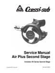
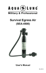
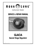
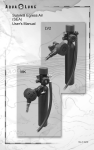
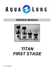
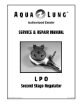
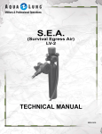
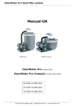
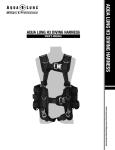
Helicopter Aircrew Breathing Device
(H.A.B.D.)
User’s Manual
Rev 04/11
2 H.A.B.D. User’s Manual
Copyright Notice
This owner’s manual is copyrighted, all rights reserved. It may not,
in whole or in part, be copied, photocopied, reproduced, translated,
or reduced to any electronic medium or machine readable form
without prior consent in writing from Aqua Lung America, Inc.
©2011 Aqua Lung International
H.A.B.D. Owner’s Manual
P/N 102897 - Rev. 04/11
Trademark Notice
Aqua Lung®, M.A.S.™, Conshelf ™, Micra ™ are registered
trademarks of Aqua Lung America, Inc.
Warnings, Cautions and Notes
Pay special attention to information provided in warnings, cautions,
and notes, that is accompanied by these symbols:
A WARNING indicates a procedure or situation that may
result in serious injury or death to the user.
A caution indicates any situation or technique that will
result in potential damage to the product.
A note is used to emphasize important points, tips, and
reminders.
H.A.B.D. User’s Manual 3
Contents
General Precautions & Warnings................................4
Preparation and Setup.................................................6
Filling Procedures - General.............................................6
Filling the H.A.B.D. From a SCUBA Cylinder...................8
Pre-Issue Inspection.......................................................10
Filling the H.A.B.D. From a Compressor........................12
Pre-Issue Inspection.......................................................13
Pre-Flight Inspection..................................................15
Post-Flight Inspection................................................16
Care & Maintenance...................................................17
Inspection & Service..................................................19
Technical Specifications............................................20
First-Stage Exploded Parts Schematic....................21
Second-Stage (left) Exploded Parts Schematic......22
Second-Stage (right) Exploded Parts Schematic....23
Notes...........................................................................24
4 H.A.B.D. User’s Manual
General Precautions and Warnings
The H.A.B.D. is intended for use only as an emergency device to assist aircrew members or passengers in making an
emergency egress from a submerged aircraft. Due to its
limited air volume, it is not intended for use while scuba diving or egressing from depths greater than 45 ft / 13.7 m.
Before using the H.A.B.D., it is important to receive in-water survival training which simulates an emergency egress
situation. You must also learn basic principals and techniques for breathing compressed air underwater. Use of
the H.A.B.D. without proper training is dangerous and can
result in serious injury or death.
Visual inspection and factory prescribed service for the
H.A.B.D. must be performed annually by a factory trained
and qualified service technician. Repair, service and visual inspection must not be attempted by untrained or unqualified personnel.
DO NOT attempt to overfill the H.A.B.D beyond 3,000 PSI
/ 206 BAR at 70˚F / 21˚C. Doing so may seriously weaken
the cylinder and cause it to rupture, resulting in serious
injury or death.
DO NOT fill or use the H.A.B.D. if it has been exposed to
extreme heat exceeding 250˚F / 121˚C or open flame. Instead, discharge the cylinder completely and return it to
a qualified technician for inspection and possible hydrostatic testing.
The H.A.B.D. is designated compatible for use only with normal,
atmospheric, compressed air (21% oxygen and 79% nitrogen
by volume). DO NOT attempt to fill with other gases, including pure oxygen or air which has been enriched with oxygen
exceeding 21% in content. Failure to observe this warning may
result in serious injury or death due to fire and explosion, the
serious deterioration and failure of the equipment.
DO NOT apply any type of petroleum-based lubricant, such
as household oil or motor oil to any part of the H.A.B.D. The
H.A.B.D. does not require any lubrication under normal circumstances, except that which is performed during annual inspection and service by a factory trained service technician.
H.A.B.D. User’s Manual 5
DO NOT apply any type of aerosol spray to the H.A.B.D.
Doing so may cause permanent damage to certain plastic
components, including the second-stage housing.
During training exercises, it is important to ensure that the
H.A.B.D. is always pressurized whenever it is submerged
in order to prevent the entrance of water into the system.
Whenever the system has been completely emptied of air
underwater, it is important to return the H.A.B.D. as soon
as possible to a qualified technician for visual inspection
and any necessary service before attempting to refill it.
It is important to fill the H.A.B.D. only with dry, filtered air
with a water vapor content that does not exceed -65˚F /
-54˚C dewpoint. Excess water vapor in the air can cause
ice to form inside the H.A.B.D., and interfere with the operation of the system at colder temperatures.
Component Identification
SCUBA fill adapter
First-Stage
with integrated
valve
First-Stage
with integrated
valve
Second-Stage
Second-Stage
Cylinder
Left-handed model.
Cylinder
Right-handed model.
6 H.A.B.D. User’s Manual
Preparation and Setup
The purpose of this manual is to familiarize you with the correct
setup, filling, inspection and maintenance of the H.A.B.D. (Helicopter Aircrew Breathing Device).
The H.A.B.D. (P/N 102800) is packaged fully assembled and ready to
use after it has been filled with air. Before using it, however, it is very
important to carefully read and understand the procedures outlined in
this manual for filling the unit and performing a pre-flight inspection.
Filling Procedures - General
NOTE: The average duration of air supply listed on page 20
of this manual is based on a completely full H.A.B.D. cylinder,
filled to 3,000 PSI/ 206 BAR with a volume of 1.5 cubic ft / 42.5
liters of air. It is strongly recommended that the H.A.B.D. be
filled to 3,000 PSI / 206 BAR (cold fill), in order to provide maximum breath volume.
1. Before attempting to fill the H.A.B.D., ensure that the fill adapter
and first-stage are completely dry - especially in the area surrounding the high pressure port.
2. Examine the cylinder markings to verify that it is rated for a fill
pressure of 3,000 PSI/ 206 BAR (See Fig. 1).
WARNING: DO NOT attempt to fill the H.A.B.D if the cylinder
markings indicate that it was assembled with a non-standard
cylinder rated for a different fill pressure than 3,000 PSI / 206
BAR. Doing so may result in rupture or explosion in the event of
fire or overfilling. Instead, immediately return the unit to a qualified technician and do not use under any circumstances.
Maximum Fill
Pressure
Month & Year
of Manufacture
Figure 1
Serial No.
H.A.B.D. User’s Manual 7
3. Examine the position of the “ON/OFF” indicator ring in relation
to the indicator pin to determine whether the valve is open or
shut. If necessary, turn the first-stage clockwise while holding
the cylinder secure only until it stops and the indicator pin is
positioned inside the aperture marked “OFF.” (See Fig. 2).
CAUTION: When turning the H.A.B.D. “ON /OFF“, over rotating can cause damage to the indicator pin.
Figure 2 - “OFF” position
4. Depress the second-stage purge button to ensure that the
system is completely depressurized.
5. Apply an 11/16” open-end wrench to the pressure gauge assembly, located between the HP port which contains the safety
disc assembly and the low pressure port which contains the LP
hose swivel (See Fig. 3). Turn the pressure gauge assembly
counter-clockwise to loosen and remove from the first-stage.
Figure 3 - Pressure gauge
6. Closely inspect the port opening to ensure that no debris, residue, or moisture is found to be present.
8 H.A.B.D. User’s Manual
CAUTION: If moisture is found to be present inside the port
opening, indicating that water may have entered the H.A.B.D.
first-stage and cylinder, DO NOT fill or attempt to use the
H.A.B.D. until it has received complete inspection and any required service by a qualified technician.
WARNING: Do not attempt to loosen or remove the firststage hose fitting or safety burst plug under any circumstances. Doing so could result in a dangerous malfunction of the H.A.B.D., which could result in serious injury
or death.
Filling the H.A.B.D. from a SCUBA Cylinder
NOTE: Most H.A.B.D. systems do not include a SCUBA fill
adapter. This adapter (PN 108325) may be purchased separately (Refer to page 5 for component identification).
1. Using a calibrated pressure gauge, check the supply cylinder
to ensure that it contains at least 2,800 PSI/ 193 BAR and less
than 3,100 PSI/ 214 BAR. It is very important to ensure that
the H.A.B.D. is filled to its total capacity, but not overfilled.
2. Remove the protector cap from the threaded nozzle of the fill
adapter. Inspect the nozzle to ensure the O-ring is present and
seated evenly at the base of the threads.
NOTE: The pressure gauge assembly may be placed inside
the cap to prevent loss or damage while filling the H.A.B.D.
3. Mate the threaded nozzle of the fill adapter into the open HP
port, and turn clockwise by hand until snug. DO NOT apply a
wrench or otherwise overtighten the fill adapter into the firststage.
4. Loosen the fill adapter yoke screw as needed so that the dust
cap can be removed from the inlet fitting and the yoke can be
placed over the valve of the supply cylinder.
5. While supporting the H.A.B.D. with one hand, place the yoke
of the fill adapter over the cylinder valve to align the inlet fitting
flush against the valve O-ring. Tighten the fill adapter yoke
screw clockwise into the small dimple on the backside of the
cylinder valve only until finger snug. (See Fig. 4).
H.A.B.D. User’s Manual 9
Figure 4 - Filling the H.A.B.D.
WARNING: DO NOT attempt to fill the H.A.B.D. from a supply cylinder which contains more than 3,100 PSI / 214 BAR.
Doing so may weaken and damage the safety burst plug
assembly and / or H.A.B.D. cylinder.
6. While holding the first-stage and fill adapter secure, turn the
H.A.B.D. cylinder counter-clockwise until a single click is felt
and the ON-OFF indicator pin can be sighted through the small
aperture marked “ON.” (See Fig. 6).
7. Support the H.A.B.D. cylinder with one hand, and slowly turn
the supply cylinder valve handwheel counter-clockwise to open
and begin filling.
8. When at least one minute has elapsed and air can no longer be
heard flowing from the supply cylinder into the H.A.B.D., turn the
supply cylinder valve completely open.
NOTE: Always fill the H.A.B.D. as slowly as possible by turning
the handwheel of the supply valve slowly to control the rate of
fill. Rapid filling will generate heat and will result in an incomplete fill after the cylinder cools. If the cylinder is warm to the
touch afterward, the fill rate was too rapid.
10 H.A.B.D. User’s Manual
Pre-Issue Inspection
1. To conserve the limited air supply of the H.A.B.D., it is strongly
recommended that you perform a pre-issue inspection of the
second-stage purge while it is connected to the supply cylinder
as follows:
a. Depress the purge button to ensure that sufficient airflow is
provided to clear the second-stage of water.
b. Immediately after releasing the purge button, listen closely
to ensure that the second-stage does not continue to flow
any air.
2. While holding the first-stage and fill adapter secure, turn the
H.A.B.D. cylinder clockwise until it stops and the indicator
pin is positioned inside the aperture marked “OFF.” Turn the
handwheel of the supply cylinder valve clockwise until shut.
3. Hold the second-stage purge button depressed until airflow can no
longer be heard from the second-stage and the LP hose between
the first and Second-Stages is completely depressurized.
4. While supporting the H.A.B.D. cylinder with one hand, turn the
yoke screw of the fill adapter counter-clockwise to loosen until
the complete system can be lifted off and removed from the
supply cylinder valve.
5. While holding the H.A.B.D. secure, turn the fill adapter counterclockwise at the fitting to loosen and remove from the first-stage.
Replace the dust cap over the inlet fitting and tighten the yoke
screw until finger snug.
H.A.B.D. User’s Manual 11
6. Remove the pressure gauge assembly from the protector cap
which is connected to the fill adapter. Place the protector cap
securely over the threaded nozzle of the fill adapter and set
aside. Examine the pressure gauge assembly to ensure that
the O-ring appears to be clean and dry, without any signs
of decay or damage and is seated evenly at the base of the
threads. If the O-ring appears to be in worn or damaged condition, it is important to obtain a new O-ring from a qualified
technician before attempting to use the H.A.B.D.
7. Examine the opposite side of the pressure gauge assembly
to ensure that it is completely clean and free of any debris or
signs of damage which may interfere with the movement of
the indicator pin.
8. Mate the threaded end of the pressure gauge assembly into
the open HP port and turn clockwise by hand until finger snug.
Apply an 11/16” open end wrench and tighten the pressure
gauge assembly until snug (approximately 20 in-lb / 2.26 Nm).
DO NOT overtighten.
9. While holding the first-stage secure, turn the H.A.B.D. cylinder
counter-clockwise until it stops and the indicator pin is positioned inside the aperture marked “ON.”
10.Immerse the H.A.B.D. in water to check for any signs of freeflow from the second-stage or leakage from the hose, pressure
gauge, safety disc assembly, first-stage or cylinder neck. If
leakage is found, do not attempt to use the H.A.B.D. until it
has received service from a qualified technician.
11.While holding the first-stage secure, turn the H.A.B.D. cylinder
clockwise until it stops and the indicator pin is positioned inside
the aperture marked “OFF.” Briefly depress the purge button
to depressurize the hose and ensure that sufficient airflow is
provided to clear the second-stage of water.
12 H.A.B.D. User’s Manual
Filling the H.A.B.D. with Compressor Fill Adapter
NOTE: The Compressor Fill Adapter (PN 100656) is not included with the H.A.B.D. and must be purchased separately.
CAUTION: Do not attempt to fill the H.A.B.D. directly from a
compressed air filling station unless you have received the
necessary training and authorization to do so. If done incorrectly, this procedure poses certain hazards which may cause
severe injury or death.
1. Inspect the fill adapter to ensure that the O-ring is present and
seated evenly inside its groove, the male fitting is clean and
free of any damage to its threads.
2. Mate the male fitting of the fill adapter into the high pressure
fill port of the first-stage and turn clockwise only by hand until
lightly snug. DO NOT apply a wrench or otherwise overtighten
the fill adapter.
3. Loosen the yoke screw of the compressor fill yoke as needed so
that the yoke can be placed over the block of the fill adapter.
4. While supporting the H.A.B.D. with one hand, place the yoke
of the compressor fill yoke over the block of the fill adapter to
align the inlet fitting flush against the valve O-ring. Tighten the
fill yoke screw clockwise into the small dimple on the backside
of the fill adapter block only until finger snug (See Fig. 5).
Figure 5 - Fill Yoke Connection
WARNING: DO NOT attempt to fill the H.A.B.D. from an air
supply which exceeds 3,000 PSI / 206 BAR. Doing so may
weaken and damage the safety burst plug assembly and /
or H.A.B.D. cylinder.
H.A.B.D. User’s Manual 13
5. While holding the first-stage and fill adapter secure, turn the
cylinder counter-clockwise until a single click is felt and the ONOFF indicator pin can be sighted through the small aperture
marked “ON” (See Fig. 6).
Figure 6 - “On”
Position
ON
6. Ensure that the H.A.B.D. is supported and turn the compressor
valve very slowly until it is slightly open to fill the cylinder with
approximately 500 PSI / 34.5 BAR. Turn the fill valve shut and
wait 45-60 seconds before proceeding to fill the cylinder any
further. Repeat this procedure to fill the cylinder very slowly
in increments of 500 PSI / 34.5 BAR or less, until it is filled to
exactly 3,000 PSI / 206 BAR.
NOTE: Always fill the H.A.B.D. as slowly as possible. Rapid
filling will generate heat and may result in an incomplete fill
after the cylinder cools. If the cylinder is warm to the touch
afterward, the fill rate was too rapid.
Pre-Issue Inspection
1. To conserve the limited air supply of the H.A.B.D., it is strongly
recommended that you perform the following pre-issue inspection of the second-stage purge while the H.A.B.D. is connected
to the compressor fill yoke and pressurized via the compressor
fill adapter:
a. Briefly depress the purge button to ensure that sufficient
airflow is provided to clear the second-stage.
b. Immediately after releasing the purge button, listen closely
to ensure that the second-stage does not continue to flow
any air.
14 H.A.B.D. User’s Manual
2. Turn the compressor fill valve completely closed. While holding the first-stage and compressor fill adapter secure, turn the
H.A.B.D. cylinder clockwise until it stops and the indicator pin
is positioned inside the "OFF" aperture.
CAUTION: DO NOT turn the first-stage any farther than is necessary to shut the valve. Doing so will cause undue stress and
possible damage to the valve and indicator pin.
3. Hold the second-stage purge button depressed until airflow
can no longer be heard from the second-stage and the LP
hose is depressurized.
4. While holding the H.A.B.D. cylinder supported, turn the yoke
screw of the compressor fill yoke counter-clockwise to loosen
until the compressor fill valve can be removed from the block
of the fill valve adapter. Return the compressor fill yoke to its
storage location.
5. Examine the pressure gauge assembly to ensure that the Oring appears to be clean and dry, without any signs of decay
or damage and is seated evenly at the base of the threads. If
the O-ring appears to be in worn or damaged condition, it is
important to obtain a new O-ring from a qualified technician
before attempting to use the H.A.B.D.
6. Examine the opposite side of the pressure gauge assembly
to ensure that it is completely clean and free of any debris or
signs of damage which may prevent it from reading clearly
and accurately.
7. Mate the threaded end of the pressure gauge assembly into
the open HP port and turn clockwise by hand until finger snug.
Apply an 11/16” open end wrench and tighten the pressure
gauge assembly until snug (approximately 20 in-lb / 2.26 Nm.)
DO NOT overtighten.
8. While holding the first-stage secure, turn the H.A.B.D. cylinder
counter-clockwise until it stops and the indicator pin is positioned inside the aperture marked “ON.”
9. Immerse the H.A.B.D. in water to check for any signs of freeflow from the second-stage or leakage from the hose, pressure
gauge, safety disc assembly, first-stage or cylinder neck. If
leakage is found, do not attempt to use the H.A.B.D. until it
has received service from a qualified technician.
10.While holding the first-stage secure, turn the H.A.B.D. cylinder
clockwise until it stops and the indicator pin is positioned inside
the aperture marked “OFF.” Briefly depress the purge button
to depressurize the hose and ensure that sufficient airflow is
provided to clear the second-stage of water.
H.A.B.D. User’s Manual 15
Pre-Flight Inspection
Before each use, the unit must be given a thorough visual inspection and functional test. NEVER use an H.A.B.D. which shows
signs of damage, leakage or substandard performance until it has
received inspection and service from a qualified technician.
WARNING: Strict compliance of pre-flight and post flight
inspections shall be adhered to by all aircrew members
utilizing the H.A.B.D. Any signs of discrepancies shall be
reported immediately to maintenance personnel.
1. Carefully inspect the low pressure hose to ensure it is securely
connected into its respective port on the first-stage and onto
the second-stage. Inspect the length of the hose to ensure
that it is not blistered, cut or otherwise damaged. If a hose
protector is present, slide it back to expose the hose fitting
and inspect for any signs of corrosion.
2. Visually inspect the entire system for any external damage,
such as dents, gouges or severe external corrosion.
3. While the H.A.B.D. valve is completely shut and the system
is depressurized, inspect the pressure gauge assembly to
ensure that it is securely fastened to the first-stage and cannot
be loosened by hand. Closely examine the pressure gauge
to ensure that the needle rests at 0 psi.
CAUTION: If the pressure gauge does not read 0 psi when
the valve is shut and the system is depressurized, DO NOT
attempt to use the system until it has received inspection and
service from a qualified technician.
4. W
hile holding the first-stage secure, slowly turn the H.A.B.D.
cylinder counter-clockwise until a single click is felt and the
indicator pin can be sighted through the “ON” aperture.
CAUTION: DO NOT attempt to open the H.A.B.D. valve without
first checking to ensure that the LP hose and pressure gauge
assembly are securely fastened to the first-stage.
16 H.A.B.D. User’s Manual
5. Closely examine the pressure gauge to determine whether the
needle is within the green zone, indicating that the H.A.B.D. cylinder is full (See Fig. 7). If the pressure gauge does not indicate
that the cylinder is completely full, repeat the filling procedure
using a supply cylinder that is filled to 3,000 PSI/ 206 BAR.
Figure 7 - “Full” Indication
CAUTION: Do not press the purge button (if equipped) when
the H.A.B.D. is on. Purging of the H.A.B.D. may deplete the
pressure below the “GREEN ZONE” and it will have to be
topped off by maintenance personnel before use.
Provided that these pre-flight inspection requirements have all
been met, the H.A.B.D. is now ready to use.
Post Flight Inspection
1. Upon completion of the flight, turn the H.A.B.D. off by holding the first-stage secure and turn the cylinder clockwise until
it stops and the indicator pin is positioned inside the large
aperture marked “OFF”. Depress the purge button to relieve
the pressure in the hose and the second-stage. Check the
H.A.B.D. for signs of damage, contamination and / or missing
parts. Report all discrepancies to maintenance personnel.
H.A.B.D. User’s Manual 17
Care and Maintenance
It is important to provide the proper preventative maintenance in
order to ensure the best possible performance and reliability of
the H.A.B.D. The following maintenance procedures should be
performed routinely after each use of the equipment.
1. After each in-water training session, the H.A.B.D. must be
cleaned, inspected, prepared for the next use or for storage.
2. As soon as possible after training, the H.A.B.D. should be
soaked thoroughly for at least one hour in warm (not over
120ºF/ 49ºC) tap water to loosen and dissolve salt and mineral
deposits. Before soaking, turn the valve to the “ON” position
to pressurize the system. This will best prevent the entrance
of moisture into the system through the second-stage.
CAUTION: If the H.A.B.D. cylinder does not contain air, it is
important to ensure that the valve is completely turned to the
“OFF” position, and the second-stage purge button is not depressed while the system is submerged or wet. Moisture may
otherwise be allowed to enter the valves and the cylinder, which
will require that the system be returned to a qualified technician
for inspection and service.
3. After the system has been properly soaked, it is important to rinse
it vigorously by flushing the mainspring cavity of the first-stage,
the second-stage mouthpiece and the openings in the secondstage front cover with a pressurized stream of water. This will
remove the salt and mineral deposits that were loosened during
soaking.
4. When it has been properly soaked and rinsed, wipe the system
as dry as possible with a clean towel and gently shake the
second-stage to dislodge any water inside it.
5. Check to ensure that the H.A.B.D. valve is turned to the “OFF”
position and depress the purge button of the second-stage to
ensure that the system is completely depressurized before
storing or transporting.
18 H.A.B.D. User’s Manual
6. Due to the possibility of fire and exposure to extreme heat, the
H.A.B.D. must be stored either completely full or completely
empty. If the system is exposed to fire while partially filled, the
cylinder wall may rupture before the internal pressure becomes
great enough to burst the safety relief disc. For this reason,
Aqua Lung recommends that the cylinder be completely emptied and the valves kept shut to prevent the entrance of moisture
before storing the system for an indefinite period.
WARNING: DO NOT store the H.A.B.D. partially filled. Doing so may prevent the safety relief assembly from functioning properly in the event of fire or exposure to extreme
heat. This may cause the cylinder to rupture or explode,
possibly resulting in severe injury or death.
7. Store the H.A.B.D. completely dry, in a clean equipment box
or sealed inside a plastic bag. When possible, avoid storing
it where it may be exposed to extreme heat or an electric motor, which produces ozone. Prolonged exposure to extreme
heat, ozone, chlorine and ultraviolet rays can cause premature
degradation of rubber parts and components and must be
prevented.
8. When transporting the H.A.B.D., take the necessary precautions to ensure that it is surrounded by a protective cushion to
prevent undue shock or impact.
9. Do not use any type of solvent or petroleum based substances
to clean or lubricate any part of the regulator. Do not expose the
regulator to aerosol spray, as some aerosol propellants attack or
degrade rubber and plastic.
H.A.B.D. User’s Manual 19
Inspection & Service
1. It cannot be assumed that the H.A.B.D. is in good working order on the basis that it has received little use since it was last
serviced. Remember that prolonged or improper storage can
still result in internal corrosion and/or deterioration of O-ring
seals and valve springs.
2. It is imperative that you obtain factory prescribed service for
your H.A.B.D. at least once a year from a qualified technician,
including a visual inspection of the cylinder, and complete overhaul of the first-and second-stage regulators. Your H.A.B.D.
may require this service more frequently, depending on the
amount of use it receives and the environmental conditions it
is used in.
3. If the H.A.B.D. is used for training purposes in saltwater, chlorinated or silted fresh water, it will require complete overhaul
and factory prescribed service every three to six months or
whenever it is suspected that moisture has entered the system.
Use in chlorinated swimming pool water will accelerate the
deterioration of most rubber components and require more
frequent service than in other typical conditions.
4. DO NOT attempt to perform any disassembly or service of
your H.A.B.D. Doing so may cause the system to dangerously
malfunction. All service must be performed by a qualified technician.
WARNING: Do not attempt to loosen or remove the firststage hose fitting or safety burst plug under any circumstances. Doing so could result in a dangerous malfunction of the H.A.B.D., which could result in serious injury
or death.
OBTAIN FACTORY PRESCRIBED SERVICE FOR YOUR
H.A.B.D. ANNUALLY. YOUR PERSONAL SAFETY AND
THE MECHANICAL INTEGRITY OF YOUR H.A.B.D. DEPENDS ON IT.
20 H.A.B.D. User’s Manual
Technical Specifications
Cylinder Volume
Cylinder Material
Cylinder Length
with Regulator
Rated Cylinder
Pressure
Low Pressure
Hose Length
First-Stage Hose
Connection
Regulator
First-Stage
Regulator
Second-Stage
Pressure Gauge
Over Pressure
Relief
System Weight
Buoyancy Full
Duration of Air
Supply
1.5 cf / 42.5 liters
Aluminum
10.5 in / 26.67 cm
3,000 PSI / 206 BAR
20 in / 50.8 cm
360 degree swivel
Modified Conshelf™ (Balanced
Diaphragm)
Modified Micra™
Analog, Integrated with First-Stage
Safety Burst Disc Assembly FirstStage Mounted
Approximately 3 lbs / 1.36 kg
Approximately -2.0 lbs / -.9 kg
*Approximately 12-15 breaths at 33
ft / 10 m.
* Based on an average breath volume
of 1.5 Liters, with a starting supply
pressure of 3,000 PSI / 206 BAR.
H.A.B.D. User’s Manual 21
H.A.B.D. First-Stage with Cylinder Assembly
25 ± 2 ft.lbs.
33.9 ± 2.7 Nm
60 ± 3 in.lbs.
6.8 ± .3 Nm
25 ± 2 ft.lbs.
33.9 ± 2.7 Nm
60 ± 3in.lbs.
6.8 ± .3 Nm
90 ± 5 in.lbs.
10.2 ± .6 Nm
45 ± 3 in.lbs.
5.1 ± .3 Nm
Key #Part # Description
----
----
----
102871
211962
102881
1----
2 ----
3 ----
4 ----
5 ----
6 ----
7 ----
8 ----
9 ----
10 ----
11 ----
12 ----
13 ----
14 ----
15 ----
16 ---- 106023
100627
845097
105327
101728
103425
101727
102823
100601
050241
100623
820319P
102873
100614
820311P
Key #Part # Description
1st Stage Spare H.A.B.D. /SRU-40 B/P 17 ---- 102812
Overhaul Service Kit (10PK)
18 ---- 820312P
Overhaul Service Kit H.A.B.D. /SRU-40 B/P 19 ---- 102835
20 ----
860065
Adjustment Screw
21 ----
105321
Spring Retainer
22 ----
101504
Washer, Nylon, Main Spring
23 ----
820306
Main Spring
24 ----
828005
Spring Pad
25 ----
105324
Thrust Washer (A)
26 ----
104613
Diaphragm (B)
27 ----
820314
Pin Support
28 ----
102822
Pin
29 ----
828510
Body, First-Stage
30 ----
820310P
Safety Disc Assy, 3000 psi
31 ----
100609
Screw, Set
32 ----
100605
O-ring (10 pk)
33 ----
820316P
Pressure Gauge Assy
34 ----
079105
Ring Indicator
O-ring (10 pk)
N/S----
100699
Part numbers in BOLD ITALICS indicate standard overhaul replacement parts.
LP Port Swivel (w/ Hex Slot)
O-ring (10 pk)
Hose Assy 20”
Hose Retaining Ring
HP Seat, Black Rubber
Spring HP Seat
O-ring
Back-up Ring
HP Spring Block
Spring
O-ring
Valve Assy
Backup Ring
O-ring (10 pk)
Indicator Pin
Cylinder Adapter
O-ring (10 pk)
1.5 cf Cylinder, Black
Retrofit Kit, Extreme Weather
SRU-40 B/P
22 H.A.B.D. User’s Manual
H.A.B.D. Second-Stage (Left Hand Version)
45 ± 3 in.lbs.
5.1 ± .3 Nm
45 ± 3 in.lbs.
5.1 ± .3 Nm
30 ± 2 in.lbs.
3.4 ± .2 Nm
Key #Part # Description
----
102872
----
102882
1 ----
2 ----
3 ----
4 ----
5 ----
6 ----
7 ----
8 ----
9 ----
10 ----
11 ----
12 ----
13 ----
100652
100119
100104
100181
100257
100132
100122
100109
100262
820017P
100223
100173
100134
Key #Part # Description
100127
2nd Stage Spare H.A.B.D. SRU-40 B/P 14 ----
106738
Overhaul Service Kit, 2nd Stage H.A.B.D. 15 ----
16 ---- 860137
SRU-40 B/P
17 ---- 104913
18
----
100653
Cover Hard Purge Guard
19 ----
105831
Ring, Retainer
20 ----
100108
Purge Cover
21 ----
820310P
Demand Diaphragm
22 ----
102844
Lever, Coated, Left
23
----
100245
Pin
24 ----
820015P
Valve Exhaust , 1.0”
25 ----
100128
Exhaust Cover
26 ----
820310P
Cap Plug, Left, Chrome
27 ----
100236
O-ring (10 pk)
28
----
820310P
Adjustment Screw (black)
Washer, Red
N/S---- 100699
Spring
Part numbers in BOLD ITALICS indicate standard overhaul replacement parts.
Poppet
Disc Seat
Retaining Ring
Clamp, Strap, Black
Mouthpiece Cover
Mouthpiece
Vane Adjusting, (Anti-Venturi)
O-ring (10 pk)
Box Bottom (6 spokes)
Valve Body, Left
O-ring (10 pk)
Crown Orifice
O-ring (10 pk)
Hex Nut, 13/16”, Left
O-ring (10 pk)
Retrofit Kit, Extreme Weather, SRU-40 B/P
H.A.B.D. User’s Manual 23
H.A.B.D. Second-Stage (Right Hand Version)
45 ± 3 in.lbs.
5.1 ± .3 Nm
45 ± 3 in.lbs.
5.1 ± .3 Nm
Key #Part # Description
Key #Part # Description
----
211961
Overhaul Service Kit 2nd stage
CF-MAS (RH) (10 PK)
1 ----
2 ----
3 ----
4 ----
5 ----
6 ----
7 ----
8 ----
9 ----
10 ----
11 ----
12 ----
13 ----
Cover Hard Purge Guard
Ring, Retainer
Purge Cover
Demand Diaphragm
Lever Teflon® Coated
Pin
Exhaust Valve 1.0”
Exhaust Cover
Cap Plug, Black
O-ring (10 pk)
Adjustment Screw (white)
Washer, Red
Spring
14 ----
15 ----
16 ---- 17 ---- 18 ----
19 ----
20 ----
21 ----
22 ----
23 ----
24 ----
25 ----
26 ----
27 ----
28 ----
100127
106738
860137
104913
100653
105831
100108
820310P
102844
100145
820314
100128
820310P
100136
820310P
Poppet, Blue
Disc Seat
Retaining Ring
Clamp, Strap, Black
Mouthpiece Cover
Mouthpiece, Black
Anti-Venturi Vane
O-ring(10 pk)
Box Bottom (6 spokes)
Valve Body
O-ring
Crown Orifice
O-ring(10 pk)
Hex Nut, 3/4”
O-ring (10 pk)
N/S---- 100699
Retrofit Kit, Extreme Weather SRU-40 B/P
100652
100119
100104
100181
100157
100132
100122
100109
100162
820016P
100123
100173
100134
Part numbers in BOLD ITALICS indicate standard overhaul replacement parts.
24 H.A.B.D. User’s Manual
NOTES
H.A.B.D. User’s Manual 25
NOTES
26 H.A.B.D. User’s Manual
NOTES
H.A.B.D. User’s Manual 27
NOTES
Helicopter Aircrew Breathing Device
(H.A.B.D.)
User's Manual
2340 Cousteau Court • Vista, CA 92081
Phone (760) 597-5000 • Fax (760) 597-4900
www.aqualung.com/militaryandprofessional
©2011 Aqua Lung International
102897 Rev. 04/11