1
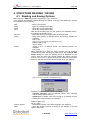
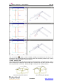
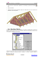
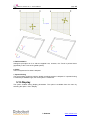
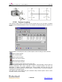
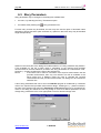
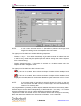
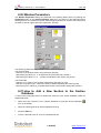
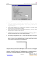
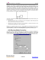
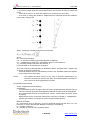
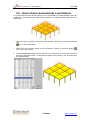
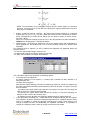
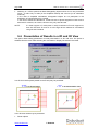
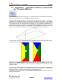
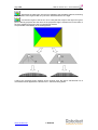
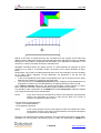
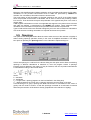
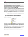
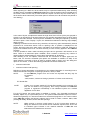
page: 39 CBS Pro Version 20.1 – User’s Manual YZ projection - projection onto YZ plane 3D projection - display of a structure in any position Model with rendering - display of a structure with object rendering switched on Skeleton model - objects are presented only by means of edges 3D view comprises 3 default structure projections: ZX, XY, YZ corresponding to the front view, top view and side view; the options are available in the menu View / 3D View / Projection, on the 3D View toolbar and in the context menu on the 3D layout / Projection (there are also keyboard shortcuts accessible: CTRL+ALT+1, CTRL+ALT+2, CTRL+ALT+3 as well as return to the initial projection CTRL+ALT+0) Parallel projection – switches on the axonometric structure view (the option is only available for 3D view) – a view in parallel projection (a view without perspective compression) Perspective projection - switches on the perspective structure view (the option is only available for 3D view); it is a structure view involving perspective compression; this compression is equivalent to the compression for wide-angle lenses in photo or video cameras (a perpective view enables ‘entering’ inside the object and recording a 3D movie presentation) Coordinate system – options for managing a position of the coordinate system Translate – translates the origin of the coordinate system by means of the mouse, the origin of the coordinate system is translated to the point indicated by the user on the screen (the mouse-click point) Rotate – rotates the coordinate system by means of the mouse; the rotation angle is calculated based on positions of two points defined with the mouse (the axis of the coordinate system is rotated in such a way so that the X’ axis creates with the X axis the angle defined by the user on the screen) NOTE: Calculation results for slabs, walls, raft foundations, that are available in the Properties dialog box, are presented in the current coordinate system (if the system is translated, the coordinates are translated as well, and if it is rotated, the slab is rotated in the graphical viewer). Global system – restores the initial (default) position of the coordinate system Define – option that enables defining a position of the coordinate system using the options provided in the Coordinate system dialog box; data determining translation or rotation of the coordinate system may be entered into appropriate edit fields located in the dialog box or defined graphically on the screen (to do so, the user should set the cursor in the edit field and enter data using the mouse) According to object – sets the coordinate system according to the local system of the selected object; an object should be selected with the mouse; position of the coordinate system depends on a mouse-click point - the system will be adopted on this object end that is positioned closer to the point selected with the mouse Previous / next story – options managing display of a story view When defining new elements (beam, column, etc.) it is possible to insert them at characteristic points (see options available in the Snap toolbar) indicated on elements from the previous / next story, analogously as for components from the current story; additionally, they may be snapped to intersections of objects from the current and previous / next story. Remarks on the options Previous / Next story: 1) after activating the option, the symbol appears next to the option’s name (these options cannot be activated simultaneously) 2) elements from these stories are shown in a different color (identical to the grid color) 3) these elements cannot be selected 4) elements are displayed together with descriptions (if descriptions are switched on). Characteristic points of elements from the previous and next stories are recognized by the program except when the Dimension Lines / Automatic option is active (according to © Robobat www.robobat.com