1
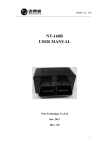
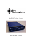
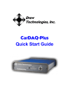
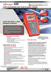
www.dgtech.com VSI-2534 User Manual Version 2.1 January 25, 2010 Foreword This document describes Dearborn Group’s (DG) VSI-2534, and SAE J2534 Pass-Thru device with its primary purpose to program automotive ECUs (Electronic Control Units). It provides module programming for development, end-of-line testing and re-programming. The VSI-2534 is also useful for vehicle diagnostics, development, general design, hardware-inthe-loop simulation and anywhere communications with a vehicle network are required. © 2006 - 2010 Dearborn Group, Inc. 33604 West Eight Mile Road Farmington Hills, MI 48335 Phone (848) 488-2000 • Fax (248) 888-9977 This document is copyrighted by the Dearborn Group, Inc. Permission is granted to copy any or all portions of this manual, provided such copies are for use with the product provided by the Dearborn Group, and that the name “Dearborn Group, Inc.” remains on all copies as on the original. 1 of 19 www.dgtech.com Table of Contents VSI-2534 User Manual ................................................................................................................. 1 Foreword ....................................................................................................................................... 1 1 Introduction ........................................................................................................................... 3 1.1 VSI-2534 hardware specifications ................................................................................. 4 1.2 Power connector ........................................................................................................... 4 1.3 Hardware overview........................................................................................................ 5 2 Software Setup...................................................................................................................... 7 3 Hardware Configuration ...................................................................................................... 12 3.1 First Time Hardware Connection to the PC................................................................. 12 3.2 Typical Hardware Connection to the PC ........................................................................... 14 3.3 Hardware Configuration Information ................................................................................. 15 3.4 Hardware Reflash of the VSI-2534 ................................................................................... 16 Appendix A – Pin Assignment for the OBD II Cable ................................................................... 19 2 of 19 www.dgtech.com 1 Introduction How it works: A PC is connected to a vehicle through the VSI-2534 “Pass-Thru device” to the OBD-II J1962 connector and on to the ECUs. The VSI-2534 provides the translation interface between the PC and the vehicle or module. The user application on the PC sends and receives data to the vehicle using J2534 function calls to this device. Provides support for: the most current version of the J2534 API (Version 04.04). Supports the following protocols: CAN (ISO 11898, J2284), Single-Wire CAN, ISO15765, ISO 9141, KWP2000, J1850 PWM (Ford SCP), J1850 VPWM (both GM Class 2 and Chrysler), SCI and GM-UART. Features: • USB 2.0 connection to a PC for fast downloads. (Operates at full network speed with fast and efficient data transfers.) • Connects to a vehicle with an OBDII cable or a custom cable. • Runs the SAE J1699 Vehicle Validation software. • On or off-board J2534 module programming. • Programming voltages – 5 to 20 V in 100 mV steps. • Useful for diagnostics or module development. 3 of 19 www.dgtech.com 1.1 VSI-2534 hardware specifications Dimensional Height: 4.375 in Width: 6.625 in. Depth: 1.312 in. Weight VSI-2534 tool: 13.3 oz. OBD II cable: 10.9 oz. Electrical Nominal Voltage: 12 VDC Maximum Voltage: 27 VDC Current consumption: Less than 200 mA at 12 VDC Temperature range: - 40 C to + 85 C 1.2 Power connector The VSI-2534 can be powered via the power jack (12 VDC adapter provided) or via the supplied OBD II cable attached to the vehicle. WARNING: The VSI-2534 SHOULD NOT be powered via the power jack AND the supplied OBD II cable SIMULTANEOUSLY. Connecting to multiple power sources may cause damage to the hardware. 1.2.1 Powering up the hardware Once a power source has been connected, the POWER LED should light. See Section 1.3.1 for details. 1.2.2 Vehicle network connection The vehicle network connection can be made by using the supplied OBD II cable or by a custom cable to the hardware’s DB-25 (female) connector. See Appendix A. 4 of 19 www.dgtech.com 1.3 Hardware overview The following figures show the external features of the VSI-2534: Figure 1: VSI-2534 Indicators 1.3.1 Status Indicators The VSI-2534 has three status LEDs that indicate activity of the following functions: PC Connection – Indicates that the VSI-2534 has established a connection to the PC, and if the link is “active.” Vehicle Connection – Indicates that the vehicle network connection is established / active. Power – Indicates that the VSI-2534 is connected to a power supply (either via the jack plug or through a vehicle connection), and whether or not the unit is operating properly. See details in the following table: 5 of 19 www.dgtech.com LED Name PC Connection Vehicle Connection Power LED State Description Off PC has not initialized communication with VSI-2534 via the USB data link. On (Solid Red) PC has initialized communication with VSI2534 via the USB data link. No bus activity. On (Alternating Red / Green) Activity on the PC-VSI-2534 connection via USB data link. Off No vehicle network protocol channel has been initialized for use. (Red) One or more vehicle network protocol channels have been initialized for use. No bus activity. On (Alternating Red / Green) There is activity on one or more vehicle network protocol channels. Off No power supplied to the VSI-2534 unit. On Unit is powered either via the vehicle connector or the external power jack. Unit is operating properly. On (Solid Green) Unit is powered either via the vehicle connector or the external power jack. Unit is not operating properly. On (Solid Red) Table 1: LED Descriptions 6 of 19 www.dgtech.com 2 Software Setup 1. Locate the “Setup_VSI2534.EXE,” click on it to start the Software Setup, and then click Next to proceed. 2. Click Next after exiting all Windows programs. 7 of 19 www.dgtech.com 3. Choose Destination Location for the installation. The default location is C:\Program Files\VSI-2534, and click Next to proceed. 4. Click Next to proceed. 8 of 19 www.dgtech.com 5. Make sure that you do not have the VSI-2534 hardware connected to the PC’s USB port. Click OK to proceed. 6. Installation is complete; click Finish. 9 of 19 www.dgtech.com 7. These are the files loaded into the location selected in Step #3. Applications and Manuals can be selected from Start | All Programs | VSI-2534. 8. These are the files loaded into the Reflash folder as seen in Step #8. 10 of 19 www.dgtech.com 9. These are the files loaded into the Sample folder as seen in Step #8. It contains the J2534SDK.exe, its source code, and Readme.txt. 10. These are the files loaded into the Source Code folder as seen in Step #9. 11 of 19 www.dgtech.com 3 Hardware Configuration 3.1 First Time Hardware Connection to the PC Step 1: Connect the VSI-2534 to a power source (Power adapter or powered from the OBD II cable). Note do not power unit from multiple sources. Power LED must be a solid Green. When the “Found New Hardware Wizard” screen appears, select: Yes now – and every time I connect a new device – then click on Next. 12 of 19 www.dgtech.com Step2: Click Next. Step3: Click Finish and the Hardware Ready to use prompt appears at the bottom right of the Windows screen. 13 of 19 www.dgtech.com 3.2 Typical Hardware Connection to the PC Step 1: Connect the VSI-2534 to a power source (Power adapter or powered from the OBD II cable). Note do not power unit from multiple sources. Power LED must be a solid Green. Step 2: Connect the VSI-2534’s USB cable to the PC that the software was installed on and not that the Power LED is a solid Green and the PC Connection LED is a solid RED. Step 3: Using an application such as the DG 2534 SDK a user can open a link to the hardware and connect with a protocol to a Vehicle or an Electronic Control Module (ECU). Note that when this occurs the Vehicle Connection LED is a solid RED. 14 of 19 www.dgtech.com 3.3 Hardware Configuration Information By running the VSI-2534 Utility.exe, a user can find out Hardware version, protocol support, and other information. Protocols Supported: J1850VPW, J1850PWM, CAN, ISO9141, ISO14230, ISO15765, SCI_A_ENGINE:1, SCI_A_TRANS:1, SCI_B_ENGINE:1, SCI_B_TRANS:1, SWCAN_ISO15765_PS, SWCAN_PS, GM_UART_PS J2534 API Version: 04.04 The Get Firmware button provides the Firmware version of the VSI-2534 hardware: Note: Do not have any other application running that uses the J2534 library. 15 of 19 www.dgtech.com The Turn Logging ON checkbox enables the Configuration button. The Configuration button enables the user to set Logging Type and Logging Method to create VSI-2534 DLL log: Note: Do not have any other application running that uses the J2534 library. 3.4 Hardware Reflash of the VSI-2534 To Reflash the VSI-2534 hardware go to C:\VSI-2534\Reflash (Or the user selected location during Software Setup) and run DPAFlash.exe. Step 1: Select the WriteFlash USB VSI 2534 from the Drop Down box, then click/select Setup. 16 of 19 www.dgtech.com Step 2: Select the correct *.S19 file. Step 3: Click OK. Step 4: Click/select Write Flash. 17 of 19 www.dgtech.com Step 5: Click/select Yes to proceed or No to cancel. If Yes, then a progress bar will appear. NOTE: If a problem occurs, the following dialog appears (please be sure to power cycle the unit prior to clicking O.K.). Step 6: Write Flash was successful, Power Cycle unit and then click/select OK. 18 of 19 www.dgtech.com Appendix A – Pin Assignment for the OBD II Cable VSI-2534 OBD II Cable Pin Assignment J1962 Connector 1 2 3 4 5 6 7 8 9 10 11 12 13 14 15 16 VSI-2534 Purpose/Function Single Wire CAN SAE J1850 (+) (not connected) Chassis Ground Signal Ground ISO 15765-4 / CAN High SCI_A_ENGINE (Rx) Programming Voltage ISO 9141 / ISO 14230 K-line SCI_A_ENGINE (Tx) SCI_A_TRANS (Tx) SCI_B_ENGINE (Tx) (not connected) GMUART SCI_B_TRANS (Rx) Programming Voltage SAE J1850 (-) Programming Voltage SCI_B_ENGINE (Rx) Programming Voltage Programming Voltage ISO 15765-4 / CAN Low Programming Voltage SCI_A_TRANS (Rx) ISO 9141 / ISO 14230 L-line Short to Ground SCI_B_TRANS (Tx) Unswitched Battery Voltage Not Used VSI-2534 DB 25 1 2 4 5 6 & 24 * 7 9 & 20 * 10 11 12 13 14 & 25 * 15 16 3, 8, 17 -19, 21 - 23 * NOTE: These pairs of pins are either connected together in the VSI 2534 tool or connected in the OBD II cable. Pins 6 and 24 are connected together within the VSI-2534 tool. Pins 9 and 20 are connected together within the OBD II cable. Pins 14 and 25 are connected together within the VSI 2534 tool. 19 of 19