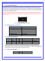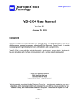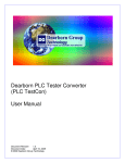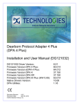
1
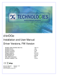
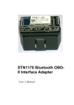
DG Technologies Netbridge Quad-CAN and LIN Interface Device NBRIDGEJ.DLL – SAE J2534 Compliant Drivers Installation and User Manual SAE J2534 Driver Version: Netbridge Firmware Version: Document Revision Revision 1.0.11 Document Date: March 3, 2015 © 2013-2015 Dearborn Group, Inc. 2.00 77.115 Netbridge Installation and User Manual Permission is granted to copy any or all portions of this manual, provided that such copies are for use with the Netbridge product and that “© 2013-2015 Dearborn Group, Inc.”, (herein referred to as “Dearborn Group”, “DG Technologies”, or “DG”), remains on all copies. The accompanying software, provided for use with the Netbridge, is also copyrighted. Permission is granted to copy this software for back-up purposes only. IMPORTANT To ensure your success with this product, it is essential that you read this document carefully before using the hardware. Damage caused by misuse of the hardware is not covered under product warranty. When using this manual, please remember the following: This manual may be changed, in whole or in part, without notice. DG assumes no responsibility for any damage resulting from the use of this hardware and software. Specifications presented herein are provided for illustration purposes only and may not accurately represent the latest revisions of hardware, software or cabling. No license is granted, by implication or otherwise, for any patents or other rights of DG or of any third party. Netbridge® and the DG® logo are registered trademarks of Dearborn Group, Inc. Other products that may be referenced in this manual are trademarks of their respective manufacturers. The Netbridge Product line and the products supporting the Netbridge have been awarded the following U.S. Patents: Patent # 6,772,248 7,152,133 7,337,245 7,725,630 8,032,668 8,152,557 7,984,225 7,660,934 Date 08-03-04 12-19-06 02-26-08 05-25-10 10-04-11 04-10-12 07-19-11 02-09-10 Patent Overview Protocol adapter for in-vehicle networks. Expanded functionality protocol adapter for in-vehicle networks. Passing diagnostic messages between a vehicle network and a computer. Passing diagnostic messages between a vehicle network and a computer using J1939 or J1708. Passing diagnostic messages between a vehicle network and a computer using J1939 or J1708. Positive locking mechanism for USB connected devices. ASCII gateway to in-vehicle networks. ASCII gateway to in-vehicle networks. DG Technologies 33604 West Eight Mile Road Farmington Hills, MI 48335 Phone (248) 888-2000 Fax (248) 888-9977 www.dgtech.com [email protected] [email protected] Page 2 of 18 © 2013-2015 Dearborn Group, Inc. Netbridge Installation and User Manual Table of Contents TABLE OF CONTENTS ......................................................................................................................................................... 3 1. SAFETY FIRST ............................................................................................................................................................... 4 2. INTRODUCING THE NETBRIDGE ................................................................................................................................. 5 2.1. 2.2. 2.3. 2.4. 2.5. 2.6. 3. NETBRIDGE PHYSICAL AND ELECTRICAL ................................................................................................................................................ 5 CAN CHANNEL INFORMATION........................................................................................................................................................... 5 LIN CHANNEL INFORMATION ............................................................................................................................................................ 5 OPERATING SYSTEMS SUPPORTED ...................................................................................................................................................... 6 NETBRIDGE PINOUTS ....................................................................................................................................................................... 6 SAE J2534 DEFINED PROTOCOLS SUPPORTED ..................................................................................................................................... 6 GETTING STARTED WITH THE NETBRIDGE .............................................................................................................. 7 3.1. 3.2. 3.1. 3.2. 3.3. 3.4. DRIVER INSTALLATION ...................................................................................................................................................................... 7 CONNECT USB CABLE TO THE NETBRIDGE AND THEN TO PC ................................................................................................................... 7 CONNECT NETWORK-SIDE CABLE TO THE NETBRIDGE............................................................................................................................. 7 CONNECT VEHICLE-SIDE CABLE TO THE VEHICLE .................................................................................................................................... 7 RUN THE WINDOWS FOUND NEW HARDWARE WIZARD ......................................................................................................................... 7 AUTOMATIC FIRMWARE UPDATE ....................................................................................................................................................... 7 4. SAE J2534 TROUBLESHOOTING WITH ADAPTER VALIDATION TOOL (OBDII) .................................................... 8 5. SAMPLE SOURCE CODE FOR SAE J2534 .................................................................................................................. 9 5.1. SAE J2534 SAMPLE SOURCE CODE.................................................................................................................................................... 9 DG UPDATE – PROGRAM OVERVIEW ...................................................................................................................... 10 6. 6.1. 6.2. 6.3. 6.4. 7. DG DRIVER UPDATE – INTERNET CONNECTION REQUIRED .................................................................................................................... 10 DG DRIVER UPDATE – INITIAL SCREEN ............................................................................................................................................. 10 DG DRIVER UPDATE – MAIN UPDATE SCREEN.................................................................................................................................... 11 ADVANCED SETTINGS – SETTING DEFAULT TIME FOR CHECK FOR UPDATES .............................................................................................. 13 TECHNICAL SUPPORT AND RETURN MERCHANDISE AUTHORIZATION (RMA) ................................................ 14 7.1. 7.2. 8. TECHNICAL SUPPORT ..................................................................................................................................................................... 14 RETURN MERCHANDISE AUTHORIZATION (RMA) ................................................................................................................................ 14 WARRANTY INFORMATION AND LIMITATION STATEMENTS ............................................................................... 15 8.1. 8.2. 9. WARRANTY INFORMATION ............................................................................................................................................................. 15 LIMITATION STATEMENTS ............................................................................................................................................................... 15 NETBRIDGE MANUAL FIRMWARE UPDATE ............................................................................................................ 16 9.1. 10. LAUNCH THE FIRMWARE UPDATER PROGRAM .................................................................................................................................... 16 SOFTWARE DEVELOPER/INTEGRATOR NOTES ................................................................................................. 17 10.1. 11. BUNDLING THE NETBRIDGE WITH YOUR OEM INSTALLATION – SILENT INSTALL..................................................................................... 17 NETBRIDGE TO NETBRIDGE “BACK TO BACK” CABLE .................................................................................... 18 Page 3 of 18 © 2013-2015 Dearborn Group, Inc. Netbridge Installation and User Manual 1. Safety First It is essential that the user read this document carefully before using the hardware. The Netbridge device is to be used by those trained in the troubleshooting and diagnostics of light-duty through heavyduty vehicles. The user is assumed to have a very good understanding of the electronic systems contained on the vehicles and the potential hazards related to working in a shop-floor environment. DG understands that there are numerous safety hazards that cannot be foreseen, so we recommend that the user read and follow all safety messages in this manual, on all of your shop equipment, from your vehicle manuals, as well as internal shop documents and operating procedures. Always block drive, steer, and trailer wheels both front and back when testing. Use extreme caution when working around electricity. When diagnosing any vehicle, there is the risk of electric shock both from battery-level voltage, vehicle voltages, and from building voltage. Do not smoke or allow sparks or open flames near any part of the vehicle fueling system or vehicle batteries. Always work in an adequately ventilated area, and route vehicle exhaust outdoors. Do not use this product in an environment where fuel, fuel vapor, exhaust fumes, or other potentially hazardous liquids, solids, or gas/vapors could collect and/or possibly ignite, such as in an unventilated area or other confined space, including below-ground areas. Page 4 of 18 © 2013-2015 Dearborn Group, Inc. Netbridge Installation and User Manual 2. Introducing the Netbridge The Netbridge product is used to connect CAN and LIN-based communication networks to a personal computer (PC) using a USB connection. This allows programs written for the PC to retrieve information as well as perform component level diagnostics, tests, databus analysis, and component reprogramming. The Netbridge comes standard with Society of Automotive Engineers (SAE) J2534-compliant drivers. Connecting to the LIN network is covered in the J2534 Extended Features document packaged with J2534. NOTE: As of January 2015, the Netbridge is only a SAE J2534-based device and no longer comes with Technology and Maintenance Council (TMC) Recommended Practice (RP) RP1210-compliant drivers. The RP1210 drivers are being maintained for customers who previously purchased a Netbridge and the drivers are being distributed to those customers manually. The Netbridge RP1210 drivers will no longer be on the DG website and no longer on DG Update. The DG Netbridge Quad-CAN and LIN Product 2.1. Netbridge Physical and Electrical Feature Dimensions Voltage Requirements Power Source Current Requirements Operating Temperature Range PC Communications Wired PC Connection Vehicle-Side Connector PC-Side Connector Data 6.1 x 2.5 x 1.2 inches 9 – 32 Volts DC External/Vehicle 250mA maximum through voltage range -40 to +85C USB Version 1.1 or Higher USB Cable (15 feet) DB25 Female Standard B-Type USB Jack 2.2. CAN Channel Information CAN Channel 1 2 3 4 5 Type HS CAN HS CAN HS CAN HS CAN SW CAN Pin Hi 13 24 17 9 Pin Lo 12 22 2 19 10 Supported Speeds 125k, 250k, 500k, 1000k 125k, 250k, 500k, 1000k 125k, 250k, 500k, 1000k 125k, 250k, 500k, 1000k 33.3k, 83.3k Termination Short Pins 3, 4 Short Pins 20, 21 None/External None/External Internal The HS CAN channels are in compliance with the ISO11898-2 specification. The SW CAN channel is in compliance with the SAE J2411 specification. The high speed CAN channel 1 and Single Wire CAN channel share hardware. You can only have one of these active at a time. Other than this limitation, the Netbridge supports all CAN channels being access simultaneously from the SAE J2534 drivers. 2.3. LIN Channel Information LIN Channel 1 Page 5 of 18 Pin 18 Supported Speeds Any rate up to 20k bps. © 2013-2015 Dearborn Group, Inc. Netbridge Installation and User Manual 2.4. Operating Systems Supported Windows Vista® 32-bit and 64-bit Versions Windows 7® 32-bit and 64-bit Versions Windows 8® 32-bit and 64-bit Versions 2.5. Netbridge Pinouts Signal Ground Power (9-32vdc) CAN1 Shield CAN1 Lo CAN1 Hi CAN1 Term 1 CAN1 Term 2 SW CAN CAN2 Term 1 CAN2 Term 2 CAN2 Shield CAN2 Lo CAN2 Hi CAN3 Lo CAN3 Hi CAN4 Lo CAN4 Hi CAN4 Shield LIN Netbridge 6 8 7 12 13 3 4 10 20 21 23 22 24 2 17 19 9 25 18 2.6. SAE J2534 Defined Protocols Supported CAN, CAN_PS CAN_CH1, CAN_CH2, CAN_CH3, CAN_CH4 ISO15765, ISO15765_PS, ISO15765_CH1, ISO15765_CH2, ISO15765_CH3, ISO15765_CH4 SW_CAN_PS, SW_ISO15765_PS J1939, J1939_CH1, J1939_CH2, J1939_CH3, J1939_CH4 Page 6 of 18 © 2013-2015 Dearborn Group, Inc. Netbridge Installation and User Manual 3. Getting Started with the Netbridge 3.1. Driver Installation Attention! Install Netbridge drivers from CD before connecting to your PC. To install drivers you must be logged into the administrator account or have administrator privileges. If you run into problems installing the drivers, please do not hesitate to contact technical support at (248) 888-2000. Insert the installation CD into your PC to begin the install. The latest drivers are always available at www.dgtech.com/download.php. If you have any questions, please contact our technical support staff. If setup does not begin automatically, browse to the CD and run the setup program: [CD_Drive_Letter]:\Setup_J2534Netbridge.exe 3.2. Connect USB Cable to the Netbridge and Then to PC Connect the USB cable to the Netbridge and PC. The USB cable that comes with the Netbridge has ears that allow the cable to be screwed into standoff screws on the frame, greatly reducing the chance of breaking the USB connector on the circuit board. 3.1. Connect Network-Side Cable to the Netbridge Connect the network-side cable to your Netbridge. Do not connect to the network-side first! Pins 6 and 8 on the DB25 connector are power and ground and can arc if not careful! This could damage the component you are connecting to. 3.2. Connect Vehicle-Side Cable to the Vehicle Now, connect the Netbridge to the network, verifying that the Netbridge Power LED is lit. 3.3. Run the Windows Found New Hardware Wizard In some versions of Windows the final step in driver installation (New Hardware Wizard) is automatic. In others, you will have to run the New Hardware Wizard to finalize the driver installation. After the New Hardware Wizard has finished running, you should be able to connect to the Netbridge device. 3.4. Automatic Firmware Update When a Netbridge drivers release is made, a specific version of firmware is validated with that release. In this release the firmware that was validated can be found on the cover page of this manual. After you have finished installing the Windows device drivers you can begin using your Netbridge. Every time you connect, the drivers check to see if a newer version of firmware is available on the hard drive. If a newer version is available the user will be prompted to upgrade to that version. Most applications can handle the delay; however there is a possibility that the user may have to restart their application. Page 7 of 18 © 2013-2015 Dearborn Group, Inc. Netbridge Installation and User Manual 4. SAE J2534 Troubleshooting with Adapter Validation Tool (OBDII) After you have installed the Netbridge drivers and connected the Netbridge to both the PC and network, make sure that the Netbridge Power LED is turned on. Run the Adapter Validation Tool (OBDII) to ensure that the PC is able to communicate with the Netbridge, and see data bus traffic on the network. Start Programs Dearborn Group Products Netbridge J2534 Adapter Validation Tool Select the correct Device: Device Netbridge – Dearborn Group, Inc. Protocol OBD II or Specific Protocol o Using the OBD II protocol selection means that AVT (OBDII) will attempt to connect using all OBD II protocols that the selected adapter supports. o You can also use a specific protocol (i.e. “ISO15765”), and AVT (OBDII) will connect using all speeds and options for that individual protocol. Then click the Run Test button. Depending on the results of the test, both the J2534 Status Window and J2534 Data Message Window will turn green (pass) or red (fail). 4.1.1. AVT (OBDII) Test Outcomes If the J2534 Status Window turns red, then there is a problem causing the PC not to communicate with the adapter. This may be something as simple as power to the adapter or a USB cabling issue. Disconnect the adapter from the network and PC; then reconnect them, this time connecting to another USB port on the PC. If the J2534 Status Window turns green and the J2534 Data Message Window turns red, then the PC is seeing the adapter, but not seeing messages from the network. Check the network to adapter cabling; disconnect the adapter from the network and PC; then reconnect them. If you see data in the J2534 Data Message Window, then the adapter is installed and functioning properly. Page 8 of 18 © 2013-2015 Dearborn Group, Inc. Netbridge Installation and User Manual 5. Sample Source Code for SAE J2534 DG had lots of inquiries about how to write software to the SAE J2534 API specification. DG responded by developing sample source code that demonstrates all necessary elements of databus communications: Load a SAE J2534 DLL and set function pointers to the functions in the DLL. Connect to a data bus. Set filters to allow messages to pass, or set ISO15765 flow control. Read, display, and log raw incoming messages. Write, display, and log raw outgoing messages. Decode data from these raw messages and display in English text. Close connection and unload DLL. 5.1. SAE J2534 Sample Source Code DG is the first in the industry to give away a complete set of SAE J2534 sample source code. This code is designed to monitor the most common OBDII databus, ISO15765 with 11-bit CAN identifiers. All code resides in one C++, VB.NET, or C# source file. Runs under a DOS command prompt (no GUI code). Easy to understand and well commented. Monitors the ISO15765 (11-bit standard CAN) data bus found in passenger cars from 2008 upward. Sets up all SAE J1979 flow control partnerships. Requests SAE J1979 Mode 1 supported PIDs. Displays Mode 1 Response message (PID=0x41) Demonstrates how to implement the send/receive messaging found in SAE J1979 (OBDII). The default installation path for the SAE J2534 sample source is: Page 9 of 18 C:\Dearborn Group Products\Netbridge J2534\SampleSource\ © 2013-2015 Dearborn Group, Inc. Netbridge Installation and User Manual 6. DG Update – Program Overview DG Update is an application that is installed with your Netbridge drivers. It will run (by default) once every 30 days, and will keep you up-to-date with the latest versions of drivers for all your DG products. With this application running regularly and Automatic Firmware Update turned on, this will keep your Netbridge up-to-date with drivers and firmware. DG recommends our customers keep up-to-date so that your applications run smoothly. The utility will run once every 30 days as a user logs on. This value is configurable, but defaults to 30 days. It can also be invoked manually from the Windows Start Menu: Start Programs Dearborn Group Products Netbridge J2534 DG Update 6.1. DG Driver Update – Internet Connection Required The DG Driver Update utility depends on successfully connecting to the Internet (to one of DG’s servers) to retrieve the latest version information and to download the latest drivers and applications if necessary. Many companies install firewalls and virus protection and these may block the DG server queries and responses. If you are connected to the Internet and have issues running DG Update (getting “Unable to connect to the internet to check for updates." messages), ensure that your firewall or virus protection will allow a connection to the following Internet host/site and port: fh.dtech.com, port 8888. There are too many firewall and virus programs on the market to cover in this manual, however if you contact your network administrator and provide them the host and port number, they should be able to configure your PC to allow the communication. You may also consult the Windows help system and/or the documentation for your firewall and/or virus protection software. 6.2. DG Driver Update – Initial Screen When the utility runs as a user logs on, the following screen will appear in the lower right hand corner of the screen. If you want to check for updates, ensure that your PC is connected to the Internet and click Continue. Clicking Cancel will cause DG Update to wait until the next time it is scheduled to run. Clicking Continue will bring up the main update screen. Page 10 of 18 © 2013-2015 Dearborn Group, Inc. Netbridge Installation and User Manual 6.3. DG Driver Update – Main Update Screen The main screen appears looking like this. Depending on which products are installed on your PC, the grid will display pertinent information about them. When selecting DG Update from the Windows Start Menu, this is the first screen to appear. Connect your PC to the Internet and click the Check For Updates button. Due to the nature of TCP/IP communications, errors connecting or sending/receiving of data are slow to appear, however the user will eventually be notified if there was a problem. If the check for updates was successful, the second column of the grid will display information returned from the DG server showing the most current versions and the Install Status row will change to red, green or blue. Color Green Red Blue Description Drivers up-to-date. No update necessary. Drivers are outdated. Update recommended. Drivers on your PC are newer than current version. This usually indicates you are running a beta copy of the Netbridge drivers. 6.3.1. Successful Connect – No Updates Available In this case, all drivers are current (green), and the Download button and progress bar do not display (see next paragraph). Clicking Exit will exit the program. Page 11 of 18 © 2013-2015 Dearborn Group, Inc. Netbridge Installation and User Manual 6.3.2. Successful Connect – Updates Available In this case, the DPA 5 drivers (the Netbridge would look similar) were out of date (red), and the Download button and progress bar show up on the screen. The progress bar will keep you informed of the download progress should you choose to download the latest drivers by clicking the Download button. When you click the Download button, you will be prompted to confirm starting of the download. The dialog box for the Netbridge would look similar. Note: The DG Update application can only download and install one item at a time. The user will be prompted for whichever one they want to update first. The reason that only one can be downloaded at a time is that the after the drivers are unzipped the installation program begins automatically. The DG Update program must exit because the installation program may have a newer version of the DG Driver Update utility to install. After choosing Yes, the program will download the drivers and update the progress bar while doing so. Once the drivers have been downloaded, the application will unzip them and start the installation process. The dialog box will go away after the install has been started. After the drivers have been downloaded (to the Windows temp directory – if you wish to save them for other machines), they will be unzipped and the program will exit right after starting the new driver installation. Follow the installation instructions in the appropriate User Manual. Page 12 of 18 © 2013-2015 Dearborn Group, Inc. Netbridge Installation and User Manual 6.4. Advanced Settings – Setting Default Time for Check for Updates If you want to turn off, or alter the timeout period where the user is prompted to check for updates (the dialog below), press the Advanced Settings button. The following dialog box will be displayed. To turn off the checking prompt, set the value to zero. Otherwise, you can set the number of days between checks. Page 13 of 18 © 2013-2015 Dearborn Group, Inc. Netbridge Installation and User Manual 7. Technical Support and Return Merchandise Authorization (RMA) 7.1. Technical Support After reading and following the troubleshooting and validation procedures and not being able to resolve an issue, please feel free to contact DG technical support. For users in the United States, technical support is available from 8:30 a.m. to 5:30 p.m. Eastern Time. You may also fax or e-mail your questions to us. For prompt assistance, please include your voice telephone number. Users not residing in the United States should contact your local DG representative. DG Technologies Technical Support Phone: Fax: E-mail: Web site: 7.2. (248) 888-2000 (248) 888-9977 [email protected] www.dgtech.com Return Merchandise Authorization (RMA) If technical support has deemed that there may be a physical problem with your Netbridge, you will be issued you an RMA number. You would then return the product along with any documentation of ownership you have (proof of purchase/price) to the following address: Product Service/Repairs Attn: RMA# xxxxxxx DG Technologies 33604 West 8 Mile Road Farmington Hills, MI 48335 Page 14 of 18 © 2013-2015 Dearborn Group, Inc. Netbridge Installation and User Manual 8. Warranty Information and Limitation Statements 8.1. Warranty Information The Dearborn Group, Inc. Netbridge is warranted against defects in materials and workmanship for two (2) years following date of shipment. Cables (both USB and vehicle) are warranted for 90 days. Dearborn Group, Inc. will, at its option, repair or replace, at no cost to the customer, products which prove to be defective during the warranty period, provided the defect or failure is not due to misuse, abuse, or alteration of the product. The customer is responsible for shipment of the defective product to DG. This warranty does not cover damage to any item that Dearborn Group, Inc. determines has been damaged by the customer's abuse, misuse, negligence, improper assembly, modification, or operation of the product. A Return Merchandise Authorization (RMA) number must be issued to the customer by our Technical Support Department at (248) 888-2000 and must be included with the product being returned (for more details, see section Return Merchandise Authorization (RMA)). A Netbridge is warranted for 90 days after a warranty repair, or to end of the original factory warranty period, whichever is longer. 8.2. Limitation Statements 8.2.1. General Limitation and Risk Assignment To the maximum extent permitted by applicable law, Dearborn Group, Inc. and its suppliers provide support services on an “as-is” basis and disclaim all other warranties and conditions not specifically stated herein, whether express, implied or statutory, including, but not limited to, any warranties of merchantability or fitness for a particular purpose, lack of viruses, accuracy or completeness of responses, results, lack of negligence or lack of workmanlike effort, and correspondence to description. The user assumes the entire risk arising out of the use or performance of the device, its operating system components, and any support services. 8.2.2. Exclusion of Incidental, Consequential and Certain Other Damages To the maximum extent permitted by applicable law, in no event shall Dearborn Group, Inc. or its suppliers be liable for any special, incidental, indirect or consequential damages whatsoever, including but not limited to: damages for loss of profit, loss of confidential or other information; business interruption; personal injury; loss of privacy, failure to meet any duty (including good faith or of reasonable care); negligence; and any other pecuniary or other loss related to the use of or the inability to use the device, components or support services or the provision of or failure to provide support services or otherwise in connection with any provision, even if Dearborn Group, Inc. or any supplier has been advised of the possibility of such damages. 8.2.3. Limitation of Liability and Remedies Notwithstanding any damages that you might incur for any reason whatsoever (including, without limitation, all damages referenced above and all direct or general damages), in no event shall the liability of Dearborn Group, Inc. and any of its suppliers exceed the price paid for the device. The user assumes the entire risk and liability from the use of this device. 8.2.4. Right to Revise or Update without Notice Dearborn Group, Inc. reserves the right to revise or update its products, software and/or any or all documentation without obligation to notify any individual or entity. 8.2.5. Governance The user agrees to be governed by the laws of the State of Michigan, USA, and consents to the jurisdiction of the state court of Michigan in all disputes arising out of or relating to the use of this device. 8.2.6. Contact Please direct all inquiries to: Dearborn Group, Inc. 33604 West 8 Mile Road Farmington Hills, MI 48335 Phone (248) 888-2000 Fax (248) 888-9977 Page 15 of 18 © 2013-2015 Dearborn Group, Inc. Netbridge Installation and User Manual 9. Netbridge Manual Firmware Update Even though automatic firmware update comes defaulted to on, there may be a time you need to update your Netbridge firmware manually. 9.1. Launch the Firmware Updater Program 1. Stop all applications that are using the Netbridge (if any). 2. Start the Netbridge Firmware Updater program: Start Programs Dearborn Group Products Netbridge J2534 Netbridge Firmware Updater 3. Select the correct firmware file (the latest version is already selected by default). If the firmware file exists, the Firmware box will turn green. a. NOTE: Firmware files are located in separate sub-directories under the Utilities directory where the Netbridge drivers are installed, typically: C:\Program Files\Dearborn Group Products\Netbridge J2534\Utilities\NetbridgeQC_Firmware\ 4. Click on the Update Firmware button and select Yes if you receive a warning dialog. 5. After the download is finished, disconnect power from the Netbridge, wait 5 seconds and then reconnect. Page 16 of 18 © 2013-2015 Dearborn Group, Inc. Netbridge Installation and User Manual 10. Software Developer/Integrator Notes This section is relevant only to software development engineers and systems integrators. 10.1. Bundling the Netbridge with Your OEM Installation – Silent Install DG has introduced a silent installation that software installation engineers can call that will install all Netbridge files that would normally be installed by running the installation interactively. The silent installation does not prompt the user or display a screen at any point. After the install, a reboot of the PC is necessary. 10.1.1. Silent Install Command Line Setup_NBRIDGE.exe /s /d_SILENT_ 10.1.2. Controlling Automatic Firmware Update Variable on Silent Install If you are a software development engineer or system integrator and wish to use the silent installation, but you want to change the Automatic Firmware Update setting to a value other than “1” (default), you can do so by changing the registry value of the following variable during a post-installation event. HKEY_LOCAL_MACHINE\SOFTWARE\ Dearborn Group Products\FirmwareUpdaterNetbridge\UpdateFirmware This variable is of the REG_SZ data type, however only the first character (‘0’,’1’,’2’,’3’) is used by the RP1210 Options program and the Netbridge drivers. Page 17 of 18 © 2013-2015 Dearborn Group, Inc. Netbridge Installation and User Manual 11. Netbridge to Netbridge “Back to Back” Cable This cable is for use with a second PC running a simulator or other software. Note that for CAN1 and CAN2, you can shunt pins together to enable internal termination resistors. For CAN3 and CAN4, you will need to add them outside of the Netbridge. Banana Jacks Ground (Pin 6) Ground (Pin 6) Power (Pin 8) J1708/J1587 Lo (Pin 14) J1708/J1587 Hi (Pin 15) CAN 1/J1939 Lo (Pin 12) Power (Pin 8) J1708/J1587 Lo (Pin 14) White CAN 1/J1939 Hi (Pin 13) J1708/J1587 Hi (Pin 15) CAN 1/J1939 Lo (Pin 12) CAN 1/J1939 Hi (Pin 13) CAN 1/J1939 Term Resistor (Pin 3) CAN 1/J1939 Term Resistor (Pin 3) CAN 1/J1939 Term Resistor (Pin 4) CAN 1/J1939 Term Resistor (Pin 4) SWCAN (Pin 10) SWCAN (Pin 10) GMUART/ALDL (Pin 16) GMUART/ALDL (Pin 16) GM J1850 VPW Hi (Pin 5) ISO9141 K-Line (Pin 1) GM J1850 VPW Hi (Pin 5) ISO9141 K-Line (Pin 1) ISO9141 L-Line (Pin 11) ISO9141 L-Line (Pin 11) CAN 2/J1939 Lo (Pin 22) Striped CAN 2/J1939 Lo (Pin 22) CAN 2/J1939 Hi (Pin 24) CAN 2/J1939 Term Resistor (Pin 20) Striped CAN 2/J1939 Hi (Pin 24) CAN 2/J1939 Term Resistor (Pin 20) CAN 2/J1939 Term Resistor (Pin 21) CAN 3/J1939 Lo (Pin 2) External CAN 3/J1939 Lo (Pin 2) CAN 3/J1939 Hi (Pin 17) Term Resistors CAN 3/J1939 Hi (Pin 17) CAN 4/J1939 Lo (Pin 19) External CAN 4/J1939 Lo (Pin 19) CAN 2/J1939 Term Resistor (Pin 21) CAN 4/J1939 Hi (Pin 9) DB25 Male Page 18 of 18 Term Resistors CAN 4/J1939 Hi (Pin 9) DB25 Male © 2013-2015 Dearborn Group, Inc.