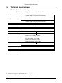
1
Kramer Electronics, Ltd.
USER MANUAL
Models:
TP-41, Component – S/PDIF Line Transmitter
TP-42, Component – S/PDIF Line Receiver
Contents
Contents
1
2
2.1
3
3.1
3.2
3.3
4
4.1
Introduction
Getting Started
Quick Start
Overview
About the TP-41 / TP-42
Shielded Twisted Pair (STP) / Unshielded Twisted Pair (UTP)
Recommendations for Achieving the Best Performance
Your Component – S/PDIF Line Transmitter and Line Receiver
Your TP-41 Component – S/PDIF Line Transmitter
1
1
2
3
3
4
4
5
5
4.1.1
4.1.2
Your TP-41 Component – S/PDIF Line Transmitter Topside
Your TP-41 Component – S/PDIF Line Transmitter Underside
5
6
4.2
Your TP-42 Component – S/PDIF Line Receiver
7
4.2.1
4.2.2
Your TP-42 Component – S/PDIF Line Receiver Topside
Your TP-42 Component – S/PDIF Line Receiver Underside
7
8
5
5.1
6
Connecting a Component – S/PDIF Distribution System
Wiring the CAT 5 LINE IN / LINE OUT RJ-45 Connectors
Technical Specifications
9
11
12
Figures
Figure 1: TP-41 Component – S/PDIF Line Transmitter
Figure 2: TP-41 Component – S/PDIF Line Transmitter (Top Side Panel)
Figure 3: TP-41 Component – S/PDIF Line Transmitter (Lower Side Panel)
Figure 4: TP-41 Component – S/PDIF Line Transmitter Underside
Figure 5: TP-42 Component – S/PDIF Line Receiver
Figure 6: TP-42 Component – S/PDIF Line Receiver (Top Side Panel)
Figure 7: TP-42 Component – S/PDIF Line Receiver (Lower Side Panel)
Figure 8: TP-42 Component – S/PDIF Line Receiver Underside
Figure 9: Component – S/PDIF Distribution System up to 300ft (100m) UTP Cable
Figure 10: CAT 5 PINOUT
5
5
6
6
7
7
7
8
10
11
Tables
Table 1: TP-41 Component – S/PDIF Line Transmitter Features
Table 2: TP-41 Component – S/PDIF Line Transmitter Underside Features
Table 3: TP-42 Component – S/PDIF Line Receiver Topside Features
Table 4: TP-42 Component – S/PDIF Line Receiver Underside Features
Table 5: CAT 5 PINOUT
Table 6: Technical Specifications of the TP-41 / TP-42
6
6
8
8
11
12
i
Introduction
1
Introduction
Welcome to Kramer Electronics! Since 1981, Kramer Electronics has been
providing a world of unique, creative, and affordable solutions to the vast
range of problems that confront the video, audio, presentation, and
broadcasting professional on a daily basis. In recent years, we have
redesigned and upgraded most of our line, making the best even better! Our
1,000-plus different models now appear in 11 groups1 that are clearly
defined by function.
Thank you for purchasing your Kramer TOOLS TP-41 Component –
S/PDIF Line Transmitter and Kramer TOOLS TP-42 Component – S/PDIF
Line Receiver, which are ideal for high-quality home cinema.
The TP-41 and TP-42 can use existing UTP cabling that results in an efficient,
fast and uncluttered environment for:
Studios, airports, offices and hospitals
Security and military applications
The package includes the following items:
TP-41 and/or TP-42
Power supply2, and this user manual3
2
Getting Started
We recommend that you:
Unpack the equipment carefully and save the original box and
packaging materials for possible future shipment
Review the contents of this user manual
Use Kramer high-performance high-resolution cables4
1 GROUP 1: Distribution Amplifiers; GROUP 2: Switchers and Matrix Switchers; GROUP 3: Control Systems; GROUP 4:
Format/Standards Converters; GROUP 5: Range Extenders and Repeaters; GROUP 6: Specialty AV Products; GROUP 7:
Scan Converters and Scalers; GROUP 8: Cables and Connectors; GROUP 9: Room Connectivity; GROUP 10: Accessories
and Rack Adapters; GROUP 11: Sierra Products
2 A separate power supply is included with each product. As an option, you can purchase the Kramer VA-50P 6-Port
Universal 12-Volt Power Supply, that supplies power to up to 6 Kramer devices that require 12V DC
3 Download up-to-date Kramer user manuals from the Internet at this URL: http://www.kramerelectronics.com
4 The complete list of Kramer cables is on our Web site at http://www.kramerelectronics.com
1
Getting Started
2.1
Quick Start
This quick start chart summarizes the basic setup and operation steps.
2
KRAMER: SIMPLE CREATIVE TECHNOLOGY
Overview
3
Overview
This section describes:
A summary of the TP-41, TP-42, see section 3.1
Using shielded twisted pair (STP) / unshielded twisted pair (UTP),
see section 3.2
Recommendations for achieving the best performance, see section
3.3
3.1
About the TP-41 / TP-42
Using the TP-41 Component – S/PDIF Line Transmitter with the TP-42
Component – S/PDIF Line Receiver constitutes a Component – S/PDIF Line
transmitter / receiver system. The TP-42 receives the CAT 5 signal,
decodes it and simultaneously distributes it to the YUV output.
The TP-41 Component – S/PDIF Line Transmitter includes:
A YUV1 input on three RCA connectors
A digital audio input (S/PDIF) on an RCA connector
A CAT 5 output for signal transmission to the TP-42
Individual level controls for the Y, U, and V signals
Audio level control
The TP-42 Component – S/PDIF Line Receiver includes:
A YUV1 output on three RCA connectors
A digital audio output (S/PDIF) on an RCA connector
A CAT 5 input for signal reception from the TP-41
Individual level and EQ. controls for the Y, U, and V signals
Audio level and EQ. controls
Kramer twisted pair adapters are an excellent way to solve remote
monitoring requirements without using more costly coaxial cable or fiber,
or wireless transmission systems.
1 Also known as Y, B-Y, R-Y, or Y, Pb, Pr
3
Overview
3.2
Shielded Twisted Pair (STP) / Unshielded Twisted Pair (UTP)
We recommend that you use shielded twisted pair (STP) cable. There are
different levels of STP cable available, and we advise you to use the best
quality STP cable that you can afford. Our STP skew-free cable, Kramer
BC-SXTP, is intended for transmitting VGA signals. Our non-skew-free
cable, Kramer BC-STP, is intended for digital signals.
The compliance to electromagnetic interference was tested using STP
cables, therefore we recommend using those cables.
Although unshielded twisted pair (UTP) cable might be preferred for long
range applications, the UTP cable should be installed far away from electric
cables, motors and so on, which are prone to create electrical interference.
However, since the use of UTP cable might cause inconformity to
electromagnetic standards, Kramer does not commit to meeting the standard
with UTP cable.
3.3
Recommendations for Achieving the Best Performance
Achieving the best performance means:
Use only good quality connection cables1 to avoid interference,
deterioration in signal quality due to poor matching, and elevated
noise levels (often associated with low quality cables)
Avoid interference from neighboring electrical appliances that
may adversely influence signal quality and position your Kramer
TP-41, TP-42 away from moisture, excessive sunlight and dust
Caution – No operator-serviceable parts inside unit.
Warning – Use only the Kramer Electronics input power
wall adapter that is provided with this unit2.
Warning – Disconnect power and unplug unit from wall
before installing or removing device or servicing unit.
1 Available from Kramer Electronics on our Web site at http://www.kramerelectronics.com
2 For example, part number 2535-052001
4
KRAMER: SIMPLE CREATIVE TECHNOLOGY
Your Component – S/PDIF Line Transmitter and Line Receiver
4
Your Component – S/PDIF Line Transmitter and Line
Receiver
This section describes the:
TP-41 Component – S/PDIF Line Transmitter, see section 4.1
TP-42 Component – S/PDIF Line Receiver, see section 4.2
4.1
Your TP-41 Component – S/PDIF Line Transmitter
For a description of the TP-41:
Topside, see section 4.1.1
Underside, see section 4.1.2
4.1.1 Your TP-41 Component – S/PDIF Line Transmitter Topside
Figure 1, Figure 2, Figure 3 and Table 1 define the TP-41:
Figure 1: TP-41 Component – S/PDIF Line Transmitter
Figure 2: TP-41 Component – S/PDIF Line Transmitter (Top Side Panel)
5
Your Component – S/PDIF Line Transmitter and Line Receiver
Figure 3: TP-41 Component – S/PDIF Line Transmitter (Lower Side Panel)
Table 1: TP-41 Component – S/PDIF Line Transmitter Features
Feature
12V DC
LINE OUT RJ-45 Connector
S/PDIF RCA Connector
V RCA Connector
U RCA Connector
Y RCA Connector
ON LED
INPUTS
#
1
2
3
4
5
6
7
Function
+12V DC connector for powering the unit
1
Connects to the LINE IN connector on the TP-42
Connects to the digital audio source
Connects to the component video source
Illuminates when receiving power
4.1.2 Your TP-41 Component – S/PDIF Line Transmitter Underside
Figure 4 and Table 2 define the underside of the TP-41:
Figure 4: TP-41 Component – S/PDIF Line Transmitter Underside
Table 2: TP-41 Component – S/PDIF Line Transmitter Underside Features
#
1
2
3
4
Feature
V LEVEL Trimmer
U LEVEL Trimmer
Y LEVEL Trimmer
AUDIO LEVEL Trimmer
Function
Adjusts2 the V output signal level
Adjusts2 the U output signal level
Adjusts2 the Y output signal level
Adjusts2 the volume
1 Using a straight pin to pin UTP cable with RJ-45 connectors at both ends (the PINOUT is defined in Table 5 and Figure 10)
2 Insert a screwdriver into the small hole and carefully rotate it, trimming the level
6
KRAMER: SIMPLE CREATIVE TECHNOLOGY
Your Component – S/PDIF Line Transmitter and Line Receiver
4.2
Your TP-42 Component – S/PDIF Line Receiver
For a description of the TP-42:
Topside, see section 4.2.1
Underside, see section 4.2.2
4.2.1 Your TP-42 Component – S/PDIF Line Receiver Topside
Figure 5, Figure 6, Figure 7 and Table 3 define the TP-42:
Figure 5: TP-42 Component – S/PDIF Line Receiver
Figure 6: TP-42 Component – S/PDIF Line Receiver (Top Side Panel)
Figure 7: TP-42 Component – S/PDIF Line Receiver (Lower Side Panel)
7
Your Component – S/PDIF Line Transmitter and Line Receiver
Table 3: TP-42 Component – S/PDIF Line Receiver Topside Features
Feature
12V DC
LINE IN RJ-45 Connector
S/PDIF RCA Connector
V RCA Connector
U RCA Connector
Y RCA Connector
ON LED
OUTPUTS
#
1
2
3
4
5
6
7
Function
+12V DC connector for powering the unit
1
Connects to the LINE OUT connector on the TP-41
Connects to the digital audio acceptor
Connects to the component video acceptor
Illuminates when receiving power
4.2.2 Your TP-42 Component – S/PDIF Line Receiver Underside
Figure 8 and Table 4 define the underside of the TP-42:
Figure 8: TP-42 Component – S/PDIF Line Receiver Underside
Table 4: TP-42 Component – S/PDIF Line Receiver Underside Features
#
1
2
3
4
5
6
7
8
Feature
Y EQ. Trimmer
Y LEVEL Trimmer
U EQ. Trimmer
U LEVEL Trimmer
V EQ. Trimmer
V LEVEL Trimmer
AUDIO EQ. Trimmer
AUDIO LEVEL Trimmer
Function
Adjusts2 the cable compensation equalization level for output Y
Adjusts2 the Y output signal level
Adjusts2 the cable compensation equalization level for output U
Adjusts2 the U output signal level
Adjusts2 the cable compensation equalization level for output V
Adjusts2 the V output signal level
Adjusts2 the audio equalization level
Adjusts2 the volume
1 Using a straight pin to pin UTP cable with RJ-45 connectors at both ends (the PINOUT is defined in Table 5 and Figure 10)
2 Insert a screwdriver into the small hole and carefully rotate it, trimming the level
8
KRAMER: SIMPLE CREATIVE TECHNOLOGY
Connecting a Component – S/PDIF Distribution System
5
Connecting a Component – S/PDIF Distribution System
To configure a TP-41 / TP-42 Component – S/PDIF distribution system
(for example, for high quality home cinema), as Figure 9 illustrates, do the
following:
1. On the TP-41, connect a component video source (for example, a DVD
player) to the:
Y, U, and V RCA (component video) INPUT connectors
S/PDIF (digital audio) RCA INPUT connector
2. On the TP-42, connect the:
Y, U, and V RCA (component video) OUTPUT connectors to
a component acceptor (for example, a plasma monitor)
S/PDIF (digital audio) RCA OUTPUT connector to an
AV-Receiver
3. Connect the LINE OUT connector of the TP-41 to the LINE IN connector
of the TP-42, via UTP cabling (maximum range of up to 300ft (100m)).
4. On each TP-41 / TP-42 unit:
Connect a 12V DC power adapter to the power socket and
connect the adapter to the mains electricity1
If necessary, adjust2 the appropriate level(s), by inserting a
screwdriver into the small hole and carefully rotating it
1 Note, the TP-41, TP-42 does not have the power connect feature
2 On the TP-41, adjust the audio level and/or the Y, U, and V levels. On the TP-42, adjust the audio level, the audio EQ., the
Y, U, and V levels, and/or the Y, U, and V EQ.
9
Connecting a Component – S/PDIF Distribution System
Figure 9: Component – S/PDIF Distribution System up to 300ft (100m) UTP Cable
10
KRAMER: SIMPLE CREATIVE TECHNOLOGY
Connecting a Component – S/PDIF Distribution System
5.1
Wiring the CAT 5 LINE IN / LINE OUT RJ-45 Connectors
Table 5 and Figure 10 define the CAT 5 PINOUT, using a straight pin to pin
cable with RJ-45 connectors:
Table 5: CAT 5 PINOUT
EIA /TIA 568A
PIN
1
2
3
4
5
6
7
8
Wire Color
Green / White
Green
Orange / White
Blue
Blue / White
Orange
Brown / White
Brown
Figure 10: CAT 5 PINOUT
EIA /TIA 568B
PIN
1
2
3
4
5
6
7
8
Wire Color
Orange / White
Orange
Green / White
Blue
Blue / White
Green
Brown / White
Brown
Pair 1
4 and 5
Pair 1
Pair 2
3 and 6
Pair 2
4 and 5
1 and 2
Pair 3
1 and 2
Pair 3
3 and 6
Pair 4
7 and 8
Pair 4
7 and 8
11
Technical Specifications
6
Technical Specifications
Table 6 defines the technical specifications:
1
Table 6: Technical Specifications of the TP-41 / TP-42
INPUTS:
TP-41:
TP-42:
1 RJ-45 CAT 5 shielded connector (Line In)
OUTPUTS:
TP-41:
1 RJ-45 CAT 5 shielded connector (Line Out)
1 set of component video (Y, U, V) on RCA connectors
1 S/PDIF (digital audio) on an RCA connector
TP-42:
1 set of component video (Y, U, V) on RCA connectors
1 S/PDIF (digital audio) on an RCA connector
MAX. OUTPUT LEVEL:
VIDEO: 2.1Vpp
AUDIO: 2.1Vpp (S/PDIF)
VIDEO RESOLUTION:
Up to 1080i
2
BANDWIDTH (-3dB):
AUDIO: 53.4MHz
DIFF. GAIN:
0.15%
DIFF. PHASE:
0.68 Deg
K-FACTOR:
0.8%
S/N RATIO:
VIDEO: 78.1dB
AUDIO: 78.4dB
CROSSTALK (all hostile): VIDEO: –55.5dB
AUDIO: –50.5dB
TP-41: YUV Level: –1.7dB to +0.7dB
CONTROLS:
S/PDIF Level: –1.9dB to +0.4dB
TP-42:
COUPLING:
POWER SOURCE:
YUV Level: –0.7dB to +0.8dB
YUV Equalization: 0 to +7.5dB
S/PDIF Level: –0.5dB to +1.2dB
S/PDIF Equalization: 0 to +7.8dB
VIDEO: DC
AUDIO: DC
TP-41: 12V DC, 95mA
DIMENSIONS:
WEIGHT:
ACCESSORIES:
TP-42: 12V DC, 82mA
TP-41 / TP-42: 12cm x 7.5cm x 2.5cm (4.7" x 2.95" 0.98", W, D, H)
TP-41 / TP-42: 0.3kg (0.67lbs) approx.
Power Supply
1 Specifications are subject to change without notice
2 Specifications for 100m of CAT5 UTP cable, unless otherwise specified
12
KRAMER: SIMPLE CREATIVE TECHNOLOGY
13
For the latest information on our products and a list of Kramer
distributors, visit our Web site: www.kramerelectronics.com,
where updates to this user manual may be found.
We welcome your questions, comments and feedback.
Safety Warning:
Disconnect the unit from the power supply before
opening/servicing.
Caution
Kramer Electronics, Ltd.
Web site: www.kramerelectronics.com
E-mail: [email protected]
P/N: 2900-000041 REV 5