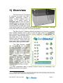
1
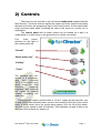
by ADL PRODUCTS
User Manual and
Technical Specifications
Version 1.11 issued
for beta testing
9th October 2008
All rights reserved by ADL Products, © 2008. The term
RainDirector is proprietary and protected by trade mark
legislation. UK, European and Worldwide patents for the
RainDirector and certain features applied for. No part of this
document can be reproduced without our permission
R.Lester, A.Lester, M.Bicknell
[email protected]
Rain Director® Specs Oct 2008
-
phone 01733 405100
Page 1
1) Overview
The Rain Director® is designed
to optimise the water flow from a
rainwater harvesting system to
toilets, washing machine and the
garden in a typical house. Its
intelligent tank (in the roof space),
control panel (at ground level) and
electric pump (submerged in the rain
harvesting tank) provide water supply
under gravity wherever it’s needed while reducing power consumption, reducing
pump wear and ensuring crystal clear water at all times.
The Rain Director® enables sufficient rainwater to be stored in a header
tank (cutaway diagram, above right) to meet the daily needs of a household’s
toilet cisterns and washing machines, without continually running pumps. The
Rain Director® allows all the water in
the header tank to be used before
refilling, which therefore avoids the
cost of electricity1, pump strain and
pump wear due to pumping water
every time a small amount is used.
The Rain Director® allows
the household to use as much
rainwater as needed and reduces
the amount of mains water used to a
minimum. It also makes mains water
available in the event of a long
drought and an empty rain water
tank.
While
normal
function
requires no user input, the control
panel (picture, right) provides
certain functions at the push of a
button, needed from time to time.
Backup systems ensure fail safe
operation and continuity of supply.
The comparative table in section 9 below shows the advantages over
existing solutions on the market.
1
Note that an electric pump uses a disproportionately high amount of electric power (a “surge”) every time it
starts up. The Rain Director’s pump starts up about 10 times less often than those in other systems which have to start
every time a toilet is flushed or when pressure in the pipe subsides.
Rain Director® Specs Oct 2008
Page 2
2) Controls
There are no user controls in the roof-space header tank supplied with the
Rain Director. Two float sensors register the upper and lower water levels within
the tank and inform the programme logic in the control panel. A float switch (ball
cock) prevents mains water overfilling the tank in the event of a power cut or
malfunction.
The control panel with its water valves can be located on a wall in a
visible place in a utility room on the ground floor or where convenient.
Four
“push
button”
switches on the right of
the control panel are;
“Normal”
“Mains water only”
“Holiday”
“Flush”
The switches are connected to a programmable
logic
controller
(PLC) in the control box,
which stores the Rain
Director’s
computer
programs and converts
the inputs to useable
outputs controlling the
water flow.
Three physical outputs, powered from a 12v A.C. supply by the controller, turn
on and off the three solenoid water valves in the housing to the left of the control
panel. A fourth water valve, the mains water bypass, is to the left of the others,
and can only be turned on and off manually. This maintains a supply if there is no
rainwater left and there is a power cut.
Rain Director® Specs Oct 2008
Page 3
3) Operation & indicator lights
2 level sensors in the header tank provide data to the computer built in to
the control panel which then controls 3 electrically operated water valves
alongside:
• The rainwater solenoid valve controls the inflow of pumped water from a 240
volt pressure-sensitive demand pump in the underground rain water storage
tank. When the valve opens, the pump registers the drop in pressure and
supplies water to the header tank until a “tank full” signal closes the valve.
• The mains solenoid valve is connected to the mains water supply. This is
used mainly as a back up water supply if the rainwater should run out.
• The flush valve can be opened by the system to let water out at any time.
• In the event of a power supply failure a mains bypass can be opened
manually and the tank will fill with mains water until the conventional ball cock
closes (3.9 below).
The LED lights on the left of the control panel indicate the status of the system:
Rain filling
A demand has been made on water supply from the
header tank so rain water is flowing normally into the
header tank.
Mains filling
Mains water is flowing into the header tank, either
because the rain water tank is empty or the user has
directed it to do so
Mains water only
“Mains water only” button has been pressed, typically
to save rain water. Press “Normal” to revert to normal
operation.
Holiday mode
Flush mode
Mains water not
working (red)
Power On
Rain Director® Specs Oct 2008
The “Holiday” button has been pressed. The header
tank has emptied its rain water and filled up with
mains water. This is to avoid the rainwater getting
brackish in the header tank. You may flush toilets with
mains water before leaving the house.
Existing water in the header has been discarded and
new rain water is flowing into the header – either
because user has pressed “Flush” or because “Auto
Tank Refresh” mode has been triggered by timer and
conditions.
Rain Director has also detected that the mains water
is not flowing; this could be due to the home’s mains
stopcock being turned off, major leak or some other
mains water failure. Investigate cause immediately.
Rain Director has been turned on and is under main
electric power. Stays on during normal use. Flashes
during “Set Up” mode.
Page 4
3.1
Normal Running
During normal use the Rain Director® control system monitors and
maintains the availability of rainwater in the tank.
The Power On indicator light is on.
The Rain filling light flashes when rain water is being pumped into
the header tank.
Should the rainwater run out or become otherwise
unavailable, the system automatically switches to mains water and
the Mains filling light begins flashing.
In exceptional circumstances, the Rain Directors’ mode is changed
automatically using the control panel buttons, as follows.
3.2
Set-up Mode
(lasts several hours)
Flashing
The set-up (or “commissioning” mode) is used once
after installing when the user or installing engineer press both the flush and
holiday buttons at the same time. This process automatically calibrates the flow
timers and stores in memory the time it takes for the rain water to fill the tank and
for the mains water to fill the tank. At any time thereafter, if the top sensor fails,
the tank fills with rain water (if available) or mains water according to the time
intervals memorised.
The reason why the time intervals have to be calibrated for each Rain
Director® installation is because different sized header tanks, different water
pressures and other variables make it impossible to establish the fill times as a
factory setting. Calibration of the flow timers by set-up mode only needs to be
completed once in the system’s lifetime unless a new header tank or pump is
fitted.
During the set-up process the Power On light flashes. The tank fills with
rainwater, flushes, fills with mains water and flushes… then repeats the process
two more times. The computer takes the average of the fill time for rainwater and
for mains water and stores these two values. During these cycles, you will see
the Rain Filling, Mains filling and Flush indicator lights come on and off. The
set-up may therefore take several hours. You can interrupt the process if
absolutely necessary but you would have to run it again to complete the
installation.
3.3
Auto Tank Refresh
If the water in the header tank is not used in a 3-day period, the
refresh program automatically flushes out the system, emptying the
header tank back into the underground tank. The header then refills with fresh
rainwater. This feature is disabled when the holiday mode is running. If the
house is left empty, and the holiday button is not pressed, the Rain Director®
automatically refreshes the system every 3 days. The purpose of refresh is to
prevent rainwater in the header tank (which in a roof space in summer could be
Rain Director® Specs Oct 2008
Page 5
at 20°C or higher) from getting brackish; cool clear water from the underground
tank (at about 5°C or less) is pumped into the header.
3.4
Flush Mode
The flush mode allows the rainwater in the header tank to be
changed by pressing the flush button on the panel. When the valve is
opened the water will flush out and is directed back into the rainwater-harvesting
tank. This might be triggered if little water has been used and the ambient
temperature is high; this gives the user the choice to avoid brackishness by
replacing the water in the header tank. This is the same as Auto Tank Refresh
but triggered manually.
3.5
Holiday Mode
The holiday mode empties the header tank and then refills with
mains water. Remember to press the holiday button a few hours in
advance of leaving. Providing the header tank has had time to fill with mains
water and providing you flush the toilets twice after pressing the holiday button,
the toilet cisterns and bowls are filled with chlorinated water that stays fresh for
however long the duration of the holiday. On return from holiday all toilets and
washing machines will be available as normal and the Rain Director® system will
then automatically revert to normal mode.
3.6
Mains Water Only Mode
Once the mains water only button is pressed, the system
selects mains water to fill the header tank. The existing water in the
header tank is used as usual but is replenished with mains water. This method of
operation continues until the normal button is selected. This mains water only
feature is provided to enable the rain water to be conserved for garden use
during a drought. The same pump submerged in the rain storage tank can still be
used at that time provided that its output is equipped with a T joint feeding a tap
or other garden outlet. Alternatively a second pump for garden use only can be
out in the rain storage tank.
3.7
In the event of power cut
3.8
Time Limit Flow Mode – upper sensor failure
In the event of a mains electricity power cut, firstly, water in Off
the header tank flows by gravity as required until it runs out. Secondly, thereafter,
the mains water supply valve can be manually opened and the tank will fill with
mains water until the conventional ball cock closes; see instructions in Manual
mains water bypass in 3.9 below. This valve will require closing after the power
is restored.
In the unlikely event of a failure of the UPPER float sensor in
the header tank the Rain Director® tries to fill the header tank,
establishes that the upper sensor has not given a “full” signal, and “times out”.
The Main water not working light illuminates. Rain Director® then switches to its
back up program which fills the tank according to the flow time stored in memory.
Please also read the note on Set-Up mode in 3.2 above. The warning light
Rain Director® Specs Oct 2008
Page 6
indicates that the sensor most likely needs changing (unless both rain and mains
water had run out).
3.9
Manual mains water bypass – lower sensor failure
In the unlikely event of a failure of the LOWER float sensor in the header
tank, Rain Director® will not know that the tank is empty. Water will be not
available neither at toilets, washing machine or other appliances feed with
rainwater. No indicator light shows.
To reinstate water supply,
remove the cover surrounding the
control panel and water valves.
Select the manual (non electric)
valve to the far left (blue in the
picture, right, of the control panel
without its cover) and turn it 90
degrees to open the mains flow.
1
Electric power to the other valves
is 12 volt only so there is no risk of
2
electric shock. Mains water flows
3
into the header tank until the ball
cock valve turns the flow off. This
safety feature works even if there
is no electric power to the system.
Call your installer or supplier to confirm the fault and replace the part.
3.10 Overflow tower – multiple failures
The overflow tower in the header tank is a large, open-topped, watertight
cylinder whose top is below the top of the tank. If all other systems were to fail,
and rain or mains water is flowing unchecked into the header tank, the excess
water flows over the top of the cylinder and out of the 40mm overflow pipe. The
large diameter overflow tower provides the head and the impulsion to ensure high
volume flow through the overflow pipe, thus reducing to a minimum the risk of
any overflow over the top edges of the tank itself into the roof space.
3.11 Garden Use and optional smaller pump types
The Rain Director is optimised for supply of rainwater to toilets and
washing machine in the house, but the stored rainwater can of course also be
used for watering the garden, washing the car and other outdoor uses. For this
reason The Rain Director is supplied with a 1100 watt pressure-sensitive pump;
it’s perfect for long term domestic use but can also supply rainwater to a hose as
required. The outlet to the garden can be plumbed at any point in the pipe
between the pump and the header tank, so it will get the full power of the pump. If
it’s plumbed after the header tank then that outlet will only get gravity feed.
If your system is not going to supply an outdoor tap, then a smaller pump,
using less electrical power, can be fitted with The Rain Director. Enquire at
RainWaterHarvesting.co.uk or your supplier for suitable types.
Rain Director® Specs Oct 2008
Page 7
4.
The header tank
The rain water supply
pipe (A) is routed to the bottom
of the tank, in order to reduce
turbulence or splash.
The mains supply (B) is
at a lower pressure and, to
provide the air gap required by
U.K. building regulations, it
flows into the tank from above
the surface of the water. Mains
flow is solenoid controlled. The
ball cock valve (C) prevents
overflow of the mains water
flow even when there is no power.
B
A
C
Cutaway view of
smart header tank
E
D
D
G
F
The supply of water to the tank is governed by two level sensors at the top
and bottom of the tank (D).
The overflow tower (E)
is a large, open-topped,
watertight cylinder whose top
is below the top of the tank. If
all other systems were to fail,
water flows over the top of
the cylinder and out of the
40mm overflow pipe (F). The
large
diameter
overflow
tower provides the head and
the impulsion to ensure high
volume flow through the
overflow pipe, thus reducing
to a minimum the risk of any
overflow over the top edges
of the tank itself into the roof
space.
B
C
D
E
A
Side view of components
of the smart header tank
D
F
G
The feed pipe (G) takes water from the tank to be used around the house.
It is suitable for compression-fit 22mm copper or plastic variant piping.
The following 5 diagrams show the smart header tank in cutaway view in
different phases of function.
Rain Director® Specs Oct 2008
Page 8
4.1
Tank is empty
Lower sensor is down. Rain Director®
knows tank is empty. Control box orders tank to
fill with rainwater if available.
4.2
Rain filling
Control box has sensed there is rainwater
available and has ordered tank to fill with
rainwater.
4.3
Rain full
Upper sensor has been raised by water.
Control box sensed there was rainwater available
and has filled with rainwater.
4.4
Mains filling
Control box has sensed there is no more
rainwater and has ordered tank to fill with mains
water.
4.5
Mains full
Float valve has been raised by water.
Control box knows tank is full and has turned off
mains water input.
Rain Director® Specs Oct 2008
Page 9
5) Installation
These instructions assume that a
rainwater harvesting tank has been
installed on the premises. See also page
13 for a schematic diagram.
1
2
3
5.1 Pump
5.1.1 Lower the rainwater pump into the
rainwater storage tank with a cord
and secure the top of the cord to the turret of the tank to enable the pump
to be pulled out again for maintenance.
5.1.2 Connect the pump’s cable to a permanent 240 volt AC supply which
should be turned on at the time the control panel is switched on.
5.1.3 Connect the optional floating intake to the input of the pump
5.1.4 Connect the rainwater supply from the output of the pump in the
underground storage tank to the bottom of the middle valve (2 above), and
the top of the valve to the header tank at (A).
5.2 Header Tank
5.2.1 Install the header tank in the roof space with anti-freeze lagging as with
any tank.
5.3 Control Panel
5.3.1 Mount the control panel to the wall in a utility room or where mains water is
available
5.3.2 Ensure control panel is within reach of available 240 volt AC mains socket.
5.3.3 Connect 3 core signal wires between the control panel and the header
tank.
5.4 Piping (Schematic diagram can be found on page 13)
5.4.1 Connect domestic feed pipe network (typically compression-fit 22mm
copper or plastic variant piping) to header tank at (G), the low level plain
outlet.
5.4.2 Connect 40mm overflow pipe to header tank at (F), the outlet from the
100mm overflow tower. Do not reduce the diameter of this pipe and
ensure it runs downhill.
5.4.3 Connect mains water supply to the bottom of the left hand valve in the
control panel (1 above), and from the top of the valve to the header tank at
(B).
5.4.4 Connect the bottom of the right hand “flush” valve (3 above) to a drain or,
preferably, the underground rainwater storage tank, and the top of the
valve to a suitable low-lying part of the internal gravity-fed rainwater supply
piping.
5.5 Commissioning
5.5.1 Turn on the 240 volt AC supply to the control panel.
5.5.2 Press the bottom two buttons on the control panel to enter set-up mode
(see 3.2 on page 5) which can take several hours to run. See 3.2 above.
Check for leaks at control panel and at header tank, after which the set up
mode need not be attended.
5.5.3 Check later that set up has completed and that normal mode is selected.
Rain Director® Specs Oct 2008
Page 10
6) Power Consumption
Using RainDirector®
During tests on a 114-litre header tank we found the power consumption to
be around 0.06 Kwh (0.06 units on a household meter) per pump cycle (filling the
tank from empty).
Pump run on demand, existing rain systems
Consumption with a classic system (not using a RainDirector®) can be
1100w running every time the toilet flushes plus start-up surges.
7) Safety Features
The system has many inbuilt safety features
7.1 Float Sensors
The float switches are the first barriers to flood. They turn off the rain or
mains water supply when the header tank is full.
7.2 Time Limit Flow control
Should the upper sensor fail, the control panel uses time limit flow control.
The timing values used are those calibrated for this particular system during setup.
7.3 Ball Cock Valve
This valve limits the mains water level in the header tank even if there is a
power cut.
7.4 Overflow Tower
A 4” (100 mm) diameter drain is designed to absorb the combined flow of
both the rain and mains water feeds if they were left on by the unlikely event of
significant equipment failure. The large diameter overflow tower provides the
head and the impulsion to ensure high volume flow through the overflow pipe,
thus reducing to a minimum the risk of any overflow over the top edges of the
tank itself into the roof space.
With this feature in place, all the water delivered to the header tank
harmlessly flows out of the house, into the guttering and back in to the rainwater
tank.
Rain Director® Specs Oct 2008
Page 11
8) Schematic
Colour key
Rain Water Supply
Mains Water Supply
Water Used In The House
Overflow Water
Flushed Water
Header Tank
Rainwater to
tank 22
mm
Domestic
22 mm
feed
40 mm over flow
pipe into guttering
3 core
0.75
mm
signal
wires
15mm
flush pipe
connected
to main
supply
240 v
mains
Control
Panel
Rainwater to control
panel 25mm (1”)
Pump
Rainwater
Tank
Rain Director® Specs Oct 2008
15 mm
mains
water pipe
Water is drawn from the rainwater tank
to fill the header tank.
If needed mains water can be used to
help fill the tank.
The water is then used around the
house in various appliances such as toilets
and washing machines.
The flush system is drawn from a low
lying part of the rainwater feed piping.
Any water that has overflowed or is
flushed runs out of the house and back into
the rainwater tank.
Page 12
9) Comparisons, advantages
The rainwater harvesting marketing serves many different applications, from
domestic dwellings to market gardeners, schools, institutions and light industry.
The layout of the system varies by application and by manufacturer. This
comparison chart shows typical rainwater harvesting layouts and the advantages
of the Rain Director® …
Rain Director®
Existing product
Ground level2
storage tank and
submerged pump
Ground level
storage tank with
mains backup by
float switch and
solenoid valve or
by Rain Manager
or similar.
Roof space
header tank
without Rain
Director®
2
1. Pump starts every time
water is used.
2. Loss of pipe pressure
makes pump cycle even
when water is not being
used.
3. Turning water flow off
from appliances puts strain
on the pump
4. No rainwater available
during power cut
5. No water available if rain
water runs out
1. Pump starts every time
water is used.
2. Loss of pipe pressure
makes pump cycle even
when water is not being
used.
3. Turning water flow off
from appliances puts strain
on the pump
4. No rainwater available
during power cut
1. Pump starts every time
water is used.
2. Loss of pipe pressure
makes pump cycle even
when water is not being
used.
3. Header tank float valves
turning off put strain on the
pump
4. Float switch failure can
cause flooding of water from
the overflowing header tank
1. Pump only starts when header
tank has emptied. Less stop start
pumping. Less hunting, Less strain on
pump. Less power used.
2. Pump is controlled by Rain
Director not pressure switch. Less
hunting. Less strain on pump. Less
sustained pressure in pipes so less
likelihood of leaks.
3. As in 2 above
4. Water in header tank is available.
5. Mains
water
switches
in
automatically
1. Pump only starts when header
tank has emptied. Less stop start
pumping. Less hunting, Less strain on
pump. Less power used.
2. Pump is controlled by Rain
Director not pressure switch. Less
hunting. Less strain on pump. Less
sustained pressure in pipes so less
likelihood of leaks.
3. As in 2 above
4. Water in header tank is available.
1. Pump only starts when header
tank has emptied. Less stop start
pumping. Less hunting, Less strain on
pump. Less power used.
2. Pump is controlled by Rain
Director not pressure switch. Less
hunting. Less strain on pump. Less
sustained pressure in pipes so less
likelihood of leaks.
3. As in 2 above
4. Overflow tower ensures excess
water to header tank flows away
safely.
Ground level includes submerged rainwater storage tank
Rain Director® Specs Oct 2008
Page 13
10) Component parts
1. Header Tank. 114 litre open top rectangular water tank (K25R) to act as the
header tank.
a. 2 X float sensors to give an input to the programmable logic controller.
b. 1 X 100mm inner diameter water pipe with blanking plug to act as
overflow tower
c. Dimensions: 736mm (L) X 584mm (W) X 533mm (H). The header tank
is designed for installation in the roof space. Allow space at the rear
(mains and rainwater input pipes) and at the front (rainwater output and
overflow output pipes). Picture on page 2 above.
2. Control Panel, including
a. 3 X 1/2” normally closed male mini Series Solenoid Valves (7202NC)
with 12v A.C. electrical connections to control the valves running the
mains supply, rainwater supply and flush.
b. 1 X manual valve attached to the mains water supply to enable manual
mains water bypass.
c. 1 X dedicated logic controller (PLC).
d. 4 X generic system control buttons.
e. 7 X generic LED indicator lights
f. Dimensions: 325mm (W) X 260mm* (H) X 95mm (D)
(D = depth front to back). The control panel is designed for wall
mounting in a utility room or where it’s located. * Space should be
available above the panel and below the panel for the input and output
pipes. The fittings protrude about 100mm above and below the control
panel housing, so the overall vertical wall space required is about
460mm. Picture of the control panel without its cover on page 7 above
3. Pump. 1 X Automatic, pressure sensitive 1100 watt, 11.5kg 1hp pump to
pump water from the rainwater storage tank.
Rain Director® Specs Oct 2008
Page 14
11)
Washing machines
Some modern washing machines require a higher pressure of water than
older machines. Manufacturer’s spec often states 1 to 1.5 bar. This is because
the washing machine’s controller measures the times time taken for the water to
fill the washing machine and times out if it is not fast enough.
In the case of Miele, Electrolux, AEG, Zanussi and Tricity washing
machines, the manufacturers recommend you ensure that the header tank is at
least 16.5 feet above the washing machine. This problem can occur in any home
with a header tank, not just with RainDirector®. However, in the documented
experiences, most machines work with 0.5 bar or less, and it is likely that you will
have no issues.
If you cannot get the header tank as high as that, fit up the piping and see
if the washing machine works satisfactorily. If not, here are some remedies.
1)
Ensure the piping from the header tank to the washing machine is as wide
as possible and has no constrictions at the joins.
2)
Have the pressure-reducing spiral at the water input of the washing
machine removed (n.b. check whether this invalidates your washing machine
guarantee)
3)
Failing which, fit a pressure sensitive booster pump at the rain output of
the header tank or before the water input of the washing machine. Such a pump
is available from tool catalogue retailers and from you RainDirector® stockist
www.RainWaterHarvesting.co.uk .
12)
Guarantee
All components and the ensemble guaranteed by the manufacturer ADL
Products for one year from the date of purchase.
All rights reserved by ADL Products, © 2008. The term
RainDirector is proprietary and protected by trade mark
legislation. UK, European and Worldwide patents for the
RainDirector and certain features applied for. No part of this
document can be reproduced without our permission
R.Lester, A.Lester, M.Bicknell
[email protected]
Rain Director® Specs Oct 2008
-
phone 01733 405100
Page 15