1
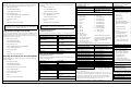
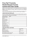
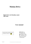
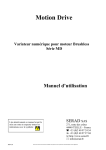
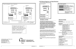
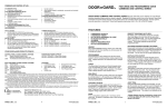
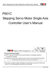
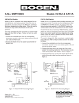
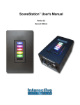
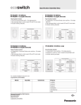
2000 Series
e/eM Style Keypad
Quick Start Guide
Circuit Board Diagram
Mounting the Keypad
Note: J3 is for
the external
relay board.
This Quick Start Guide is a reference document for experienced
installers only. Please refer to the more comprehensive information
supplied in the 2000 Series e/eM Keypad Installation and
Programming Manual located on our website at www.ieib.com. This
product is designed to be installed and serviced by security and lock
industry professionals.
LED/Sounder Indications
Indicator
Steady Red
Steady Green
Yellow Flashing Slowly
Solid Yellow
Alternating Red/Green
LED's Cycling Left to Right
LED's Cycling Right to Left
3 Rapid Beeps
Pair of Double Beeps
Single Double Beep
1 Long Beep, 1 Short Beep
1 Long Beep, 3 Short Beeps
1 Long Beep, 5 Short Beeps
6 Quick Beeps
Sounder ¼ sec on, ¼ sec off
Beep Every 2 seconds
Description
Door Locked
Door Unlocked (timed or latched)
Program Mode
Program Error or Error Lockout
Awaiting 2nd PIN of Two-Part User
Over Voltage Warning
Under Voltage Warning
Invalid Code
User Lockout Activated
User Lockout Canceled
Access Denied, User Disabled
Access Denied, User Lockout
Access Denied, Code Mismatch
Toggle Mode Activated
Audio Alert 1
Audio Alert 2
Document #: 6104402, Rev 1.0 D1e
For outdoor installations, use a weatherproof back box and seal the
wire entry locations with silicone and provide a drain hole. In
addition, use the anti-oxidant grease pack for the wire harness
connectors.
The 2000 Series e/eM Keypad has three operating modes: Standalone
Mode, Secured Series Front End Mode and Wiegand Front End
Mode. Below is a brief explanation of each mode. Refer to the
programming section on the opposite side for selecting each mode.
Specifications
10-30 VDC; 12-24VAC
VDC
VAC
10V: 82mA
12V: 110mA
Current requirements (Max)
30V: 115mA
24V: 140mA
Note: Does not include relay board.
Relay Contact Rating
2A @ 30VAC/DC (Main & Aux)
REX Input
Normally Open Dry Contact
Door Position Switch Input Normally Closed Dry Contact
Mechanical Dimensions
4.5" H x 2.75" W x 0.60" D
Environment
Indoor or Outdoor
Temperature Tolerance
-31°F to 151°F (-35ºC to 66°C)
Front End Cable Type
Stranded and Shielded
Front End Distance and Wire 1000 Ft. – 18AWG; 500 Ft – 20 AWG;
Gauge
250 Ft. – 22 AWG
The keypad is designed to be flush mounted using a standard singlegang electrical box. Mounting height can vary depending on
requirements. An appropriate range is typically between 48 and 52
inches on center off the floor.
Keypad Operating Modes
Specifications
Parameter
Voltage Requirements
Wiring an Electric Door Strike (Fail-Secure)
Wiring the REX and Door Position Switch
Standalone Mode:
Main Wire Harness (P2)
By default, the keypad is programmed for Standalone Mode. In
this mode, all the users and other programming options are
maintained within the keypad and no additional controller is
required. The lock and all other inputs and outputs are connected
directly to the keypad.
Secured Series Front End Mode:
In Secured Series Front End, an IEI Secured Series Controller is
required. The IEI Secured Series Controller maintains the users
and programming options and makes all the access control
decisions. The locking device and all inputs and outputs are
connected to the controller.
Wiegand Front End Mode:
Pin
1
2
3
4
5
6
7
8
9
10
Wire Color
Red
Black
White/Black
White/Yellow
Brown
White/Orange
White
Green
Blue
Gray
Description
V+ (Keypad Power)
V- (Keypad Power)
Wiegand Data 0/Secured Series Data
Wiegand Data 1/Secured Series Data
Request to Exit (REX)/LED1
Loop Common
Door Position Switch Input
Main Relay Normally Open
Main Relay Common
Main Relay Normally Closed
In Wiegand Front End, a separate Wiegand Access Control panel
is required. When you enter a code on the keypad it is then sent to
the control panel as Wiegand card data, depending on which
format you've programmed it for. The control panel maintains the
users and programming options and makes all the access control
decisions. The locking device and all inputs and outputs are
connected to the control panel.
Note: By default, the forced door and propped door outputs are
assigned to the audio alerts. When you power up the keypad for the
first time and door contacts are not connected, you may hear audio
alert #1 immediately followed by audio alert # 2 thirty seconds later.
If you are not using door contacts you must either short the white
and white/orange wires together or disable the audio alerts.
Secured Series Front End Wiring Diagram
Standalone Mode Wiring Diagrams
Wiring a Maglock (Fail-Safe)
Wiegand Front End Wiring Diagram
Auxiliary Relay Wire Harness (J2)
Pin
1
2
3
Wire Color
Green
Blue
Gray
Description
Aux Relay Normally Open
Aux Relay Common
Aux Relay Normally Closed
Technical Support: 1-800-343-9502
Changing the Master Code
The first step in setting up your keypad is to enter program mode
and change the master code. The default master code is 1234.
1.
2.
3.
Enter Program Mode.
Selecting Wiegand Front End Mode
Perform the following command sequence to select Wiegand Front
End Mode.
1.
Enter Program Mode.
Press: 99 # master code *
Press: 99 # master code *
Yellow LED Flashes Slowly
Yellow LED Flashes Slowly
Change Master Code.
2.
Select Wiegand Front End Mode
Press: 1032 # 0 # 1 # **
Yellow LED Flashes Slowly
Yellow LED Flashes Slowly
3.
Exit Program Mode
Press: *
Press *
The Yellow LED Stops Flashing
The Yellow LED Stops Flashing
Note: If you don't know the master code, perform the program
mode loopback to enter program mode: short the white/yellow,
brown and white wires together on power up.
Note: To change the keypad back to Standalone Mode enter:
1032 # 0 # 0 # ** while in programming mode.
Programming Users
Programming a Supervisor Code
Use the following command sequence to program a supervisor code,
which is stored user location 2. The supervisor is only allowed to
add, delete and disable users (all the commands in the Programming
Users section in the next column).
1.
Enter Program Mode.
Press: 99 # master code *
Yellow LED Flashes Slowly
2.
Change Master Code.
Press: 2 # supervisor code * repeat code *
(Standalone Mode Only)
The unit can hold up to 500 users. Codes are 1 to 10 digits in length.
Command/Action
Add Standard User (short)
Add Standard User with Specific
Unlock Time
Add Enhanced User
Add User to Trigger Specific
Outputs (Lock, OUT2-10)
Yellow LED Flashes Slowly
3.
Exit Program Mode
Press: *
The Yellow LED Stops Flashing
Selecting Secured Series Front End Mode
Perform the following command sequence to select Secured Series
Front End Mode.
1.
User Types (Enhanced Users)
(Standalone Mode Only)
When programming enhanced users enter the number in the user type
field (ie. 0 for toggle user).
Press: 1032 # 0 # 2 # **
Yellow LED Flashes Slowly
Duress User (8)
Yellow LED Flashes Slowly
3.
Delete User
User Types
Toggle User (0)
Standard User (1)
Lockout User (3)
Single Use Code (5)
Emergency User (7)
Enter Program Mode.
Press: 99 # master code *
2.
Disable User
Select Secured Series Front End Mode
Exit Program Mode
Press *
The Yellow LED Stops Flashing
Keys to Enter/Details
user location # code * code *
unlock time # user location #
code * code *
60 # user type # user location #
code * code *
59 # outputs # user location #
code * code * (1 = Lock, 2 =
OUT2, 3 = OUT 3, Etc)
56 # 0/1 # user location # **
(0 = enabled; 1 = disabled)
user location # **
Two-Part User Type A (9)
Two-Part User Type B (10)
Description
Latches the Lock Output
Standard Timed User
Locks Out other Users
Can only be Used Once
Can't be Locked Out
Activates Lock and Duress
Outputs
One half of two-part user
combination
One half of two-part user
combination
Programming Keypad Settings
(Standalone Mode Only)
Command/Action
Change Lock Output Time
Assign Outputs
Press: 1 # new master code * repeat code *
Exit Program Mode
Configuring Outputs
(Default settings are in bold)
Keys to Enter/Details
11 # time # 0 # ** (1-255 sec)
10 # virtual output # physical
output # **
Virtual Outputs
Physical Outputs
1 – Lock Output
1 – Main Relay
2 – Alarm Shunt
2 – Aux Relay
3 – Propped Door
3 – External Relay 1
4 – Forced Door
4 – External Relay 2
5 – OUT2
5 – External Relay 3
6 – OUT3
6 – External Relay 4
7 – OUT4
7 – External Relay 5
8 – OUT5
8 – External Relay 6
9 – OUT6
9 – External Relay 7
10 – OUT7
10 – External Relay 8
11 – OUT8
11 – Audio Alert 1
12 – OUT9
12 – Audio Alert 2
13 – OUT10
14 – Duress Output
Note: The keypad is equipped
15 – Panic Output
with only two relays. The Output
16 – Keypad Active Output
Expansion Module (2000-8EX) is
17 – Door Bell Output*
required to use additional
18 – REX Input Active
outputs.
19 – Door Loop Input Active
*Note: The Door Bell Output also works in both Front End Modes.
Disable Virtual Output
10 # virtual output # 0 # **
Disable Physical Output
10 # 0 # physical output # **
Programming the REX/Door
49 # outputs # input # **
Loop Outputs (Lock, OUT2-10) (Lock =1, OUT2 = 2, OUT3 = 3)
Set OUT2 Time Duration
12 # ttt # mmm # **
Set OUT3 Time Duration
13 # ttt # mmm # **
Set OUT4 Time Duration
14 # ttt # mmm # **
Set OUT5 Time Duration
15 # ttt # mmm # **
Set OUT6 Time Duration
16 # ttt # mmm # **
Set OUT7 Time Duration
17 # ttt # mmm # **
Set OUT8 Time Duration
18 # ttt # mmm # **
Set OUT9 Time Duration
19 # ttt # mmm # **
Set OUT10 Time Duration
110 # ttt # mmm # **
Set Propped Door Time
44 # time # 0 # ** (10-990 sec)
Set Forced Door Time
45 # time # 0 # ** (10-990 sec)
Notes: The default output settings are: Lock Output = Main Relay;
Alarm Shunt = Aux Relay; Forced Door = Audio Alert 1; Propped
Door = Audio Alert 2.
OUT2-10: ttt = time units; mmm = multiplier. Ex: “12 # 2 # 5 # **” =
10 seconds (2 time units multiplied by 5 seconds = 10 seconds). The
maximum value of ttt and mmm is 255 (255 x 255). The default
output times (Lock Output, OUT2-10) are 5 seconds. To toggle the
output enter 0 for both ttt and mmm; Ex: 12 # 0 # 0 # **.
Command 49 Input Number: 0 = REX; 1 = Door Loop.
Document #: 6104402, Rev 1.0 D1e
Command/Action
Change Keypad Options
Keys to Enter/Details
30 # option # setting # **
Option
0 – Audio Keypress Feedback
1 – Visual Keypress Feedback
2 – Auto Entry
3 – Error Lockout
4 – User Lockout
5 – Two-Part Users
6 – Keypad Backlighting
7 – Keypad Backlight Dimming
8 – REX Processing Select
9 – Red LED Dimming
Setting
0 = Disabled
0 = Disabled
0 = Disabled
0 = Disabled
0 = Disabled
0 = Disabled
0 = Disabled
0 = Disabled
0 = Only when
door closed
0 = Off when
backlighting dim
0 = Not when
lock latched
0 = Records IN
0 = Disabled
0 = Disabled
0 = Low
1 = Enabled
1 = Enabled
1 = Enabled
1 = Enabled
1 = Enabled
1 = Enabled
1 = Enabled
1 = Enabled
1 = Always
1 = Always On
10 – Door Loop Output
1 = Always
Processing
16 – Secured Series In/Out
1 = Records Out
18 – 8-Bit Burst Output
1 = Enabled
19 – WFE Red LED Select
1 = Enabled
20 – WFE Red LED Active
1 = High
State
21 – WFE Green LED Select
0 = Disabled
1 = Enabled
22 – WFE Green LED Active
0 = Low
1 = High
State
Note: WFE means Wiegand Front End
Change Keypad Parameters
32 # parameter # value # **
Parameter
Value
0 – Duress Output Duration
1 – 255 Seconds (default = 5)
1 – Panic Output Duration
1 – 255 Seconds (default = 5)
2 – Error Lockout Threshold
1 – 50 Attempts (default = 3)
3 – Error Lockout Duration
1 – 255 Seconds (default = 10)
4 – Auto-Entry Count
2 – 10 Digits (default = 4)
10 – Wiegand Format
1 – 8 (default = 1, 26-Bit)
11 – Wiegand Pulse Width
1 – 255 (default = 8, 160µS)
12 – Wiegand Interpulse Spacing 1 – 255 (default = 32, 640µS)
Note: See Wiegand Format Chart located in the manual on website.
Change Wiegand Parameters
34 # parameter # value # **
Parameter
Value
0 – Wiegand Site ID
Refer to Wiegand Format Chart
1 – Wiegand Group ID
Refer to Wiegand Format Chart
Note: The default setting for both settings is 0.
Resetting the Keypad
Command/Action
Keys to Enter/Details
Reset Defaults Only
40 # 00000 # 00000 # **
Reset Entire Keypad
46 # 00000 # 00000 # **
Note: This does not reset the keypad operating mode.
Technical Support: 1-800-343-9502