1
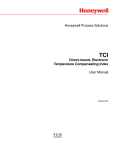
Honeywell Process Solutions
Turbo Corrector (TOC)
Supplement to :
Mini-AT User Manual
October 2010
V 3.02
Honeywell
2
www.honeywell.com
Turbo Corrector
Table of Contents
Introduction ....................................................................................................................... 5
TIB Connectors/Jumpers (location) ................................................................................... 6
Quick Start Guide .............................................................................................................. 7
Power Connection ............................................................................................................. 10
Backup Battery .................................................................................................................. 10
Serial Port Connection....................................................................................................... 11
Drawing, Connections for Mini-AT TOC with Slot Sensors ................................................12
Drawing, Connections for Mini-AT TOC with Blade Tip Sensors ....................................... 13
Solar Power Option ........................................................................................................... 14
Drawing, Solar Connections for Mini-AT TOC with Slot Sensors ...................................... 15
TIB Operation ....................................................................................................................16
Sensor Input Connection .................................................................................................. 18
Pulse Outputs ....................................................................................................................19
Alarms ............................................................................................................................... 20
4-20 milliamp output ..........................................................................................................21
Turbo Frequency Board .................................................................................................... 22
Live Graphing .................................................................................................................... 24
AAT Simulator ................................................................................................................... 26
AAT Linearization............................................................................................................... 28
Low Frequency Cut-Off...................................................................................................... 29
Upgrading TIB Firmware.................................................................................................... 30
TOC Item Codes ............................................................................................................... 37
Drawing, TOC Mini-AT Assembly Drawing......................................................................... 46
Drawing, TOC Mini-AT Parts Layout, No Options...............................................................48
Drawing, TOC Mini-AT w/ Optional TFB & Messenger Modem.......................................... 50
Drawing, TOC Mini-AT w/ Optional TFB & PT Board..........................................................52
Drawing, TOC Mini-AT w/ Optional TFB, Messenger Modem & PT Board......................... 54
Drawing, TOC 800 Parts Layout.........................................................................................56
Drawing, TOC 800 Parts List........................................... ..................................................57
Drawing, TOC 800 Simplified Wiring Diagram................................................................... 58
Drawing, TOC 800 2nd Pressure....................................................................................... 59
Drawing, TOC 800 Standard Switches............................................................................... 60
Drawing, TOC 800 Uncorrected Switch..............................................................................61
Drawing, TOC 800 Messenger Modem Option.................................................................. 62
Drawing, TOC 800 Protocol Translator (PT) Board Option................................................ 63
Drawing, TOC 800 4-20 mA Board Option......................................................................... 64
Drawing, TOC 800 Turbo Frequency Board (TFB) Option................................................. 65
Drawing, TOC 800 Single Pulse Alarm (SPA) Board Option.............................................. 66
Drawing, Installation for Div. 1 Hazardous Locations ........................................................ 68
Drawing, Installation for Div. 2 Hazardous Locations ........................................................ 69
Drawing, Wiring AAT with Barrier ...................................................................................... 70
3
Turbo Corrector
Revision List
1.00
1.01
2.00
3.00
3.01
Initial
Release
Modified: Various minor changes
Added: Live Graphing
p24
Parts Lists
p41-51
Modified: Firmware Upgrade Procedure
p27
Connection Drawings
p11-14
4-20mA Output
p21
Moved: Alarms
p19
TIB Diagram
p6
Modified: Various major changes that include:
- New layout for the TOC-800
- Assembly drawings for the TOC-800
- Redesign of input switch assembly
- New assembly drawings for TOC (Mini-AT Case)
- Info on new AAT Linearization feature
- Info on new Low Frequency Cut-off feature
- Updates to the Connection Drawings on Pg 12 & 13
Modified -Revised cover page
3.02
4
www.honeywell.com
Honeywell update
May 2002
June 2002
October 2003
February 2008
July 2008
October 2010
Turbo Corrector
Introduction
The Turbo Corrector is a full featured Mini-AT Electronic Volume Corrector with an internal
interface board called the Turbine Interface Board (TIB). The TIB accepts high-frequency
main and sense rotor signals from the Sensus Auto-Adjust Turbo-MeterTM (AAT), and calculates the adjusted volume based on the Sensus AAT algorithms. The TIB transmits lowfrequency adjusted and unadjusted volume pulses to the Mini-AT board. Depending on the
setting of item 182, pressure, temperature, and supercompressibility correction is applied to
either the Adjusted Uncorrected Volume, the Unadjusted Uncorrected Volume, or the Mechanical Uncorrected Volume (from the input reed switches) After each AAT calculation
cycle (usually 25,000 main rotor pulses), the TIB initiates a serial communications session
with the Mini-AT board to synchronize the values of mirrored item codes that coexist in both
circuit boards.
With newer firmware (2.20 and higher) and newer MasterLink (3.60 and higher),
The TIB is also capable of producing separate outputs for the following parameters:
- Low-frequency Adjusted Volume pulses (either 100 of 1,000 CF per pulse)
- Normal Alarm (Form-A, State-change)
- Abnormal Alarm (Form-A, State-change)
- Auxiliary Alarm, normally Pulsing Gas (Form-A, State-change)
- Buffered main rotor pulses
- Buffered sense rotor pulses
- 4-20 milliamp (analog) output for either Instantaneous Delta-A or Adjusted Vol Flow Rate.
When the optional Turbo Frequency Board (TFB) is installed:
- High-frequency Adjusted Volume pulses, which can be used for volume totalization or
instantaneous adjusted volume flow rate (Uncorrected)
Since the TOC’s main and sense rotors require constant power, which would deplete the
provided alkaline battery pack in a few days, an external power supply of +8.5 volts DC (+/0.5 volts) is always required. The external power is usually provided by an AC power supply, solar power supply or thermoelectric charger. The standard alkaline battery pack
serves as short-term battery backup in case of external power failure. Power supplies and
barriers for hazardous locations (Class 1, Divisions 1 & 2) are available.
MasterLink32 software is the primary user-interface to the Turbo Corrector. MasterLink32
provides the means to configure, calibrate, upload and download data. Live graphing and
storage of both rotor frequencies, Delta-A and Adjusted Flow Rate are provided.
5
Turbo Corrector
-
+
TB1
-
+
J2
J3
TB2
J4
+
+
TB3
TB4
TB5
J5
J6
JMP1
J9
TB6
+6V +6V
+
main
+
sense
J7 J8
J10
Diagram of the Turbine Input Board
(actual size)
Connector/Jumper
J2, J3
J4
J5
J6
J7
J8
J9
J10
JMP1
TB1
TB2
TB3
TB4
TB5
TB6
6
www.honeywell.com
Page 6
Purpose
Connection for TIB power
Connection for LCD display (not used in TOC)
RS-232 connection for external case connector
Firmware upgrade connection #2
and connection for Turbo Frequency Board
RS-232 connection to instrument
CMOS connection to instrument (not used)
Connection for AdjVol & UnadjVol pulse output to
Mini-AT J9
Firmware upgrade connection #1
Jumper to select RS-232 (J7) or CMOS (J8) port,
usually set on pins 1 & 2 (RS-232)
Form-A Adjusted Volume Pulse Output (LF)
4-to-20 mA output connection (external loop power
required)
Form-A output connections for Normal, Abnormal and
Auxiliary alarms
RS-232 connection for modem
Buffered Main and Sense rotor pulse output
Main and Sense rotor pulse input from turbine meter
Turbo Corrector
Quick Start Guide
The following steps will guide you to getting the TOC installed and operational.
1. Unpack the instrument and verify that there is no shipping damage. Also verify that
nothing is missing from the shipment.
2. Open the case door and make sure there are no loose connections or loose hardware.
3. Position the Turbo Corrector on the meter, making sure that the wriggler is aligned
properly. Bolt the Turbo Corrector to the meter using the mounting bolts and gasket provided.
4. Plug the memory battery connector into J26. You may initially see eight 6’s across the
LCD while the unit is initializing.
5. Install six new D-cell alkaline batteries if using the Alkaline Receptacle Pack. Hang the
battery pack on the screws of the battery hanger plate located inside the door. Install the
battery cover if using a disposable pack. Plug the main battery connector into J8 (J7 will
already be occupied by the TOC power cable).
6. Connect the external DC power wires to the field wiring terminal strip of the TOC power
cable.
7. Connect the sensor cable to the Turbo-Meter.
Mounting
Screws
Alkaline
Battery
Pack
TOC
Power
Cable
Field
Wiring
Terminal
Strip
TIB Power
Connections
Memory
Battery
J26 Memory
Battery
Connector
J7,J8
Power Cable
and
Main Battery
Connectors
7
Turbo Corrector
8. Verify that digits appear in the LCD display (usually all zeroes). Scroll through the
meter reader list by swiping a mag wand down the right side of the display window to verify
the instrument is operating.
Numeric Display
Mag Wand
(Start at top of label and
stroke downward to bottom
right corner)
9. Connect a standard serial cable from the TOC serial connector to a computer serial
port.
Warning: Connections to the RS-232 port are
permitted only in nonhazardous locations
Mini-AT
M E R C U R Y
Laptop Computer
CORRECTED VOLUME
METER READ LIST:
RS-232 Port
Serial Port
(i.e.COM1, COM2,)
TURBO CORRECTOR
Pressure
Connection
I/O Cable
P/N 40-1629
10. Run MasterLink32 software and use the “Set Instr. Date/Time via Computer” selection
in the Instrument Menu to set the date and time in the instrument. (Com Port and baud
rate may need to be set for the Computer Serial Port. Default baud rate is 9600.)
11. Use MasterLink32 to verify that company and site specific items are set properly,
especially item 98 (Meter Index Code), and items 863-868.
12. Using MasterLink32, run the Live Turbine Graph from the Graphs menu to determine if
the meter is operating correctly, i.e. rotor frequencies, Delta-A and flow rate.
13. Use the “Disconnect Link” function in the Instrument menu to return the Turbo Corrector back to corrector mode. Remove the I/O cable from the side of the instrument.
8
www.honeywell.com
Page 8
Turbo Corrector
14. Verify the Test Hand rotates in the counter-clockwise direction. If not, remove the
black mechanical index assembly and shift the lower bevel gear to the upper position for
CCW meter rotation.
Bevel Gear UP for CCW
15. Connect the Pressure line to the 1/4" NPT fitting at the side of the instrument.
1/4” NPT
fitting
Mini-AT
(front view)
Pressure
Line
16. Insert the slip-along fitting into the thermowell, and place the temperature probe into
the slip-along fitting, sliding the probe down until it nearly bottoms out in the thermowell
before tightening the slip-along nut
Temperature
Probe
Slip-Along
Fitting
Thermowell
17. At this point the instrument should be ready for operation.
9
Turbo Corrector
Power Connection
The Turbo Corrector requires 8.5 VDC (+/- 0.5 VDC) from an external source to operate.
The standard external source is an AC-to-DC power supply (Div. 1 locations require barriers) with an alkaline battery as backup power. Alternatively, solar power is available, (location dependent).
Note: Damage to the internal Power Distribution Cable will result if external power
exceeds 9.0VDC.
When using the standard power supply, the output is connected to the Turbo Corrector
power cable mounted to the left side of the case using the provided terminal strip. The
Turbo Corrector power cable should already have one connection plugged into J7 of the
Mini-AT main board and the other connection plugged into J2 of the TIB. The alkaline
battery pack plugs into J8 of the Mini-AT board.
TOC
Power
Distribution
Battery
Terminal
Strip
Power Components
Battery Backup
The Turbo Corrector with DC power supply has the option of two battery backup strategies;
a short term backup strategy and a long term backup strategy. The short-term strategy
(using power cable 40-2809-1) will allow the Mini-AT, TIB, and sensors to remain powered
for approximately 48 hours. The long-term strategy (using power cable 40-2809-2) will
power the Mini-AT for approximately 3 years. In the long term strategy, the TIB and sensors will not be powered by the backup battery.
The standard configuration for the Turbo Corrector is the short-term strategy. The long
term configuration is available as an option.
Note: It is highly recommended that an Uninterruptible Power Supply (UPS) be used in
conjunction with the DC power supply in the short-term configuration to compensate for
possible power failures.
10
Page 10
www.honeywell.com
Turbo Corrector
Serial Connection
The TIB has three serial port connections:
- one to connect the TIB to the Mini-AT board to allow internal communications to the MiniAT board (at J7)
- one to connect the TIB to the case connector for a local serial connection (at J5)
- one to connect the TIB to remote communications device, modem, radio, etc. (at TB4).
Normal serial communications to the Mini-AT are routed through the TIB at J5.
MasterLink32 can communicate with either the Mini-AT or TIB depending upon which is
selected in the MasterLink32 establish link dialogue box. Item 272 in the Mini-AT board
(TB2) and item 856 in the TIB (J7) must be set to the same baud rate, which defaults to
9600 for both. Also, the settings at items 857 (External Port Baud Rate (J5), default 9600)
and 858 (Modem Port Baud Rate (TB4), default 2400) must match the host baud rate for
the device being used.
See the drawings on the next two pages more details on various cable connections.
Modem Port
Connection TB4
(baud rate setting
at item 858)
Mini-AT
serial port
to TIB port
Connection TB2
(baud rate setting
at item 272)
External Case
Connector Port
Connection J5
(baud rate setting
at item 857)
TIB port to
Mini-AT port
Connection J7
(baud rate setting
at item 856)
External Case
Connector
Serial Port Connections
11
Turbo Corrector
12
www.honeywell.com
Page 12
TOC w/ Slot Sensors Connection Drawing
Turbo Corrector
TOC w/ Slot Sensors Connection Drawing
13
Page 13
Turbo Corrector
Solar Power Option
Solar power consists of the solar panel, re-chargeable battery, solar charger, and voltage
regulator. Power from the solar panel is cabled into the case to the solar charger. The
solar charger prevents over-charging of the battery while providing power to the battery and
the Turbo Corrector. Installation location and panel size must be taken into consideration
to determine if the solar panel will generate enough power for the Turbo Corrector. Several
panel and battery configurations are available.
Short-term is the only power back-up strategy available for the solar power option. If
power from the solar panel is interrupted, a fully-charged battery can generally last 3.5 and
15 days, depending upon the size of the battery in the solar power system.
Solar
Charging
Unit
Battery
Shelf
Voltage
Regulator
14
www.honeywell.com
Solar Power Connection (800 Series Case)
Turbo Corrector
TOC Solar Power Connection Drawing
with Slot Sensors
15
Page 15
Turbo Corrector
Turbine Interface Board Operation
The basic purpose of the Turbine Interface Board (TIB) is to accept high-frequency pulses
from the main and sense rotor sensors of the Auto-Adjust Turbo-Meter (AAT), compute the
Sensus algorithms, and output low-frequency adjusted and unadjusted volume pulses to J9
of the Mini-AT main board. The value of each of the low-frequency pulses is determined by
the setting at item 098 (Meter Index Code). The TIB will check the main and sense rotor
frequency every 1 second and send Adjusted and Unadjusted volume pulses when the
volume accumulated has reached the value at item 098.
The Adjusted Volume (VA) and Unadjusted Volume (VU) are calculated as follows:
VA =
Where:
PM PS
KM KS
P
VU = KM
MO
VA = Adjusted Volume
VU = Unadjusted Volume
PM = Main Rotor Pulses
PS = Sense Rotor Pulses
KM = Main Rotor Factor
KS = Sense Rotor Factor
KMO = Mechanical Output Factor
The calculated values of Adjusted and Unadjusted volume should be very close to each
other. However, flow conditions, mechanical problems and electrical problems can cause a
deviation between the two. This deviation is calculated by the TIB as a percentage. This
percent deviation from factory calibration is known as Delta A (DA). The value of Delta A is
updated every Auto-Adjust cycle. The Auto-Adjust cycle is defined as every 25,000 main
rotor pulses or every 8.5 minutes, whichever occurs first.
Delta A is calculated as follows: ∆A =
100
PM
KM
PS
KS
Where:
16
- Abar
-1
DA = % Deviation from Factory Calibration
Abar = Average Relative Adjustment at factory calibration
PM = Main Rotor Pulses
PS = Sense Rotor Pulses
KM = Main Rotor Factor
KS = Sense Rotor Fac
www.honeywell.com
Turbo Corrector
The TIB has certain functional characteristics that result from certain input conditions of the
Auto-Adjust Turbo Meter. These characteristics are listed below.
Condition
Main rotor pulses received from meter are less
than the value programmed into item 406 (AAT Low
Flow Cut-Off Hz.) Default = 3 Hz.
Result
Item 881 (Main Rotor Frequency) is forced to zero
Sense rotor pulses received are less than 2 per
second (2 Hz.)
Item 882 (Sense Rotor Frequency) is forced to zero
Main rotor input receives pulses but sense rotor
frequency is zero
TIB calculates Un-adj volume and sends to the Mini-AT
board as Adj volume. Delta-A is fixed at -Abar
Sense rotor input receives pulses but main rotor
frequency is zero
No volume pulses are sent to the Mini-AT board.
Delta-A is fixed at -100 -Abar (a value of about -110)
TIB Functional Characteristics
The TIB has the ability to establish a serial link with the Mini-AT board for exchange of item
data. There are two triggers in which this data exchange occurs. The first is directly after a
local or remote serial connection to the Mini-AT board has ended. This is done mainly for
the TIB to read any configuration changes that may have been made to the Mini-AT. The
second serial trigger occurs on every Auto-Adjust cycle, i.e. 25,000 main rotor pulses or 8
1/2 minutes, whichever occurs first.
The TIB reads and updates the following mirrored items (having the same item number)
from the Mini-AT during a serial link, triggered by a local or remote serial connection.
049 Battery Low Volt Limit
864 Turbine Meter Size
050 Shutdown Voltage Limit
865 KM Meter Factor
092 UnCor Volume Units
866 KS Meter Factor
097 UnCor Vol Display Res
867 Abar Meter Factor
098 Meter Index Rate
868 KMO Meter Factor
115 Pulser Output Time
870 Turbine Sensor Type
165 RBX Alarm Enable
871 TIB 4-20 Out Config
170 Protocol Code A
872 Normal Alarm Limit
171 Timeout Delay 1
873 Abnormal Alarm Limit
172 Timeout Delay 2
879 Normal Alarm Dead Band
200 Site ID Number
880 Abnormal Alrm Dead Band
201 Site ID Number Part 2
884 Adj Flow 20mA Value
861 TIB Serial Number
885 Adj Flow 4mA Value
863 Meter Serial Number
889 High Freq Out Max Freq
The TIB writes the following items to the Mini-AT during a serial link, triggered by an AutoAdjust cycle.
853 Turbine Adj Flow Rate
874 Pulsing Gas Alarm
854 Turbine UnAdj Dial Rate 875 TIB Internal Fault
859 AdjVol Pulses Waiting
881 Main Rotor Frequency
860 UnAdjVol Pulses Waiting 882 Sense Rotor Frequency
862 TIB Firmware Version
883 Adjusted Volume Pulses
869 Instantaneous Delta A
887 8515 Firmware Version
Page 17
17
Turbo Corrector
Original Configuration
In order to allow the instrument to function in Turbo Corrector mode (i.e. TIB periodically
updating Mini-AT items), item 855 must be set to Turbo Corrector Mode. By enabling this
mode, and with the default selection of item 182 (Input Volume to Corrector) set to TIB Adj
Vol (SW3), volume correction is made from the adjusted volume pulses sent from the TIB
to Mini-AT board at J9. Also, the numerous Serial Log Triggers generated by the TIB’s
serial connection are automatically disabled to keep Audit Trail memory from filling up with
serial access logs from the TIB.
Input Parameters from the Auto-Adjust Turbo-Meter
It is critical that the following Turbo Corrector items are properly configured with parameters
from the Auto-Adjust Turbo-Meter. Without properly configuring these items, the Turbo
Corrector will produce incorrect volume information.
The items are:
863 Meter Serial Number
864 Turbine Meter Size
865 Km Meter Factor - pulses per cubic foot of the main rotor
866 Ks Meter Factor - pulses per cubic foot of the sense rotor
867 ABar Meter Factor - average amount of adjustment from factory calibration
868 Kmo Meter Factor - pulses per cubic foot of the mechanical output (unadjusted)
The values for these items are found on the Turbo-Meter’s serial plate with the exception of
KMO Meter Factor, which can be found on the factory calibration data sheet. Note: It is
very important that item 868 (Kmo Meter Factor) is configured with the KMO value.
If not, the TIB will compute inaccurate values for Unadjusted Volume.
Sensor Input Connection
The main and sense rotor signals are to be connected from the Turbo-Meter’s slot sensors
to TB6 of the TIB board using the supplied 4-foot Sensor Cable (p/n: 40-2833-1). An optional 25 foot cable is also available for remote mounting locations (p/n: 40-2833-25). If the
Turbo-Meter incorporates blade-tip sensors, a different input cable is require since the
connector requires six pins instead of the normal five pins. For blade-tip meters, use input
cable p/n 40-3033.
Sense Rotor +
(white)
Sense Rotor (orange)
Main Rotor +
(red)
Main Rotor (black)
Sensor Input
Cable
18
Shield wire
(clear)
www.honeywell.com
Page 18
Sensor Cable Connections
Turbo Corrector
Pulse Outputs
In addition to the Mini-AT’s standard pulse outputs, the TIB has 3 pulse outputs of it’s own.
The Pulse Outputs are as follows:
TB1:
Low-frequency Adjusted Volume Output (Form A, scaled to units set at item
098)
TB5:
High-frequency Buffered Main Rotor meter pulses (Form-A)
High-frequency Buffered Sense Rotor meter pulses (Form-A)
Output Pulse Specifications
1.
2.
3.
All outputs are isolated from ground and each other.
The wetting voltage is rated for DC only, from 3.0 volts to 30.0 volts (15.0 volts per CSA).
Observe polarity.
The pulser circuits will sink up to 5 milliamperes (DC).
Pulse Collection Device
+
-
+
DC
Power
Pulse
Counter
-
TIB
+ -
Pulse
Output
Pulse Connection Circuit
19
Turbo Corrector
Alarms
In addition to the standard Mini-AT Alarms (listed in the Mini-AT Operator’s Guide) there are
four alarms for the TOC. These alarms exist in the Turbine Interface Board (TIB) and are
transferred to the Mini-AT on the AAT calculation cycle, where they are date & time-stamped
into the Alarm Logger.
Alarm Description Item#
Alarm Code
Dead Band Item#
Alarm Limit Item#
Pulsing Gas Alarm
874
.E.8.7.4.
Fixed in Firmware
Fixed in Firmware
TIB Internal Fault
875
.E.8.7.5.
None
None
Normal Alarm
877
.E.8.7.7.
879
872
Abnormal Alarm
878
.E.8.7.8.
880
873
Alarm Outputs
The Turbo Corrector will generate a Form-A output on every new alarm. The alarm outputs
are available on TB3 of the Turbine Interface Board. There are three outputs available: the
Normal alarm, Abnormal alarm and Aux out. The Aux out channel is used for the low battery,
internal fault and pulsing gas alarms. At the occurrence of any alarm, the appropriate output
will latch into the ON or closed state and remain in that state until cleared by RBX, software or
firmware.
Initial Recommended Alarm Configuration
Alarm Limits
Operating Conditions
Normal
(Item 872)
Abnormal
(Item 873)
Normal
(Item 879)
Abnormal
(Item 880)
Meter flow rate 50% to 100% of rated
capacity. Pressures over 275 psi.
+/- 0.5%
+/- 2.0%
0.05%
0.2%
Meter flow rate 20% to 100% of rated
capacity. Pressures over 275 psi.
+/- 0.75%
+/- 1.0%
+/- 3.0%
+/- 3.0%
0.075%
0.1%
0.3%
0.3%
Meter flow rate 20% to 100% of rated
capacity. Pressure range 50 to 275 psi.
+/- 1.25%
+/- 1.5%
+/- 1.75%
+/- 4.0%
+/- 4.0%
+/- 4.0%
0.125%
0.15%
0.175%
0.4%
0.4%
0.4%
Meter flow rate 5% to 100% of rated
capacity. Pressures less than 50 psi.
+/- 2.0%
+/- 5.0%
0.2%
0.5%
+/- 2.5%
+/- 5.0%
0.25%
0.5%
Use these values if you can’t decide on
any of the above
+/- 2.0%
+/- 5.0%
0.2%
0.5%
TOC Alarms
20
Dead Band
www.honeywell.com
Page 20
Turbo Corrector
4-20 milliamp output
In addition to the pulse outputs, the Turbo Corrector has a single 4-20 milliamp output channel
available at TB2. The TIB updates the 4-20mA output every 5 seconds. The channel is
configurable to output either Delta-A or Adj Vol Flowrate. The selection is made at item 871
(TIB 4-20 Out Config). The limits for Delta-A output are fixed at -5% (4ma) and +5% (20ma).
The Adj Vol flow rate limits are user selected at items 884 (20ma) and 885 (4ma). The output
requires loop power, and must have a minimum of 9VDC across the + and - terminals under
any load condition. 24 volts DC loop power is typical.
The 4-20 milliamp output function can be verified by changing the selection at item 871 and then
disconnect the serial link. Depending on the setting, the 4-20 mA output can provide a constant
4, 12 or 20mA signal for verification or calibration purposes. Note, disconnect link after each
change at allow the configuration to take affect. After verification, Item 871 should be set back
to either Delta-A or Adj Vol Flowrate for the output to function normally.
TB2 4-20ma
output
TB1 Adjusted
Volume output
TB3 Alarm
outputs
TB5 Main and
Sense rotor
buffered outputs
(high frequency)
Pulse and 4-20mA Output Connection Locations
24VDC
Supply
+
+
TIB
4-20mA
Receiver
(w/o powered loop)
+
4-20mA
Receiver
(w/ powered loop)
TIB
- +
4-20
output
4-20mA Output Connections
- +
4-20
output
21
Page 21
Turbo Corrector
Turbo Frequency Board (TFB)
The Turbo Frequency Board (TFB) is an optional accessory that outputs a proportional
signal for Adjusted Volume flow, providing up to 1,000 pulses per second at the specified
100% flow rate of any Auto-Adjust Turbo-Meter. The high frequency output is accurately
scaled so that each pulse can be accumulated for remote volume readings (either Ft3 or
m3) or may be used as a flow rate signal. A maximum frequency parameter (Item 889)
permits the user to select the desired number of pulses that will correspond to the maximum rated flow of the meter. Choices for maximum frequency are 50, 100, 200, 500 or
1,000 hertz. The turbine meter size (Item 864) and the meter index units (Item 098) must
be properly configured to obtain the proper frequency from the TFB.
The Turbo Frequency Board plugs into the TIB at connector J6 and is secured by two mounting
screws. The TFB receives its power and input signal through J6 while providing the output
frequency at TB1 on the Turbo Frequency Board. The frequency output must be wetted by a
3-15 volts DC receiver for proper operation.
The TFB includes a red LED (D1) that blinks at a slow rate (once per second) when power is
first applied and while waiting for a valid packet of data. The faster rate (7 times per second)
indicates that a valid packets have been received and an output frequency has been transmitted
to the opto-coupler. During normal operation, the LED will always blink at the faster rate.
LED (D1)
Mounting
points
connection
to TIB J6
(reverse side of
board)
Frequency out
connection (TB1)
22
www.honeywell.com
Page 22
Turbo Frequency Board (installed)
Turbo Corrector
Turbo Frequency Board Pulse Factors
Output Frequency @ Max. Flow Rate
Meter
(English)
50 Hz.
100 Hz.
200 Hz.
500 Hz.
1000 Hz.
Size Blade Pulses Ft3 per Pulses Ft3 per Pulses Ft3 per Pulses Ft3 per Pulses Ft3 per
(in.) Angle per Ft3 pulse per Ft3 pulse per Ft3 pulse per Ft3 pulse per Ft3 pulse
Model
AAT-18
AAT-30/35
AAT-60
AAT-140
AAT-27
AAT-57
AAT-90
AAT-230
4
6
8
12
4
6
8
12
45O
45O
45O
45O
30O
30O
30O
30O
AAT-18
AAT-30/35
AAT-60
AAT-140
AAT-27
AAT-57
AAT-90
AAT-230
0.100000
0.200000
0.333333
0.833333
0.166667
0.333333
0.500000
1.250000
20
10
6
2.4
12
6
4
1.6
0.050000
0.100000
0.166667
0.416667
0.083333
0.166667
0.250000
0.625000
40
20
12
4.8
24
12
8
3.2
0.025000 100 0.010000 200 0.005000
0.050000 50 0.020000 100 0.010000
0.083333 30 0.033333 60 0.016667
0.208333 12 0.083333 24 0.041667
0.041667 60 0.016667 120 0.008333
0.083333 30 0.033333 60 0.016667
0.125000 20 0.050000 40 0.025000
0.312500 8 0.125000 16 0.062500
Output Frequency @ Max. Flow Rate
Meter
(Metric)
Model
10
5
3
1.2
6
3
2
0.8
50 Hz.
100 Hz.
200 Hz.
500 Hz.
1000 Hz.
Size Blade Pulses m per Pulses m per Pulses m per Pulses m per Pulses m3 per
(mm) Angle per m3 pulse per m3 pulse per m3 pulse per m3 pulse per m3 pulse
3
100
150
200
300
100
150
200
300
45O
45O
45O
45O
30O
30O
30O
30O
350
175
105
45
210
105
70
28
0.002857
0.005714
0.009524
0.022222
0.004762
0.009524
0.014286
0.035714
3
700
350
210
90
420
210
140
56
0.001429
0.002857
0.004762
0.0111111
0.002381
0.004762
0.007143
0.017857
3
1400
700
420
180
840
420
280
112
0.000714
0.001429
0.002381
0.005556
0.001190
0.002381
0.003571
0.008929
3
3500
1750
1050
450
2100
1050
700
280
0.000286
0.000571
0.000952
0.002222
0.000476
0.000952
0.001429
0.003571
7000
3500
2100
900
4200
2100
1400
560
0.000143
0.000286
0.000476
0.001111
0.000238
0.000476
0.000714
0.001786
Table 3
Volume Per Pulse for various meter sizes and Frequencies
Page 23
23
Turbo Corrector
Live Graphing (Turbine Related Items)
The Turbo Corrector, via MasterLink has the capability to graph turbine related items. The
graphable items are Main Rotor Frequency, Sense Rotor Frequency, Instantaneous Delta
A, Adjusted Volume Flow Rate and High Frequency Adjusted Volume. These items can be
graphed one at a time, or up to a maximum of four. Each item has a configurable scale,
line color and line style. The graph is ‘live’ with a configurable update interval and viewing
interval. The figure below shows a sample graph with four items on the graph. Notice that
the last updated value of each item is shown as a numeric value in a display box at the
bottom of the graph.
The graph window also has a tool bar at the top that is used to customize the graph. The
toolbar can be used to change background colors, show gridlines, zoom in or out and show
the graph in 3D. The Graph Setup button at the bottom of the graph will pull up the Graph
Configuration screen, as outlined on the next page. Clicking the Reset Style button will
reset the configuration to default. Clicking the Close button will exit the Live Graph mode.
Live Graph Display
24
www.honeywell.com
Turbo Corrector
Live Graph Configuration
The live graph can be setup using the Graph Configuration. The Y Axis Item column is
used to choose which items are to be graphed. Clicking on the drop down arrow will cause
a list of items to appear. Simply select the desired item from the list. If only one or two
items are to be graphed, select those items for the first one or two and change the remaining items to None. The Y Minimum and Y Maximum columns are use to select a range of
values to scale on the graph. The Color and Line Style columns are used to configure the
type of line to be displayed on the graph.
Other graphing options are set in the lower Options portion of the Setup screen. The
Reading Interval is used to set up how often the software interrogates the Turbo instrument
for the information that is being graphed. This can be set from 1 to 30 seconds. The Xaxis Width configures how much of a time interval to show on the graph. The default is 30
seconds. There are also two check boxes. When checked, the Show ToolBar displays the
toolbar at the top of the graph window. The second, Show Data Points on Lines displays a
dot on the graphing lines for each retrieved data value.
Live Graph Configuration
25
Turbo Corrector
AAT Simulator
A compact, portable device is available for testing the electronic functions of a Turbo Corrector. The AAT Simulator (p/n 40-2835) will simulate main and sense rotor signals from
the AAT. Two rocker switches are provided, a two position switch to change the main rotor
frequency, and a three position switch for changing the sense rotor frequency, which will in
turn, affect the Delta-A value calculations. The simulator is connected to the Instrument
through the sensor input cable and is powered by a standard, external Mercury battery
pack.
Connection to
standard
Mercury
battery pack
Connection to
Sensor Input Cable
26
www.honeywell.com
Turbo Corrector
Turbine Data
to be entered
into TIB
Sense Rotor
Switch
Main Rotor
Switch
Page 27
27
Turbo Corrector
AAT Linearization
Starting with firmware version 2.20, a more accurate flow rate calculation (especially at low
flows) can be obtained when additional meter calibration data are used. The additional
calibration data may contain up to six flow rates and up to four pressures. Based on live
flow rates and live pressure readings measured by the TOC, a linear interpolation method
is used to correct the error at live flow rates that fall between calibration flow rate data
points. Live pressure readings are used to select the closest pressure calibration table
stored within the instrument. In addition to linearization corrections to Adjusted and Unadjusted volumes, Delta-A calculations are also adjusted using the calibration data.
Linearization adjustments are applied at each volume calculation, i.e., every 1-second. The
‘working linearization table’ is updated based on live pressure at each Delta-A correction
cycle, which is usually every 25,000 main rotor pulses or 8-1/2 minutes, which ever occurs
first. The 1-second volume adjustment computations use the most recently computed
linearized meter factors. However, Delta-A is linearized using the average flow rate of the
most current AAT cycle.
Six new ‘diagnostics’ items were created and may be optionally placed in the audit trail for
logging:
Item 393 Minimum Delta-A (linearized) for log interval
Item 394 Maximum Delta-A (linearized) for log interval
Item 395 Minimum Unadjusted meter factor (linearized) for log interval
Item 396 Maximum Unadjusted meter factor (linearized) for log interval
Item 397 Minimum Adjusted meter factor (linearized) for log interval
Item 398 Maximum Adjusted meter factor (linearized) for log interval
See the Item Code Listing section in this manual for mor information of these items.
A text file (with a file extension of “.LIN”) is used to send calibration data for a particular
meter, to the TOC. The linearization data in the file is expressed as a “percent error”. The
Turbine Meter Size (item 864), displayed as ”AAT-27", “AAT-35/30”, “AAT-57”, etc., is automatically set when the .LIN file is loaded. MasterLink software will also automatically
handle the conversion if the file contains metric volume units.
Sending calibration data in either direction (between a .LIN file and the instrument) is
handled in MasterLink’s Transfer menu. An interactive read/write of AAT Linearization
parameters is handled in MasterLink’s Setup menu. An example of this setup form is
shown on the next page.
NOTE: To take advantage of the AAT Linearization feature, calibration data beyond
what’s supplied on the AAT meter serial plate is required. Data similar to what’s
shown in the sample form on the next page is needed. Contact Sensus Metering
Systems for information on how to obtain and use this calibration data.
28
www.honeywell.com
Turbo Corrector
AAT Linearization Setup Form
Low Frequency Cut-Off (Main Rotor)
Starting with firmware version 2.20, item 406 (AAT Low Flow Cut-Off Hz) was added to
allow the user to specify a low flow cut-off for the main rotor only. The cut-off is expressed
in Hertz as an integer value from 1 to 40, and defaults to the previously hard-coded value
of 3 Hz. Main rotor volume that comes into the TIB at a frequency at or above the 406
value is accepted, but volume that comes in at a frequency below 406 is not registered.
This feature is to help reduce or eliminate the processing of no-net resonant flows, such as
main rotor oscillation during no flow conditions.
29
Turbo Corrector
Upgrading TIB firmware
1. Items Required
PC with Windows 95/98 OS (or higher)
Firmware Upgrade Manager software (FWUM) version 2.1101 or later Install Firmware Upgrade Manager software, which is usually provided on the MasterLink32 CD
under the “Bonus Software” folder. NOTE: Always install the program “Mercury
Calculator” prior to Firmware Upgrade Manager when working on a Windows XP machine.
TIB Firmware file for Controller 103 (U15) (TIBxxxxx.tbx) and TIB Firmware file for
Controller 8515 (U9) (T8Bxxxxx.t8x
Mercury Programming Adapter (MPA) p/n 40-2620, with version 1.1002 firmware (or
higher).
RS-232 serial I/O cable, p/n 40-1629
TIB board, p/n 40-2708 (may be part of a TOC or TOM assembly)
TOC Power cable p/n 40-2809-1 (with battery or DC power connected) or TOM Power
cable p/n 40-2812 (with battery or DC power connected)
30
www.honeywell.com
Page 30
Turbo Corrector
2.
2.1
Programming the TIB:
Programming both Microcontrollers (103 & 8515) with Mercury MPA
1.
Connect MPA to PC serial port via the 40-1629 cable.
2.
Connect MPA ribbon cable (10-pin header conn) to TIB (J10) port (red wire to
pin #1).
PC running
FWUM
version
2.1101
3.
Start Mercury Firmware Upgrade Manger and select “TIB“ from icon toolbar.
A Dialog box appears to explain the sequence of connecting the MPA ribbon
cable during programming.
Page 31
31
Turbo Corrector
Note: The TIB requires the firmware in the 103 Microcontroller (U15) to be erased before
the firmware in the 8515 Microcontroller (U9) can be programmed. For this reason, the
MPA is to be plugged into J10 first to erase the 103 Microcontroller (U15) firmware before
changing to J6 for programming the 8515 Microcontroller (U9) firmware.
32
4.
Send … \ tibXXXXX.t8x” file (use file browser if required).
5.
FWUM erases, the main program, then disconnects from the MPA.
www.honeywell.com
Page 32
Turbo Corrector
6.
Unplug the MPA from J10 and plug it into J6 so FWUM can upgrade the 8515
firmware.
33
Page 33
Turbo Corrector
34
7.
After the 8515 firmware upgrade is complete, unplug the MPA cable for J6 and plug
it back into J10. Chose the .
8.
Select the “tbx“ file from list box and click OK to begin upgrading the main TIB
firmware.
www.honeywell.com
Turbo Corrector
9.
After both TIB processors are upgraded, exit FWUM.
35
Page 35
36
www.honeywell.com
Turbo Corrector
TOC Item Code List
( * indicates TIB only items )
Item
No. Item Name
Description
182
Input Vol to Corrector
Code (0-2) selects which type of uncorrected volume
pulses used as the input to J9 of the Mini-AT main
board, to produce corrected volume.
Select:
0 – Unc mech. Switch (Sw 1 & 2)
1 – TIB Adj Vol Pulse (Sw3) Default
2 – TIB Unadj Vol Pulse (Sw4)
393
Cal Delta-A Min
The minimum, linearized value of Delta-A that has
occurred during the current log interval (defined at item
202). This parameter, along with all linearizations diagnostic items (items 393-398) are helpful in verifying the
performance of the AAT Linearization feature, especially
when all six items are logged in the expanded audit trail.
Default = 0.0000
394
Cal Delta-A Max
The maximum, linearized value of Delta-A that has
occurred during the current log interval (defined at item
202). This parameter, along with all linearization diagnostic items (items 393-398) are helpful in verifying the
performance of the AAT Linearization feature, especially
when all six items are logged in the expanded audit trail.
Default = 0.0000
395
Meter Factor Unadj Min
The minimum, linearized value of unadjusted meter
factor that has occurred during the current log interval
(defined at item 202). This parameter, along with all
linearization diagnostic items (items 393-398) are helpful
in verifying the performance of the AAT Linearization
feature, especially when all six items are logged in the
expanded audit trail.
Default = 0.0000
396
Meter Factor Unadj Max
The maximum, linearized value of unadjusted meter
factor that has occurred during the current log interval
(defined at item 202). This parameter, along with all
linearization diagnostic items (items 393-398) are helpful
in verifying the performance of the AAT Linearization
feature, especially when all six items are logged in the
expanded audit trail.
Default = 0.0000
37
Turbo Corrector
Item
No. Item Name
38
Description
397
Meter Factor Adj Min
The minimum, linearized value of adjusted meter
factor that has occurred during the current log interval
(defined at item 202). This parameter, along with all
linearization diagnostic items (items 393-398) are helpful
in verifying the performance of the AAT Linearization
feature, especially when all six items are logged in the
expanded audit trail.
Default = 0.0000
398
Meter Factor Adj Max
The maximum, linearized value of adjusted meter
factor that has occurred during the current log interval
(defined at item 202). This parameter, along with all
linearization diagnostic items (items 393-398) are helpful
in verifying the performance of the AAT Linearization
feature, especially when all six items are logged in the
expanded audit trail.
Default = 0.0000
406
AAT Low Flow
Cut-Off Hz.
The low-end frequency of the main rotor signal at which
the TIB assumes a value of zero, until exceeded. This
user specified parameter is to help reduce or eliminate
processing of no-net resonant flows, such as main rotor
oscillation during no flow conditions.
Range: 1 - 40 Hz.
Default = 3 Hz.
850
Adjusted Volume
Totalized Adjusted Uncorrected Volume. This value is
scaled to volume units selected at Item 092 and to the
number of digits defined by Item 097.
Default = 00000000
851* Hi Res Adjusted Volume
Fractional portion of Item Code 850 (Adjusted Volume)
displayed in units of ft3 or m3. This item is continuously
updated until it reached the value of adjusted volume
units at Item 092. At that point, item 850 is updated and
item 851 is reset to zero.
Default = 0.000000
852
Totalized Unadjusted Uncorrected Volume. This value is
scaled to volume units selected at Item 092 and to the
number of digits defined by Item 097.
Default = 00000000
UnAdjusted Volume
www.honeywell.com
Turbo Corrector
Item
No. Item Name
Description
853
Turbine Adj Flow Rate
The current instantaneous rate of flow for Adjusted Volume (850), expressed in the selected Adjusted Volume
units (ft3 or m3) per hour. The value is updated every
1-second in the TIB and transferred to the Mini-AT board
on every AAT Cycle serial link. When accessed, the unit
will display the most recently computed value.
Default = 0.00
854
Turbine UnAdj Dial Rate
The current instantaneous rate of flow for Unadjusted
Volume (852), expressed in the selected Unadjusted
Volume units (ft3 or m3) per hour. The value is updated
every 1-second in the TIB and transferred to the Mini-AT
board on every AAT Cycle serial link. When accessed,
the unit will display the most recently computed value.
Default = 0
855
Turbine Configuration
Item used to determine the configuration of the instrument, A selection of ‘0’ at item 855 is used for standalone Mini-AT and Turbo Monitor units. A selection of ‘1’
at item 855 is used for Turbo Correctors and enables
serial communication between the TIB and Mini-AT
mainboards. FYI - Normally, serial communications with
the Mini-AT board passes through the TIB.
Select:
0 – Turbine Support Off
1 – Turbo Monitor Mode
856* Corrector Baud Rate
Code
Code (0-7) to select the baud rate at TIB port J7. This
port is normally used to make a serial link to the Mini-AT
in the Turbo Corrector mode and is generally not used in
the Turbo Monitor mode. A communication’s error will
occur if this baud rate does not match the baud rate of
TB2 of the connected Mini-AT board.
Select:
0 – 9600 Default 4 – 600
1 – 4800
5 – 300
2 – 2400
6 – 19200
3 – 1200
7 – 38400
39
Turbo Corrector
Item
No. Item Name
40
Description
857* Ext Case Conn
Baud Rate Code
Code (0-7) to select the baud rate at TIB port J5. This
port is normally used to make a local serial connection. A
communication’s error will occur if this baud rate does not
match the baud rate of the connected external device.
Select:
0 – 9600 Default
4 – 600
1 – 4800
5 – 300
2 – 2400
6 – 19200
3 – 1200
7 – 38400
858* Modem Port
Baud Rate Code
Code (0-7) to select the baud rate at TIB port TB4. This
port is normally used to make a serial connection to an
external modem. A communication’s error will occur if the
baud rate does not match the baud rate of the external
modem (or other serial device).
Select:
0 – 9600
4 – 600
1 – 4800
5 – 300
2 – 2400 Default
6 – 19200
3 – 1200
7 – 38400
859
Adj Vol Pulses Waiting
Number of Adjusted Volume pulses waiting to be sent
from J9 of the TIB to J9 of the Mini-AT board.
860
UnAdj Vol Pulses
Waiting
Number of Unadjusted Volume pulses waiting to be sent
from J9 of the TIB to J9 of the Mini-AT board.
861
TIB Serial Number
Factory assigned TIB Serial Number.
Example:
09901234.
x9901234- disregard the leading zero
x99xxxxx – 2-digit year of manufacture
xxx01234 - 5-digit sequence number
during the year of manufacture
Default = 00000000.
862
TIB Firmware Version
This item is used to display the TIB’s operating firmware
version number. The read-only number is automatically
inserted when a firmware file is uploaded into FLASH
memory.
863
Meter Serial Number
Serial number of the turbine meter connected to the TIB.
The number must be entered by the user.
Default = 00000000
www.honeywell.com
Turbo Corrector
Item
No. Item Name
Description
864
Turbine Meter Size
Size of AAT meter, configured by the user. Note: it is
critical that this item be correct when using the TFB (see
item 889).
Select:
0 – AAT-18 Default
4 – AAT-60
1 – AAT-27
5 – AAT-90
2 – AAT-30/35
6 – AAT-140
3 – AAT-57
7 – AAT-230
865
KM Meter Factor
K-factor for the main rotor for computing Adjusted Volume. This user configured value indicates the number of
pulses per cubic foot (or cubic meter) for the main rotor,
as indicated on the AAT meter’s serial plate as “M.R.
FACTOR”.
Default = 100.0000
866
KS Meter Factor
K-factor for the sense rotor for computing Adjusted Volume. This user configured value indicates the number of
pulses per cubic foot (or cubic meter) for the sense rotor,
as indicated on the AAT meter’s serial plate as “S.R.
FACTOR”.
Default = 100.0000
867
ABar Meter Factor
Amount of average relative adjustment the sensor rotor
supplied to the adjusted volume calculation during factory
calibration. This user configured value is indicated on the
AAT meter’s serial plate as “AVG. REL. ADJ A”.
Default = 10.0000
868
KMO Meter Factor
K-factor for the main rotor for computing Unadjusted
Volume. This user configured value indicates the number
of pulses per cubic foot (or cubic meter) for the main
rotor’s mechanical output, as indicated on the meter’s
data sheet (not on the AAT meter’s serial plate).
Default = 100.0000
869
Instantaneous Delta-A
The most recent calculated value of Delta-A. This readonly value indicates the amount of adjustment required
(relative to factory-derived Abar) to compute the most
recent Adjusted Volume. Typically, Adjusted Volume
accuracy is maintained as long as Delta-A is within +Abar
to -Abar range.
Default = 0.0000
41
Turbo Corrector
Item
No. Item Name
42
Description
870
Turbine Sensor Type
Selection to indicate the type of sensor used in the connected AAT meter. Typically, Slot Sensors output approximately 500 Hz. at max. capacity, while Blade Tip
Sensors output approximately 1100 to 2100 Hz. at max.
capacity.
Select:
0 – Slot Sensor Default
1 – Blade Tip Sensor
871
TIB 4-20 Out Config
Selection that determines the type of analog signal provided at the 4-20 output port (TB2).
Select:
0 – Delta-A Default
3 – 12mA (Test)
1 – AdjVol Flow Rate
4 – 20mA (Test)
2 – 4mA (Test)
872
Normal Alarm Limit
User selectable limit for Delta-A, entered as a percentage
of Abar. When exceeded, produces a “Normal Alarm” at
item 877. The range is ±10%.
Default = ±2.0%
873
Abnormal Alarm Limit
User selectable limit for Delta-A, entered as a percentage
of Abar. When exceeded, produces an “Abnormal Alarm”
at item 878. The range is ±10%.
Default = ±5.0%
874
Pulsing Gas Alarm
Indicates if pulsing gas is detected by the Delta-A algorithm. If detected, an alarm is indicated at TB3, placing
dots on the LCD and “11111111” at Item 874. “00000000”
in Item 874 indicates there is no Pulsing Gas Alarm. The
alarm indicators will remain active until manually cleared
(by software) or automatically cleared (by RBX in the
firmware).
Default = 00000000
875
TIB Internal Fault
This item indicates if an alarm for the TIB F/W was generated. When the microprocessor detects a TIB F/W
Fault, an alarm is indicated at TB3, placing dots on the
LCD and “11111111” at Item 875. “00000000” at Item
875 indicates there is no TIB F/W Alarm. The alarm
indicators will remain active until manually cleared (by
software).
Default = 00000000
www.honeywell.com
Turbo Corrector
Item
No. Item Name
Description
876* TIB Alarms Output
This item displays “11111111” to indicate that a TIB alarm
(874-875, or 877-878) has become active, and that an
alarm pulse was transmitted out the Alarm Channel.
“00000000” at Item 876 indicates there are no active
alarms.
Default = 00000000
877
TIB Normal Alarm
This item indicates if Delta-A is outside the normal alarm
band, i.e., if the calculation for Item 869 (Instantaneous
Delta-A) is a value (+ or -) that exceeds the Normal Alarm
Limit (item 872), an alarm is indicated at TB3, placing
dots on the LCD and “11111111” at Item 877.
“00000000” at Item 877 indicates there is no Normal
Alarm. The alarm indicators will remain active until
manually cleared (by software) or automatically when
RBX (item 165) is enabled.
Default = 00000000
878
TIB Abnormal Alarm
This item indicates if Delta-A is outside the abnormal
alarm band, i.e., If the calculation for Item 869 (Instantaneous Delta-A) is a value (+ or -) that exceeds the Abnormal Alarm Limit (item 873), an alarm is indicated at TB3,
placing dots on the LCD and “11111111” at Item 878.
“00000000” at Item 878 indicates there is no Abnormal
Alarm. The alarm indicators will remain active until
manually cleared (by software) or automatically when
RBX (item 165) is enabled.
Default = 00000000
879
Normal Alarm
Dead Band
A hysteresis band that provides a buffer above or below
the Normal Alarm Limit (Item 872) when Normal Alarms
are automatically cleared by RBX operation. The user
specified value determines the magnitude of the band.
The Delta-A value must pass completely through the
band before the alarm is reset. The band applies to both
the plus and minus side of the Normal Alarm Limit.
Default = 1.0000
43
Turbo Corrector
Item
No. Item Name
44
Description
880
Abnormal Alarm
Dead Band
A hysteresis band that provides a buffer above or below
the Abnormal Alarm Limit (Item 873) when Abnormal
Alarms are automatically cleared by RBX operation. The
user specified value determines the magnitude of the
band. The Delta-A value must pass completely through
the band before the alarm is reset. The band applies to
both the plus and minus side of the Abnormal Alarm
Limit.
Default = 1.0000
881
Main Rotor Frequency
Value of the most recent measurement of main rotor
input frequency, in Hertz (pulses per second).
Default = 0.0000
882
Sense Rotor Frequency
Value of the most recent measurement of sense rotor
input frequency, in Hertz (pulses per second).
Default = 0.0000
883
Adjusted Volume Pulses
Number of Adj Vol output volume pulses waiting to be
sent out the TIB pulse channel at TB1.
Default = 0
884
Adj Flow 20mA Value
An integer number used to scale the high end of the
TIB’s 4-20 mA output signal at TB2. This user selectable
value determines at what point the Adj Vol flow rate (Item
853) is equal to 20 mA.
Default = 0.0000
885
Adj Flow 4mA Value
An integer number used to scale the low end of the
TIB’s 4-20 mA output signal at TB2. This user selectable
value determines at what point the Adj Vol flow rate (Item
853) is equal to 4 mA.
Default = 0.0000
886
Average Delta A
The average of all Delta-A calculations obtained during
the Audit Trail log interval (item 202).
Default = 0.0000
887
8515 Firmware Version
The version number of the TIB’s second operating
firmware. This read-only number is automatically
inserted when a firmware file is uploaded into flash
memory.
www.honeywell.com
Turbo Corrector
Item
No. Item Name
Description
888
Incremental Adjusted
Volume
Same as ADJVOL (item 850), but is initialized (re-zeroed)
at the beginning of every TIME-triggered wake up
(item 202). If the instrument is accessed, this item will
display the current value for that point in time.
889
High Freq Out Max Freq
The frequency out of the Turbo Frequency Board (at
TB1) when the AAT meter is at its designed 100% flow
rate. The frequency for this condition is user specified to
allow compatibility with most data acquisition systems or
RTU devices.
Select:
0 - 50 Hz. Default
1 - 100 Hz.
2 - 200 Hz.
3 - 500 Hz.
4 - 1000 Hz. (Most common choice)
890
Counts per Delta-A
The number of main rotor pulses that triggers the next
Delta-A calculation. If the specified number of pulses are
not received within 8-1/2 minutes (due to low flow rates),
Delta-A is automatically re-calculated based on the 8-1/2
minute timeout.
Default = 25,000
Min. Allowed = 5,000
Mini-AT Items mirrored in the TIB
The following Mini-AT items are read by the TIB and the values duplicated in TIB items
having the same item code number. Please refer to the Mini-AT Operator’s guide for descriptions of these items.
049
050
092
097
098
165
170
171
172
200
201
Battery Voltage Low Limit
Shutdown Voltage
Uncorrected Volume Units
Uncorrected Volume Display Resolution
Meter Index Code
RBX Alarm Enable
Protocol Code A
Timeout Delay 1
Timeout Delay 2
Site ID 1
Site ID 2
45
Turbo Corrector
TOC
(Mini-AT Case)
Assembly Drawing
46
www.honeywell.com
Turbo Corrector
47
Page 47
Turbo Corrector
48
www.honeywell.com
Page 48
Turbo Corrector
TOC
(Mini-AT Case)
No Options
49
Page 49
Turbo Corrector
50
www.honeywell.com
Page 50
Turbo Corrector
TOC
(Mini-AT Case)
w/ TFB and
Messenger Modem
51
Turbo Corrector
52
www.honeywell.com
Page 52
Turbo Corrector
TOC
(Mini-AT Case)
w/ TFB and
PT Board
53
Turbo Corrector
Page 54
54
www.honeywell.com
Turbo Corrector
TOC
(Mini-AT Case)
w/ TFB, Messenger
Modem & PT Board
Page 55
55
Turbo Corrector
56
Page 56
www.honeywell.com
Turbo Corrector
TOC - 800
Parts List
57
Turbo Corrector
TOC
Cabling Diagram
58
www.honeywell.com
Page 58
Turbo Corrector
TOC - 800
2nd Pressure Option
Page 59
59
Turbo Corrector
TOC - 800
Standard Switches
60
www.honeywell.com
Page 60
Turbo Corrector
TOC - 800
Uncorrected Switch
61
Page 61
Turbo Corrector
TOC - 800
Messenger Modem Option
NOTES:
1) Red wire: +DC
Blk wire: COM
62
www.honeywell.com
Page 62
2) Wht wire: Tx
Red wire: Rx
Turbo Corrector
TOC - 800
PT Board Option
63
Page 63
Turbo Corrector
TOC - 800
4-20 mA Board Option
64
www.honeywell.com
Page 64
Turbo Corrector
TOC - 800
PT Board Option
65
Page 65
Turbo Corrector
TOC - 800
SPA Board Option
66
www.honeywell.com
Page 66
67
Turbo Corrector
Page 68
68
www.honeywell.com
Turbo Corrector
Page 69
69
Turbo Corrector
70
www.honeywell.com
Page 70
71
Find Out More:
To learn more about
Mercury Instruments products, contact your
Honeywell Process Solutions representative,
visit www.mercuryinstruments.com or call
513-272-1111.
Automation and Control Solutions
Honeywell Process Solutions
3940 Virginia Ave.
Cincinnati, OH 45227
513-272-1111
www.honeywell.com
MNL-TOC-1
October 2010
© 2010 Honeywell