1
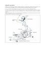
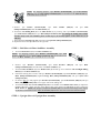
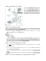
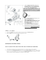
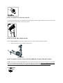
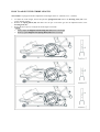
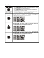
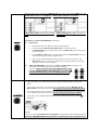
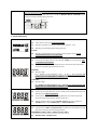
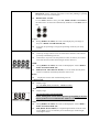
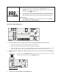
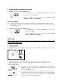
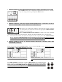
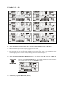
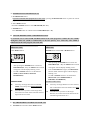
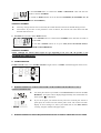
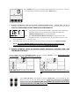
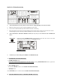
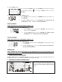
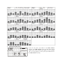
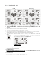
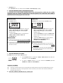
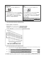
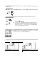
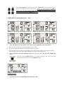
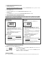
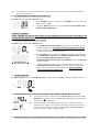
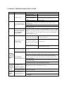
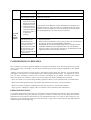
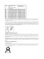
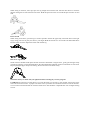
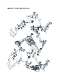
USER MANUAL – EN
IN 6447 Climber For Home Use inSPORTline SM-3276
Product May Vary Slightly From Picture
MADE IN TAIWAN
CONTENTS
SAFETY INSTRUCTION ...................................................................................................................................... 3
ASSEMBLY PARTS .............................................................................................................................................. 4
HARDWARE IDENTIFICATION CHART .......................................................................................................... 5
ASSEMBLE INSTRUCTIONS .............................................................................................................................. 8
OPERATION INSTRUCTIONS .......................................................................................................................... 13
HOW TO ADJUST THE ADJUSTING ENDCAPS OF THE REAR STABILIZER ...................................... 13
HOW TO ADJUST CONSOLE ANGLE ......................................................................................................... 14
HOW TO TOW THE ITEM SAFELY ............................................................................................................. 14
HOW TO ADJUST THE STAND ON THE MIDDLE OF MAIN FRAME’S BASE ..................................... 14
HOW TO ADJUST THE STRIDE LENGTH .................................................................................................. 15
CONSOLE INSTRUCTIONS .............................................................................................................................. 16
Program List ...................................................................................................................................................... 16
Console Buttons ................................................................................................................................................ 17
Console Functions ............................................................................................................................................. 19
MANUAL PROGRAM (P1)............................................................................................................................. 21
PROGRAM (P2 ~ P7) ....................................................................................................................................... 25
BODY FAT PROGRAM (P8) .......................................................................................................................... 29
H. R. C. PROGRAM (P9 ~ P12)....................................................................................................................... 33
USER SETTING PROGRAM (P13 ~ P16) ...................................................................................................... 37
CONSOLE TROUBLE SHOOTING GUIDE ...................................................................................................... 41
CONDITIONING GUIDELINES ......................................................................................................................... 42
PRODUCT PARTS DRAWING (A) .................................................................................................................... 45
PRODUCT PARTS DRAWING (B) .................................................................................................................... 46
PARTS LIST ......................................................................................................................................................... 47
TERMS AND CONDITIONS OF WARRANTY, WARRANTY CLAIMS ....................................................... 51
Exercise can present a health risk. Consult a physician before beginning any exercise program with this
equipment.
If you feel faint or dizzy, immediately discontinue use of this equipment. Serious bodily injury can occur if this
equipment is not assembled and used correctly. Serious bodily injury can also occur if all instructions are not
followed.
Keep children and pets away from equipment when in use. Always make sure all bolts and nuts are tightened
prior to each use. Follow all safety instructions in this manual.
CAUTION: WEIGHT ON THIS PRODUCT SHOULD NOT EXCEED 136KG / 300LBS.
SAFETY INSTRUCTION
WARNING: To reduce the risk of serious injury, read the following safety instructions before using the
Climber.
1. Read all warnings posted on the equipment
2. Read this Owner's Manual and follow it carefully before using the equipment. Make sure that it is
properly assembled and tightened before use
3. We recommend that two people be available for assembly of this product
4. Keep children and pets away from the equipment. Do not allow children and pets to use or play on the
equipment. Always keep children and pets away from the equipment when it is in use
5. It is recommended that you place this exercise equipment on an equipment mat
6. Set up and operate the equipment on a solid level surface. Do not position the equipment on loose rugs
or uneven surfaces
7. Inspect the equipment for worn or loose components prior to each use
8. Tighten / replace any loose or worn components prior to using the equipment
9. Consult a physician prior to commencing an exercise program. If, at any time during exercise, you feel
faint, dizzy, or experience pain, stop and consult your physician
10. Follow your physician's recommendations in developing your own personal fitness program
11. Always choose the workout which best fits your physical strength and flexibility level. Know your
limits and train within them. Always use common sense when exercising
12. Before using this product, please consult your personal physician for a complete physical examination.
13. Do not wear loose or dangling clothing while using the equipment
14. Never exercise in bare feet or socks; always wear correct footwear, such as running, walking, or crosstraining shoes
15. Be careful to maintain your balance while using, mounting, dismounting, or assembling the equipment
loss of balance may result in a fall and serious bodily injury
16. Keep both feet firmly and securely on the Foot Pedals while exercising
17. The equipment should not be used by persons weighing over 300 pounds /136 kgs
18. The equipment should be used by only one person at a time
19. The equipment is for semi-commercial, light-commercial and home usage
20. Maintenance: Replace the defective components immediately and / or keep the equipment out of use
until repair the equipment completely.
21. Make sure that adequate space is available for access to and passage around the equipment; keep at least
a distance of 1 meter from any obstruction object while using the machine
WARNING: Before starting any exercise or conditioning program you should consult with your personal
physician to see if you require a complete physical exam. This is especially important if you are over the age of
35, have never exercised before, are pregnant, or suffer from any illness
READ AND FOLLOW THE SAFETY PRECAUTIONS. FAILURE TO FOLLOW THESE
INSTRUCTIONS CAN RESULT IN SERIOUS BODILY INJURY
ASSEMBLY PARTS
Unpack the box in a clear area. Follow the List of Assembly Parts below to check and make sure all assembly
parts are present and in good condition. Do not dispose of the packing material until the assembly process is
completed. Assembly tools and hardware kit have included for you to use when assembling the product.
Console Upper
Cover
Console Bottom
Cover
Console Sleeve
Upright Post Assembly
Fixed Handlebar
Upper Handlebar
Pedal
Sliding Rail
Upright &
Handlebar Sleeve
Nut & Leveler
Front & Rear
Stabilizer
Main Frame Assembly
Linkage Plug
Rail Sleeve
Securing Cap
Pedal Support Arm
Handrail Base Cover
Pedal Bottom Case
Adaptor
HARDWARE IDENTIFICATION CHART
Unpack the box in a clear area. Follow the List of Hardware Kit below. This chart is provided to help identify
the hardware used in the assembly process. Place the washers, the end of bolts, or screws on the circles to check
for the correct diameter. Use the small scale to check the length of the bolts and screws. Do not dispose of the
packing material until the assembly process is completed
NOTICE: The length of all bolts and screws except those with flat heads is measured from below the head to
the end of the bolt or screw. Flat head bolts and screws are measured from the top of the head to the end of the
bolt or screw
After unpacking the unit, you will notice that the package includes 3 bags of hardware (HARDWARE KIT
A, HARDWARE KIT B and HARDWARE KIT C).
Assembly’s Step 1, 2, 3, 7, 8: Using HARDWARE KIT A
Assembly’s Step 9, 10, 11: Using HARDWARE KIT B
Note:
a.
Please review below to know the content of each hardware kit (A and B)
b. Some small parts may have been pre-attached for shipping. If a part is not in the hardware bag, check to
see if it has been pre-assembled
HARDWARE KIT A
HARDWARE KIT B
Part No. and Description
Q’TY
79 Lock Washer (M8)
6 pcs
80 Washer (8x16x2.0t)
2 pcs
93 Bolt (M6xp1.0x25mm)
2 pcs
94 Bolt (M8xp1.25x16mm)
4 pcs
101 Bolt (M8xp1.25x90mm)
2 pcs
106 Bolt (M8xp1.25x90mm)
2 pcs
109 Carriage Bolt (M8xp1.25x90mm)
2 pcs
112 Nylon Nut (M8xp1.25)
4 pcs
131 Self-Tapping Screw, Flat Head
(M4x10mm)
6 pcs
Part No. and Description
Q’TY
79 Lock Washer (M8)
1 pcs
80 Washer (8x16x2.0t)
1 pcs
88 Self-Tapping Screw, Flat Head (M4x16mm)
4 pcs
90 Bolt (M5xp0.8x25mm)
4 pcs
91 Bolt (M5xp0.8x15mm)
4 pcs
98 Bolt (M6xp1.0x15mm)
4 pcs
99 Bolt (M6xp1.0x35mm)
4 pcs
100 Bolt (M8xp1.25x45mm)
1 pcs
110 Nylon Nut (M6xp1.0)
4 pcs
BEFORE YOU BEGIN
Thank you for choosing the Climber. We take great pride in producing this quality product and hope it will
provide many hours of quality exercise to make you feel better, look better and enjoy life to its fullest.
Yes, it's a proven fact that a regular exercise program can improve your physical and mental health.
Too often, our busy lifestyles limit our time and opportunity to exercise. The equipment provides a convenient
and simple method to begin your assault on getting your body in shape and achieving a happier and healthier
lifestyle.
Before reading further, please review the drawing below and familiarize yourself with the parts that are labeled.
Read this manual carefully before using the equipment.
THE FOLLOWING TOOLS ARE INCLUDED FOR ASSEMBLY:
PHILLIPS
ALLEN WRENCH
WRENCH
SCREWDRIVER (6mm)
(5 mm)
(10 & 13 mm)
ASSEMBLE INSTRUCTIONS
STEP 1 – Front Stabilizer Assembly
a.
Attach the Front Stabilizer (2) to the Main Frame (1).
NOTE: “Small Tip: Attach screws and bolts to the assembly parts first before secure”
To assemble the Front Stabilizer (2) to the Maine Frame (1) with more efficient and easy way, it is
suggested to attach two Washers (8x16x2.0t)(80), two Lock Washers (M8)(79) and two Bolts
(M8xp1.25x90mm)(101) to the Front Stabilizer (2) and the Maine Frame (1) first before fully secure.
**Please do not secure the bolts unless you make sure Bolts all go into screw holes of Front
Stabilizer and Main Frame**
b. Fully secure two Washers (8x16x2.0t)(80), two Lock Washers (M8)(79) and two Bolts
(M8xp1.25x90mm)(101) that attach to the Front Stabilizer (2) to the Main Frame (1).
STEP 2 – Sliding Rail Assembly
NOTE: For shipping purpose, 1pcs Washer (8x16x2.0t)(80), 1pcs Lock Washer
(M8)(79) and 1pcs Bolt (M8xp1.25x20mm)(103) are attached on the Main Frame (1)
as the draft shown on the left.
a. Remove 1pcs Washer (8x16x2.0t)(80), 1pcs Lock Washer (M8)(79) and 1pcs Bolt
(M8xp1.25x20mm)(103) from the Main Frame (1).
b. Attach the Left Sliding Rail (4) to the Main Frame (1) by securing with 1pcs Washer (8x16x2.0t)(80),
1pcs Lock Washer (M8)(79) and 1pcs Bolt (M8xp1.25x20mm)(103). For letting the sliding rail assembly
attaches nicely to the rear stabilizer, please on this step b., do not fully tighten washer and bolts (79, 80
and 103).
c. Then attach the Securing Cap (30) and secure with 1pcs Bolt (M6xp1.0x25mm)(93).
d. Repeat the above same procedure for the right side.
STEP 3 – Rail Sleeve & Rear Stabilizer Assembly
a. Attach the Rail Sleeve (31) to the Rear Stabilizer (3).
NOTE: For shipping purpose, 2pcs Washers (8x16x2.0t)(80), 2pcs Lock
Washers (M8)(79) and 2pcs Bolts (M8xp1.25x20mm)(103) are attached to the
back of the Rear Stabilizer (3) as the draft shown on the right.
b.
c.
d.
e.
f.
Remove 2pcs Washers (8x16x2.0t)(80), 2pcs Lock Washers (M8)(79) and 2pcs Bolts
(M8xp1.25x20mm)(103) from the back of the Rear Stabilizer (3).
Attach the Rear Stabilizer (3) to the Main Frame (1) and then go on to attach the Left and Right Sliding
Rail (4,5) to the Rear Stabilizer (3).
Follow the drawing line to secure with 2pcs Washers (8x16x2.0t)(80), 2pcs Lock Washers (M8)(79), 2pcs
Bolts (M8xp1.25x20mm)(103), 2pcs Carriage Bolt (M8xp1.25x90mm)(109) and 2pcs Nylon Nuts
(M8xp1.25)(112).
Go back to Step 2 to fully tighten 2pcs Washers (8x16x2.0t)(80), 2pcs Lock Washers (M8)(79) and 2pcs
Bolts (M8xp1.25x20mm)(103) on two upper sides of the sliding rail.
Attach the Leveler (23) and Nut (M8xp1.25)(114) to the middle of the Main Frame’s base (1). Adjust the
Leveler (23) until it meets the base of the Main Frame. Then tighten the Nut (114) securely against the
Main Frame (1). NOTE: The purpose of adjust the Leveler (23) is to level the item and get more support
for the base on the Main Frame. Adjust the Leveler (23) until the item sets on the floor without rocking
STEP 4 – Upright Sleeve & Upright Post Assembly
a.
Slide the Upright Sleeve (37) onto the Upright
Post (6).
NOTE: For shipping purpose, 5pcs Nylon Nuts
(M8xp1.25)(112) are attached on the Main Frame
(1).
b.
c.
Remove 5pcs Nylon Nuts (M8xp1.25)(112) from
the Main Frame (1).
Refer to FIG.A’s 3 following drawings, in order
to let point A (Middle Handlebar) and point B
(Pedal Arm Connector) could connect nicely,
before attaching the Upright Post (6) to the Main
Frame (1), make sure raising point A (Middle
Handlebar) in 45 degree, then attach the Upright
Post (6) to the Main Frame (1) and secure with
5pcs Nylon Nuts (M8xp1.25)(112). **Please
don’t fully tighten nuts (112), wait until Step 6
to fully tighten the nuts.**
STEP 5 – Connection Wire Assembly
Connect the Middle Connection Wire (118) to the Lower Connection Wire (119). NOTE: Be careful not to
pinch the wires.
STEP 6 – Linkage & Linkage Plug Assembly
NOTE: For shipping purpose, 1pcs Bolt (M8xp1.25x50mm)(104), 1pcs
Nylon Nut (M8xp1.25)(112) and 1pcs Bolt (M5xp0.8x25mm)(92) are
attached to the Pedal Arm Connector (16) as the draft shown on the right.
a. Remove 1pcs Bolt (M8xp1.25x50mm)(104), 1pcs Nylon Nut (M8xp1.25)(112) and 1pcs Bolt
(M5xp0.8x25mm)(92) from the Pedal Arm Connector (16).
b. Follow the FIG 1 to attach the Right Linkage (15) to the Right Pedal Arm Connector (16) by securing
with 1pcs Bolt (M8xp1.25x50mm)(104), 1pcs Nylon Nut (M8xp1.25)(112). NOTE: In order to let the
Linkage (15) rotate smoothly, after fully tighten the Bolts (104) and Nuts (112), please loose the Nuts
(112) just 1/8 counterclockwise turn.
c. Attach the Right Linkage Plug (58) to the Right Pedal Arm Connector (16) and secure with 1pcs Bolt
(M5xp0.8x25mm)(92).
d. Repeat the above same procedure for the left side.
e. Go back to Step 4 to fully tighten 5pcs Nylon Nuts (M8xp1.25)(112) on the bottom of the Upright Post (6).
f. Slide the Upright Sleeve (37) down to cover the open area of the Main Frame (1).
STEP 7 – Pedal Support Arm Assembly
a.
b.
Refer to the inset drawing FIG .2, cut off the tie
(A) on the front end of the Right Pedal Support
Arm (14). NOTE: Please be sure that the Shaft
Sleeve (68) inside the Pedal Support Arm (14)
does not fall off while cutting off the tie.
Attach the front end of the Right Pedal Support
Arm Assembly (14) to the Right Pivoting Arm
(12) with 1pcs Bolt (M8xp1.25x90mm)(106) and
1pcs Nut (M8xp1.25)(112) NOTE: Please be
sure that Bolt (106) would screw through the
Shaft Sleeve (68) inside front end of the Right
Pedal Support Arm Assembly (14) during
assembly.
NOTE: Refer to the inset drawing FIG.3, for
shipping purpose, 1pcs Roller Spacer (56), 1pcs Bolt
(M8xp1.25x65mm)(105),
1pcs
Nylon
Nut
(M8xp1.25)(112) are attached to the Right Roller
Bracket (69) as the draft shown on the left.
c. Remove 1pcs Roller Spacer (56), 1pcs Bolt
(M8xp1.25x65mm)(105), 1pcs Nylon Nut
(M8xp1.25)(112) from the Right Roller Bracket
(69).
d. Refer to FIG 3. Place the roller under the Right
Pedal Support Arm (14) onto the Right Sliding
Rail (5).
e. Then place the Roller Spacer (56) under the
Right Sliding Rail (5), secure 1pcs Bolt
(M8xp1.25x65mm)(105) through the Roller
Spacer
(56)
with
1pcs
Nylon
Nut
(M8xp1.25)(112).
NOTE: Please be sure not to over-tighten Bolt (105) and Nut (112), after tightening, make sure
the Roller Spacer (56) could still rotate nicely by using finger to rotate the Roller Spacer (56).
If the Roller Spacer (56) is unable to rotate, would cause the roller couldn’t slide smoothly on
the Sliding Rail.
f. Repeat the above same procedure for the left side.
STEP 8 – Pedal Assembly
a.
b.
c.
Attach the Pedal Bottom Case(130) to the Right Pedal (54) and secure with 3pcs Self-Tapping Screw,
Flat Head (M4x10mm) (131).
Attach the Right Pedal (54) to the upper Pedal Plate located on the rear of the Right Pedal Support Arm
(14) and secure with 2pcs Lock Washers (M8)(79) and 2 pcs Bolts (M8xp1.25x16mm)(94).
Repeat the above same procedure for the left side.
STEP 9 – Handrail Base Cover Assembly
To assemble the Handrail Base Cover (42, 43),
place the Left Handrail Base Cover (128) at the
inner side of the Right Middle Handlebar (11).
Place the Right Handrail Base Cover (129) at the
outer side of the Right Middle Handlebar (11).
Bolt the Handrail Base Cover (128, 129) with 2pcs
Self-Tapping Screws, Flat Head (M4x16mm)(88).
Repeat the above assembly process on the left side.
STEP 10 – Fixed Handlebar Assembly
NOTE: 4pcs Washers (8x16x2.0t)(80), 4pcs Lock Washers (M8)(79) and 4pcs Bolts (M8xp1.25x16mm)(102)
will already be attached on two sides of the Fixed Handlebar (7).
a.
Remove
4pcs
Washers
(8x16x2.0t)(80),
4pcs
Lock
Washers
(M8)(79)
and
4pcs
Bolts
(M8xp1.25x16mm)(102) from the Fixed Handlebar (7).
b.
Position the Fixed Handlebar (7) in place through the Upright Post Assembly (6) and secure with 5pcs
Washers (8x16x2.0t)(80), 5pcs Lock Washers (M8)(79) and 4pcs Bolts (M8xp1.25x16mm)(102)and 1pcs
Bolt (M8xp1.25x45mm)(100) NOTE: 1pcs Washer (8x16x2.0t)(80), 1pcs Lock Washer (M8)(79), 1pcs
Bolt (M8xp1.25x45mm)(100) will be packed into HARDWARE KIT B.
STEP 11 – Console and Connection Wire Assembly
a.
Follow FIG.4 to attach the Console Bottom Cover (33) to the Console (32) and secure with 4pcs Bolts
(M5xp0.8x25mm)(90).
b.
Place and secure the Console Assembly (32, 33) onto the iron plate of the Upright Post Assembly (6)
using 4pcs Bolts (M6xp1.0x15mm)(98).
c.
Connect the Front Connection Wire (117) to the Middle Connection Wire (118). Be care not to pinch
d.
the wires
Connect the Front Pulse Sensor Wire (124) to the Rear Pulse Sensor Wire (125). Be care not to pinch
the wires
STEP 12 – Console Sleeve, Handlebar Sleeve & Upper Handlebar Assembly
a.
Attach the Right Console Sleeve (35) and the
Left Console Sleeve (34) to the Upright Post
Assembly (6). Bolt the Console Sleeve (34, 35)
with 4pcs Bolts (M5xp0.8x15mm)(91).
NOTE: Make sure that the Right Console Sleeve (35)
and the Left Console Sleeve (34) would cover the
Upright Cover and the lowest layer of the Console
Bottom Cover (33) as the following illustration
shown.
b.
e.
Slide the Right Handlebar Sleeve (44) onto the
Right Upper Handlebar (9).
Attach the Right Upper Handlebar (9) onto the
Right Middle Handlebar (11) and secure with 2
Bolts (M6xp1.0x35mm)(99) and 2pcs Nylon
Nuts (M6xp1.0)(110).
Slide the Right Handlebar Sleeve (44) down
until it touches the middle part of Handlebar.
Repeat the above same procedure for the left side.
f.
Finish the assembly, make sure that all parts are
c.
d.
tightened before you use the equipment.
STEP 13 – AC Adaptor
a.
b.
Connect the Adaptor to the connector located on the front side of the Main Frame (1).
Plug the Adaptor into an electrical outlet to light up the console.
OPERATION INSTRUCTIONS
HOW TO ADJUST THE ADJUSTING ENDCAPS OF THE REAR STABILIZER
a.
After placing the equipment in the intended location for use, check the stability of the equipment
b.
If it’s the one of the Adjusting EndCaps (27) on rear end of the Rear Stabilizer (3) causes a slight rocking
motion. To level the equipment, turn one or both of the Adjusting EndCaps (27) in clockwise or counterclockwise direction until the equipment sets on the floor without rocking.
HOW TO ADJUST CONSOLE ANGLE
To get the best console angle, it’s suggested to use both hands to hold the upper and lower end of the console and
gently adjust the console angle to the proper position.
HOW TO TOW THE ITEM SAFELY
Hold the Rear Stabilizer (3) up with two hands and tow the item to the desired place carefully
•
Make sure the floor is level while towing the item
HOW TO ADJUST THE STAND ON THE MIDDLE OF MAIN FRAME’S BASE
NOTE: The purpose of adjust the Leveler (23) is to level the item and get more support for the base on the Main
Frame. After finishing all assembly process, place the item on a flat surface. Adjust the Leveler (23) until the
item sets on the floor without rocking, then tighten the Nut (114) securely against the Main Frame (1).
HOW TO ADJUST THE STRIDE LENGTH
The Climber is equipped with three adjustable stride lengths from 19’’ (483mm) to 21’’ (539mm)
a.
b.
c.
To adjust the stride length, loosen and pull the Spring Knob (48). Move the Pivoting Arm (12) to the
proper desired position
Release the Spring Knob (48) and make sure the pin on the knob get into the adjustment hole in the
Pivoting Arm (12).
Repeat the above process to adjust the stride length on left side
NOTE:
1. Always adjust the Right & Left Pivoting Arm (12) in the same height.
2. Securely tighten Right & Left Spring Knob (48) before exercising
CONSOLE INSTRUCTIONS
Take a few minutes to review the console layout. Below
is an overview of the console’s features and functions
We recommend that you use the console to help vary
your workout routine and keep you focused on your
process toward your fitness goals. The console can
become an important source of motivation and interest
which will help keep you on track
Power ON
a.
Make sure the item’s adaptor is correctly plugged into the socket
b. Pedaling or pressing any keys to active the console. The console display will then light up with a short
beep sound, indicating the console will be ready for use
Power Off
The console would automatically shut off after 4 minutes of inactivity
Program List
P1 MANUAL
PROGRAM
P2 ROLLING
PROGRAM
P3 VALLEY
PROGRAM
P4 FAT BURN
PROGRAM
P5 RAMP PROGRAM
P6 FITNESS TEST
PROGRAM
P7 RANDOM
PROGRAM
P8 BODY FAT
PROGRAM
P9 TARGET H.R.
PROGRAM
P10 60% H.R.C.
PROGRAM
P11 75% H.R.C.
PROGRAM
P12 85% H.R.C.
PROGRAM
P13 USER 1 MODE
PROGRAM
P14 USER 2 MODE
PROGRAM
P15 USER 3 MODE
PROGRAM
P16 USER 4 MODE
PROGRAM
Console Buttons
a.
Press START/PAUSE to begin your exercise
b.
Press START/PAUSE again to stop and pause all functions during your exercise
program. All the date on the display will then freeze.
c.
Press START/PAUSE again to resume the program and all the date displayed
will continue until the program has finished.
d.
HOLD TO RESET function: Continue pressing START/PAUSE, all the date
will return to 0 and the console will return to POWER ON status
Press ENTER to confirm the program function (PROGRAM, TIME, HEIGHT,
WEIGHT, DISTANCE, CALORIES, AGE, GENDER, TARGET H.R. and
TORQUE/RESISTANCE LEVEL in each time interval)
Press UP to increase the values of the program function (PROGRAM, TIME,
HEIGHT, WEIGHT, DISTANCE, CALORIES, AGE, GENDER, TARGET H.R.
and TORQUE/RESISTANCE LEVEL in each time interval)
Press DOWN to decrease the values of the program function (PROGRAM, TIME,
HEIGHT, WEIGHT, DISTANCE, CALORIES, AGE, GENDER, TARGET H.R.
and TORQUE/RESISTANCE LEVEL in each time interval)
During workout (after pressing START/PAUSE), the user could press MODE to select
SPEED, DISTANCE and CALORIES, or RPM, ODO (Odometer) and WATT
RPM, ODO, WATT will show at the same
time
SPEED, DISTANCE, CAL. will show at
the same time
DISTANCE and ODO (ODOMETER) information:
DISTANCE:
a.
This measures the total distance from 0 to 999 km/Mile.
b.
After pressing START/PAUSE, DISTANCE will count up. Press
START/PAUSE again to pause all functions and DISTANCE value during your
exercise program.
c.
Press START/PAUSE again to resume the program and DISTANCE value will
continue counting up until the program finish
d.
The console would automatically shut off after 4 minutes of inactivity. The
DISTANCE value’s counting will restart from zero after pedaling or pressing
any keys to active the console again
ODO (ODOMETER): The function of ODO and DISTANCE are similar will
accumulate the total distance traveled by the item during
workout. If there is any necessary to reset ODO’s distance value,
press UP, MODE, DOWN and ENTER at the same time to let
the motor automatically calibrate to reset ODO value to zero
a.
PULSE RECOVERY button measures how quickly you return to a resting hear rate
after exercising. You could use this button to measure improvement as you get into
shape
b.
The console will monitor your pulse for 60 seconds and calculate a HEART RATE
RECOVERY value from F1.0 to F6.0. F1.0 is best; F6.0 is worst (For Reference Only)
c.
The readout should only be used as a comparison between workouts. It’s recommended
to use right after any aerobic exercise. Stop exercising before starting the function.
d.
Your pulse will be displayed approximately few seconds after the heart symbol “
displayed
” is
NOTE:
If you don’t hold the HEART RATE SENSORS on the handrails with both hands properly,
the console’s HEART RATE value would show “0” and the main screen would show “F6.0”
after the console counts down to zero, which means the HEART RATE SENSORS won’t be
able to pick up the signals. Press any keys to stop the long beep sound, then press PULSE
RECOVERY button again and make sure to hold the HEART RATE SENSORS on the
handrails with both hands properly this time.
Console Functions
PROGRAM:
The console comes with 16 preset programs
Displays programs for selection during setup, from P1 ~ P16
Displays the selected program during exercise
LEVEL:
Displays torque/resistance level of the current program, from 1 to 16
torque/resistance level; 1 level increment
TIME:
Count Up: If a target time was not selected, TIME will count up from 0:00
to maximum 99:59 minutes
Count Down: If you have set the target time, the console will count down
from that selected target time down to 0:00
HEIGHT:
Display range:
110 ~ 250cm; 0.5 cm increment / 3’08’’ ~ 8’ 00’’; 1 inch increment; the
product is not recommended for children’s use
WEIGHT:
Display range:
10 ~ 200KG; 0.2 KG increment / 23 ~ 440 LBS; 0.5 LBS increment; the
product is not recommended for children’s use
DISTANCE:
Count Up: If a target distance was not selected, this would measure the total
distance from 0:00 to 999 km/mile
Count Down: If you have set the target distance, the console will count
down from that selected target distance down to 0
During workout (after pressing START/PAUSE), the user could press
MODE button to select DISTANCE, or ODO (Odometer)
ODO:
The function of ODO and DISTANCE are similar will accumulate the total
distance traveled by the item during workout
DIFFERENT RESET INFO. of DISTANCE & ODO:
RESET INFO. of DISTANCE:
The console would automatically shut off after 4 minutes of inactivity. The
DISTANCE value’s counting will restart to zero after pedaling or pressing
any keys to active the console again
RESET INFO. of ODO:
To reset ODO’s distance value, press UP, MODE, DOWN and ENTER at
the same time to let the motor automatically calibrate to reset ODO value to
zero
FAT%:
During BODY FAT TEST, the result would display the percentage of
body fat in BODY FAT PROGRAM (P8)
Your body fat percentage is simply the percentage of the fat your body
contains
CALORIES:
Count Up: If target calories were not selected, this measures total calories
your body burned during exercise
Count Down: If you have set the preference value of calories, the console
will count down from that selected target calories down to 0
BMR:
During BODY FAT TEST, the result would display the value of BMR in
BODY FAT PROGRAM (P8)
BMR (BASAL METABOLIC RATE) is a rate at which the body burns
calories to maintain normal body functions while at rest
WATT:
Display the current value of Watt during exercise
TARGET H.R.:
Display range:
60 ~ 220 BPM (beats per minute) ; 1 BPM increment
AGE:
Display range:
10 ~ 99 years old; 1 year-old increment
NOTE: Although the console allows input for age beginning at 10 years
old, the product is not recommended for children’s use
BMI:
During BODY FAT TEST, the result would display the value of BMI in
BODY FAT PROGRAM (P8)
BMI (BODY MASS INDEX) is a height/weight formula. From the value
of your BMI, you can see whether you are underweight, normal weight,
overweight or obese
HEART RATE:
You must place both of your hands on the Pulse Sensors on the
Handlebar. Your pulse will be displayed approximately few seconds after
the heart symbol “
” is displayed
If you do not place your hands correctly and a few seconds passes without a
pulse input, the console will turn off the pulse circuit. Place your hands
back on the Pulse Sensors correctly, the pulse readout will appear again
BODY TYPE:
During BODY FAT TEST, the result would display the value of BODY
TYPE in BODY FAT PROGRAM (P8)
MANUAL PROGRAM (P1)
1.
2.
Prior information: Press any button on the console or begin pedaling to turn on the console
a.
Make sure that the power cord is properly plugged into the socket.
b.
The console would automatically shut off after 4 minutes of inactivity
c.
Press any button on the console or begin pedaling to turn on the console. After a few seconds, the
console will then light up with a short beep sound, indicating the console will be ready for use
Prior information: ”HOLD TO RESET” button, an easy way to reset and enter into POWER ON
status
Continue pressing START/PAUSE a few seconds, all the date will reset to the initial
value and the console will return to POWER ON status
POWER ON status
3.
Normal way to operate MANUAL PROGRAM (P1)
A. ENTER MANUAL PROGRAM (P1)
ENTER button:
a. START/PAUSE button:
If you have selected other program (P2~P16),
pressing START/PAUSE button to pause the
current program
When the power is turned on, the manual program
(P1) will be selected, pressing ENTER button to
confirm and enter MANUAL PROGRAM (P1)
b. UP or DOWN button:
Press UP or DOWN button to select MANUAL
PROGRAM (P1)
c. ENTER button:
Press ENTER button to confirm and enter
MANUAL PROGRAM (P1)
B. SET THE DESIRED TIME or DESIRED DISTANCE
To avoid the user to select TIME and DISTANCE in the same program to confuse the user couldn’t
distinguish which one (TIME or DISTANCE) as the first priority. User could only select TIME or
DISTANCE in the same program, one at the time
If you would like to select TIME value, not
DISTANCE value:
If you would like to select DISTANCE value, not
TIME value:
UP or DOWN button:
ENTER button and then UP or DOWN button:
a.
b.
After pressing the ENTER button to enter into
a.
After pressing the ENTER button to enter into
MANUAL PROGRAM (P1), the TIME function
MANUAL PROGRAM (P1), the TIME
mode will appear with the display flashing “0:00”.
function mode will appear with the display
Use UP or DOWN buttons to set the desired
flashing “0:00”.
TIME (1:00 TO 99:00; 1 MINUTE
b.
INCREMENT)
function mode will then appear with the display
NOTE for TIME:
Count Up: If a target time was not selected,
TIME will count up from 0:00 to maximum
99:59 minutes
Count Down: If you have set the target time, the
console will count down from that selected
target time down to 0:00
Press the ENTER button again, the DISTANCE
flashing “0.0”
c.
Use UP or DOWN buttons to set the desired
DISTANCE (1 TO 999KM/MILE; 1
KM/MILE
INCREMENT)
NOTE for DISTANCE:
Count Up: If a target distance was not selected,
this would measure the total distance from
0:00 to 999 km/mile
Count Down: If you have set the target
distance, the console will count down from
the selected target time down to 0
C. SET THE DESIRED CALORIES and YOUR AGE
1.
ENTER button and then UP or DOWN button:
a.
Press ENTER button to confirm TIME or DISTANCE value and enter
the mode to set the CALORIES
b. Use UP or DOWN buttons to set the desired CALORIES (10 TO
9990KCAL; 10 KCAL INCREMENT)
NOTE for CALORIES:
Count Up: If target calories was not selected, this would measure total calories burned during exercise
Count Down: If you have set the preference value of calories, the console will count down from that
selected value down to 0
2.
ENTER button and then UP or DOWN button:
a. Press ENTER button to confirm the CALORIES value and enter the
mode to set the AGE
b. Use UP or DOWN buttons to set your AGE (10 TO 99 YEARS
OLD; 1 YEAR OLD INCREMENT)
NOTE for AGE:
NOTE: Although the console allows input for ages beginning at 10 years old, the product is not
recommended for children’s use
D. START EXERCISE
START/ PAUSE button: Press START/ PAUSE to begin exercise. “START” would then appear on the screen
E. DURING WORKOUT, ALWAYS MONITOR YOUR CURRENT HEART RATE STATUS”
NOTE for HEART RATE:
You must place both of your hands on the Pulse Sensors located on the Seat
Handlebar. Your pulse will be displayed approximately few seconds after the
heart symbol “
” is displayed
If you do not place your hands correctly and a few seconds pass without a
pulse input, the console will turn off the pulse circuit. The console will then
display an error message “P”. Place your hands back on the Pulse Sensors
correctly, the pulse readout will appear again
F. DURING WORKOUT, THE TORQUE/TENSION LEVEL IS EASILY CHANGED AT ANY TIME
UP or DOWN button: You can change the torque/tension level (from 1 to 16 levels)
at any time during workout by pressing UP or DOWN button
G. DURING WORKOUT, ALWAYS NOTICE TARGET HEART RATE – A EASY WAY TO SET A
GOAL TO “STRENGTHEN YOUR CARDIOVASCULAR WORKOUT
To improve your cardiovascular condition, while input your personal age during
the setting mode, the console will calculate the appropriate TARGET HEART
RATE for you automatically
The TARGET HEART RATE calculation is based on 85% of the maximum
heart rate. For example: For a 30-year-old user, the max. user heart rate should be 161 = (220-30) x 85%
The console will monitor your pulse and compare the value of your pulse with TARGET HEART
RATE. The value of HEART RATE will keep flashing to warn you to slow down or lower the
torque/resistance level if your pulse value is greater than TARGET HEART RATE
H. DURING WORKOUT, HOW TO REVIEW SPEED, DISTANCE, CALORIES, RPM, ODO
(ODOMETER) AND WATT
During workout (after pressing START/PAUSE), the user could press MODE to select SPEED, DISTANCE
and CALORIES, or RPM, ODO (Odometer) and WATT
RPM, ODO, WATT will show at the same time
SPEED, DISTANCE, CAL. will show at the same
time
About ODO (odometer), the function is similar to DISTANCE, will accumulate the total
distance traveled by the item during workout. If there is any necessary to reset ODO’s
distance value, press UP, MODE, DOWN and ENTER at the same time to let the motor
automatically calibrate to reset ODO value to zero
PROGRAM (P2 ~ P7)
1.
Prior information: Press any button on the console or begin pedaling to turn on the console
a.
Make sure that the power cord is properly plugged into the socket
b.
The console would automatically shut off after 4 minutes of inactivity
c.
Press any button on the console or begin pedaling to turn on the console. After a few seconds, the console
will then light up with a short beep sound, indicating the console will be ready for use
2.
Prior information: ”HOLD TO RESET” button, an easy way to reset and enter into POWER ON
status
Continue pressing START/PAUSE a few seconds, all the date will reset to the initial
value and the console will return to POWER ON status
POWER ON status
3.
Normal way to operate PROGRAM (P2~P7)
A. ENTER MANUAL PROGRAM (P2~P7)
a. START/PAUSE button:
If you have selected other program (P1 or P8 ~ P16), pressing START/PAUSE button to pause the current
program
b. UP or DOWN button:
Press UP or DOWN button to select PROGRAM (P2 ~ P7)
c. ENTER button:
Press ENTER button to confirm and enter PROGRAM (P2 ~ P7)
B. SET THE DESIRED TIME or DESIRED DISTANCE
To avoid the user to select TIME and DISTANCE in the same program to confuse the user couldn’t
distinguish which one (TIME or DISTANCE) as the first priority. User could only select TIME or
DISTANCE in the same program, one at the time
If you would like to select TIME value, not
If you would like to select DISTANCE value, not
DISTANCE value:
TIME value:
UP or DOWN button:
ENTER button and then UP or DOWN button:
a.
a.
After pressing the ENTER button to enter into
PROGRAM (P2 ~ P7), the TIME function mode
PROGRAM (P2 ~ P7), the TIME function mode
will appear with the display flashing “0:00”.
will appear with the display flashing “0:00”
b.
After pressing the ENTER button to enter into
b.
Press the ENTER button again, the DISTANCE
Use UP or DOWN buttons to set the desired
function mode will then appear with the display
TIME (1:00 TO 99:00; 1 MINUTE
flashing “0.0”
INCREMENT)
c.
Use UP or DOWN buttons to set the desired
DISTANCE (1 TO 999KM/MILE; 1
NOTE for TIME:
KM/MILE INCREMENT)
NOTE for DISTANCE:
Count Up: If a target time was not selected,
TIME will count up from 0:00 to maximum
99:59 minutes
Count Down: If you have set the target time,
the console will count down from that selected
target time down to 0:00
C. SET THE DESIRED CALORIES and YOUR AGE
1. ENTER button and then UP or DOWN button:
Count Up: If a target distance was not selected,
this would measure the total distance from 0:00
to 999 km/mile
Count Down: If you have set the target
distance, the console will count down from the
selected target time down to 0
a. Press ENTER button to confirm the TIME or DISTANCE value and enter the
mode to set the CALORIES
b. Use UP or DOWN buttons to set the desired CALORIES (10 TO 9990KCAL; 10
KCAL INCREMENT)
NOTE for CALORIES:
Count Up: If target calories was not selected, this would measure total calories burned during exercise
Count Down: If you have set the preference value of calories, the console will count down from that
selected value down to 0
2. ENTER button and then UP or DOWN button:
a. Press ENTER button to confirm the CALORIES value and enter the mode to
set the AGE
b. Use UP or DOWN buttons to set your AGE (10 TO 99 YEARS OLD; 1
YEAR OLD INCREMENT)
NOTE for CALORIES:
NOTE: Although the console allows input for ages beginning at 10 years old, the product is not
recommended for children’s use
D. START EXERCISE
START/ PAUSE button: Press START/ PAUSE to begin exercise. “START” would then appear on the screen
E. DURING WORKOUT, ALWAYS MONITOR YOUR CURRENT HEART RATE STATUS”
NOTE for HEART RATE
You must place both of your hands on the Pulse Sensors located on the Seat
Handlebar. Your pulse will be displayed approximately few seconds after the
heart symbol “
” is displayed
If you do not place your hands correctly and a few seconds pass without a
pulse input, the console will turn off the pulse circuit. The console will then
display an error message “P”. Place your hands back on the Pulse Sensors
correctly, the pulse readout will appear again
F. DURING WORKOUT, THE TORQUE/TENSION LEVEL IS EASILY CHANGED AT ANY TIME
UP or DOWN button: You can change the torque/tension level (from 1 to 16 levels)
at any time during workout by pressing UP or DOWN button
G. DURING WORKOUT, ALWAYS NOTICE TARGET HEART RATE – A EASY WAY TO SET A
GOAL TO “STRENGTHEN YOUR CARDIOVASCULAR WORKOUT
To improve your cardiovascular condition, while input your personal age
during the setting mode, the console will calculate the appropriate
TARGET HEART RATE for you automatically
The TARGET HEART RATE calculation is based on 85% of the
maximum heart rate. For example: For a 30-year-old user, the max. user
heart rate should be 161 = (220-30) x 85%
The console will monitor your pulse and compare the value of your pulse with TARGET HEART
RATE. The value of HEART RATE will keep flashing to warn you to slow down or lower the
torque/resistance level if your pulse value is greater than TARGET HEART RATE
H. DURING WORKOUT, HOW TO REVIEW SPEED, DISTANCE, CALORIES, RPM, ODO
(ODOMETER) AND WATT
During workout (after pressing START/PAUSE), the user could press MODE to select SPEED, DISTANCE
and CALORIES, or RPM, ODO (Odometer) and WATT
RPM, ODO, WATT will show at the same time
SPEED, DISTANCE, CAL. will show at the same
time
About ODO (odometer), the function is similar to DISTANCE, will accumulate the total
distance traveled by the item during workout. If there is any necessary to reset ODO’s
distance value, press UP, MODE, DOWN and ENTER at the same time to let the motor
automatically calibrate to reset ODO value to zero
BODY FAT PROGRAM (P8)
1.
Prior information: Press any button on the console or begin pedaling to turn on the console
a.
Make sure that the power cord is properly plugged into the socket.
b.
The console would automatically shut off after 4 minutes of inactivity
c.
Press any button on the console or begin pedaling to turn on the console. After a few seconds, the console
will then light up with a short beep sound, indicating the console will be ready for use
2.
Prior information: ”HOLD TO RESET” button, an easy way to reset and enter into POWER ON
status
Continue pressing START/PAUSE a few seconds, all the date will reset to the initial
value and the console will return to POWER ON status
POWER ON status
3.
Normal way to select and operate BODY FAT PROGRAM (P8)
A. ENTER BODY FAT PROGRAM (P8)
a. START/PAUSE button:
If you have selected other program (P1 ~ P7, P9 ~ P16), pressing START/PAUSE button to pause the
current program
b. UP or DOWN button:
Press UP or DOWN button to select BODY FAT PROGRAM (P8)
c. ENTER button:
Press ENTER button to confirm and enter BODY FAT PROGRAM (P8)
B. SET THE PERSONAL INFO. ( GENDER, HEIGHT and AGE )
1. UP or DOWN button:
After pressing the ENTER button, the GENDER function mode will appear
with the display flashing “
”. Use UP or DOWN buttons to set your
GENDER
2. ENTER button and then UP or DOWN button:
a.
Press ENTER button to confirm your GENDER and enter the mode to set
your HEIGHT
b. Use UP or DOWN buttons to set your HEIGHT (110 ~ 250CM; 0.5 CM
INCREMENT / 3’08’’ ~ 8’ 00’’; 1 INCH INCREMENT)
NOTE for HEIGHT:
NOTE: The product is not recommended for children’s use
3. ENTER button and then UP or DOWN button:
a.
Press ENTER button to confirm your HEIGHT value and enter the
mode to set your WEIGHT
b. Use UP or DOWN buttons to set your WEIGHT (10 ~ 200KG; 0.2 KG
INCREMENT / 23 ~ 440 LBS; 0.5 LBS INCREMENT)
NOTE for WEIGHT:
NOTE: The product is not recommended for children’s use
4. ENTER button and then UP or DOWN button:
a.
Press ENTER button to confirm your WEIGHT value and enter the mode
to set the AGE
b. Use UP or DOWN buttons to set your AGE (10 TO 99 YEARS OLD; 1
YEAR OLD INCREMENT)
NOTE for AGE:
NOTE: Although the console allows input for ages beginning at 10 years old, the product is not
recommended for children’s use
C. START TESTING YOUR BODY FAT
START/ PAUSE button: Press START/ PAUSE to start testing your body fat. The testing time takes about 10
seconds, please review the next page to understand the meaning of the result
D. THE BODY FAT RESULT INFORMATION
The illustration on the left is just an example to
show you what the result should look like, each
person has different body fat condition depends
on the user’s current health condition from time
to time
1.
BMI (BODY MASS INDEX):
Body Mass Index is a height / weight formula used by health and weight professionals around the world to
asses a person’s body weight, measuring the level of body fatness in an individual. From your body mass
index number you can see if you are underweight, normal weight, overweight or obese
2.
THE RESULT
THE VALUE OF BMI
Underweight
Under 20 (19 for women)
Normal Weight
Between 20 and 24.99
Overweight
Between 25 and 29.99
Obese 1
Between 30 and 34.99
Obese 2
Between 35 and 39.99
Extreme Obesity
40 and above
BMI conclusion very
slightly according to
gender. Here is a
general summary of
weight-status based on
BMI
BMR (BASAL METABOLIC RATE):
Basal Metabolic Rate is the rate at which the body burns calories to maintain normal body functions while at
rest. BMR is the largest factor in determining overall metabolic rate and how many calories you need to
maintain, lose or gain weight.
To lose weight, you should try to eat fewer calories than your basic calories need. In order to lose weight,
calories should not be your only concern. Exercise is vital, too.
3.
BODY FAT%:
You body fat percentage is simply the percentage of fat your body contains. If you are 150 pounds and 10%
fat, it means that your body consists of 15 pounds fat and 135 pounds lean body mass, such as bone, muscle,
organ tissue, blood and everything else.
4.
BODY TYPE:
Refer to the following list to determine what your body type is:
5.
ERROR INFORMATION:
If you do not place your hands on the Pulse Sensors
correctly, the Pulse Sensors won’t be able pick up the
signals. The console would then display an error message
“E3”. To test it again, be sure to place your hands back on
the Pulse Sensors correctly
H. R. C. PROGRAM (P9 ~ P12)
1.
Prior information: Press any button on the console or begin pedaling to turn on the
console
a.
Make sure that the power cord is properly plugged into the socket
b.
The console would automatically shut off after 4 minutes of inactivity
c.
Press any button on the console or begin pedaling to turn on the console. After a few seconds, the console
will then light up with a short beep sound, indicating the console will be ready for use
2.
Prior information: ”HOLD TO RESET” button, an easy way to reset and enter into POWER ON
status
Continue pressing START/PAUSE a few seconds, all the date will reset to the initial
value and the console will return to POWER ON status
POWER ON status
3.
Normal way to operate H.R.C. PROGRAM (P9~P12)
A. ENTER H.R.C. PROGRAM (P9~P12)
a. START/PAUSE button:
If you have selected other program (P1 ~ P8 or P13 ~ P16), pressing START/PAUSE button to pause the
current program
b. UP or DOWN button:
Press UP or DOWN button to select H.R.C. PROGRAM (P9 ~ P12)
c. ENTER button:
Press ENTER button to confirm and enter H.R.C. PROGRAM (P9 ~ P12)
B. SET THE DESIRED TIME or DESIRED DISTANCE
To avoid the user to select TIME and DISTANCE in the same program to confuse the user couldn’t
distinguish which one (TIME or DISTANCE) as the first priority. User could only select TIME or
DISTANCE in the same program, one at the time
If you would like to select TIME value, not
DISTANCE value:
If you would like to select DISTANCE value, not
TIME value:
UP or DOWN button:
ENTER button and then UP or DOWN button:
a.
After pressing the ENTER button to enter into
H.R.C. PROGRAM (P9 ~ P12), the TIME
function mode will appear with the display
flashing “0:00”
b.
After pressing the ENTER button to enter into
H.R.C. PROGRAM (P9 ~ 12), the TIME
function mode will appear with the display
flashing “0:00”.
b.
Use UP or DOWN buttons to set the desired
TIME (1:00 TO 99:00; 1 MINUTE
INCREMENT)
c.
Press the ENTER button again, the DISTANCE
function mode will then appear with the display
flashing “0.0”
d.
Use UP or DOWN buttons to set the desired
DISTANCE (1 TO 999KM/MILE; 1
KM/MILE INCREMENT)
NOTE for TIME:
Count Up: If a target time was not selected, TIME
will count up from 0:00 to maximum 99:59 minutes
Count Down: If you have set the target time, the
console will count down from that selected target
time down to 0:00
NOTE for DISTANCE:
Count Up: If a target distance was not selected,
this would measure the total distance from 0:00 to
999 km/mile
Count Down: If you have set the target distance,
the console will count down from the selected
target time down to 0
C. SET THE DESIRED CALORIES
ENTER button and then UP or DOWN button:
a.
Press ENTER button to confirm the TIME or DISTANCE value and enter
the mode to set the CALORIES
b. Use UP or DOWN buttons to set the desired CALORIES (10 TO
9990KCAL; 10 KCAL INCREMENT)
NOTE for CALORIES:
Count Up: If target calories was not selected, this would measure total calories burned during exercise
Count Down: If you have set the preference value of calories, the console will count down from that
selected value down to 0
D. SET THE TARGET HEART RATE or YOUR AGE
If you have selected PROGRAM 9, select TARGET
HEART RATE:
If you have selected PROGRAM 10~12, select your
AGE:
ENTER button and then UP or DOWN button:
ENTER button and then UP or DOWN button:
a. Press ENTER button to confirm the CALORIES a. Press ENTER button to confirm the CALORIES
value and enter the mode to set the TARGET H.R.
value and enter the mode to set the AGE
b. Use UP or DOWN buttons to set the desired
TARGET H.R. (60 ~ 220 BPM (BEATS PER
MINUTE) ; 1 BPM INCREMENT)
b. Use UP or DOWN buttons to set your AGE (10 TO
99 YEARS OLD; 1 YEAR OLD INCREMENT)
NOTE for AGE:
NOTE: Although the console allows input for ages
beginning at 10 years old, the product is not
recommended for children’s use
E. MUST-KNOWN HEART RATE PROGRAM INFO.
a. SIMPLE FORMULA OVERVIEW:
BEGINNER: 60% of maximum heart rate; 60% of (220 – you age)
TRAINER: 75% of maximum heart rate; 75% of (220 – you age)
ACTIVE TRAINER: 85% of maximum heart rate; 85% of (220 – you age)
b. CONSOLE MONITOR YOUR CURRENT PULSE
The console will monitor your actual pulse and adjust the resistance/torque level automatically to keep
your pulse within your TARGET HEART RATE ZONE.
If you current pulse > (the value of the TARGET HEART RATE ± 5), the console would decrease
one resistance/torque level automatically
If you current pulse < (the value of the TARGET HEART RATE± 5), the console would increase
one resistance/torque level automatically
For example: if your age is 30, 60% of your max. heart rate is 114. To determine your HEART RATE ZONE,
the minimum number in your zone is 109 (114 – 5) and your maximum number in your zone is 119 (114 5),
so you TARGET HEART RATE ZONE in this example is 109 to 119. The program will monitor your pulse
and adjust the torque/resistance level automatically to keep your pulse within the HEART RATE ZONE (109 –
119) during workout
F. START EXERCISE
START/ PAUSE button: Press START/ PAUSE to begin exercise. “START” would then appear on the screen
G. DURING WORKOUT, ALWAYS MONITOR YOUR CURRENT HEART RATE STATUS
NOTE for HEART RATE:
You must place both of your hands on the Pulse Sensors located on the Seat
Handlebar. Your pulse will be displayed approximately few seconds after the
heart symbol “
” is displayed
If you do not place your hands correctly and a few seconds pass without a
pulse input, the console will turn off the pulse circuit. The console will then
display an error message “P”. Place your hands back on the Pulse Sensors
correctly, the pulse readout will appear again
H. DURING WORKOUT, THE TORQUE/TENSION LEVEL IS EASILY CHANGED AT ANY TIME
UP or DOWN button: You can change the torque/tension level (from 1 to 16 levels) at
any time during workout by pressing UP or DOWN button
I.
DURING WORKOUT, HOW TO REVIEW SPEED, DISTANCE, CALORIES, RPM, ODO
(ODOMETER) AND WATT
During workout (after pressing START/PAUSE), the user could press MODE to select SPEED, DISTANCE
and CALORIES, or RPM, ODO (Odometer) and WATT
RPM, ODO, WATT will show at the same time
SPEED, DISTANCE, CAL. will show at the same
time
About ODO (odometer), the function is similar to DISTANCE, will accumulate the total
distance traveled by the item during workout. If there is any necessary to reset ODO’s
distance value, press UP, MODE, DOWN and ENTER at the same time to let the motor
automatically calibrate to reset ODO value to zero
USER SETTING PROGRAM (P13 ~ P16)
1.
Prior information: Press any button on the console or begin pedaling to turn on the console
a. Make sure that the power cord is properly plugged into the socket
b. The console would automatically shut off after 4 minutes of inactivity
c. Press any button on the console or begin pedaling to turn on the console. After a few seconds, the console
will then light up with a short beep sound, indicating the console will be ready for use
2.
Prior information: ”HOLD TO RESET” button, an easy way to reset and enter into POWER ON
status
Continue pressing START/PAUSE a few seconds, all the date will reset to the initial
value and the console will return to POWER ON status
POWER ON status
3.
Normal way to operate USER MODE PROGRAM (P13~P16)
A. ENTER USER MODE PROGRAM (P13~P16)
a. START/PAUSE button:
If you have selected other program (P1 ~ P12), pressing START/PAUSE button to pause the current
program
b.
UP or DOWN button:
Press UP or DOWN button to select USER MODE PROGRAM (P13 ~ P16)
c. ENTER button:
Press ENTER button to confirm and enter USER MODE PROGRAM (P13 ~ P16)
B. SET THE DESIRED TIME or DESIRED DISTANCE
To avoid the user to select TIME and DISTANCE in the same program to confuse the user couldn’t
distinguish which one (TIME or DISTANCE) as the first priority. User could only select TIME or
DISTANCE in the same program, one at the time
If you would like to select TIME value, not
DISTANCE value:
If you would like to select DISTANCE value, not
TIME value:
UP or DOWN button:
ENTER button and then UP or DOWN button:
a.
After pressing the ENTER button to enter into
USER MODE PROGRAM (P13 ~ P16), the
TIME function mode will appear with the display
flashing “0:00”
a.
After pressing the ENTER button to enter into
USER MODE PROGRAM (P13 ~ P16), the
TIME function mode will appear with the display
flashing “0:00”
b.
Press the ENTER button again, the DISTANCE
function mode will then appear with the display
flashing “0.0”
c.
Use UP or DOWN buttons to set the desired
DISTANCE (1 TO 999KM/MILE; 1
KM/MILE INCREMENT)
b. Use UP or DOWN buttons to set the desired
TIME (1:00 TO 99:00; 1 MINUTE
INCREMENT)
NOTE for TIME:
Count Up: If a target time was not selected,
TIME will count up from 0:00 to maximum
99:59 minutes
NOTE for DISTANCE:
Count Down: If you have set the target time,
the console will count down from that selected
target time down to 0:00
Count Up: If a target distance was not selected,
this would measure the total distance from 0:00
to 999 km/mile
Count Down: If you have set the target
distance, the console will count down from the
selected target time down to 0
C. SET THE DESIRED CALORIES and YOUR AGE
ENTER button and then UP or DOWN button:
a.
Press ENTER button to confirm TIME or DISTANCE value and enter the
mode to set the CALORIES
b. Use UP or DOWN buttons to set the desired CALORIES (10 TO
9990KCAL; 10 KCAL INCREMENT)
NOTE for CALORIES:
Count Up: If target calories was not selected, this would measure total calories burned during exercise
Count Down: If you have set the preference value of calories, the console will count down from that
selected value down to 0
D. SET THE DESIRED CALORIES and YOUR AGE
ENTER button and then UP or DOWN button:
a.
Press ENTER button to confirm the CALORIES value and enter the
mode to set the AGE
b. Use UP or DOWN buttons to set your AGE (10 TO 99 YEARS OLD; 1
YEAR OLD INCREMENT)
NOTE for CALORIES:
NOTE: Although the console allows input for ages beginning at 10 years old, the product is not
recommended for children’s use
E. SET THE TORQUE/RESISTANCE LEVEL
ENTER button and then UP or DOWN button:
a.
The USER SETTING PROGRAM allows the user to manually set the
torque/resistance level, the console will divide the time into 10 intervals.
The user could through their preference to set the desired
torque/resistance level in each time interval
b. Press ENTER button to confirm the AGE value and enter the mode to set
the EACH TIME INTERVAL OF TORQUE/RESISTANCE LEVEL
(1 TO 16 TORQUE/RESISTANCE LEVELS; 1
TORQUE/RESISTANCE LEVEL INCREMENT), then press ENTER
button to confirm
c.
Continue following the above process to finish setting the preference
TORQUE/RESISTANCE LEVEL in 10 time intervals. The program
profile will be storied in the memory after setup. You can modify the
profile anytime under the STOP mode
F. START EXERCISE
START/ PAUSE button: Press START/ PAUSE to begin exercise. “START” would then appear to the screen
G. DURING WORKOUT, ALWAYS MONITOR YOUR CURRENT HEART RATE STATUS
You must place both of your hands on the Pulse Sensors located on the Seat
Handlebar. Your pulse will be displayed approximately few seconds after the
heart symbol “
” is displayed
If you do not place your hands correctly and a few seconds pass without a
pulse input, the console will turn off the pulse circuit. The console will then
display an error message “P”. Place your hands back on the Pulse Sensors
correctly, the pulse readout will appear again
H. DURING WORKOUT, THE TORQUE/TENSION LEVEL IS EASILY CHANGED AT ANY TIME
UP or DOWN button: You can change the torque/tension level (from 1 to 16
levels) at any time during workout by pressing UP or DOWN button
I.
DURING WORKOUT, ALWAYS NOTICE TARGET HEART RATE – A EASY WAY TO SET A
GOAL TO “STRENGTHEN YOUR CARDIOVASCULAR WORKOUT
To improve your cardiovascular condition, while input your personal age
during the setting mode, the console will calculate the appropriate
TARGET HEART RATE for you automatically
The TARGET HEART RATE calculation is based on 85% of the
maximum heart rate. For example: For a 30-year-old user, the max. user
heart rate should be 161 = (220-30) x 85%
The console will monitor your pulse and compare the value of your pulse
with TARGET HEART RATE. The value of HEART RATE will keep
flashing to warn you to slow down or lower the torque/resistance level if
your pulse value is greater than TARGET HEART RATE
J. DURING WORKOUT, HOW TO REVIEW SPEED, DISTANCE, CALORIES, RPM, ODO
(ODOMETER) AND WATT
During workout (after pressing START/PAUSE), the user could press MODE to select SPEED, DISTANCE
and CALORIES, or RPM, ODO (Odometer) and WATT
RPM, ODO, WATT will show at the same time
SPEED, DISTANCE, CAL. will show at the same
time
About ODO (odometer), the function is similar to DISTANCE, will accumulate the total
distance traveled by the item during workout. If there is any necessary to reset ODO’s
distance value, press UP, MODE, DOWN and ENTER at the same time to let the motor
automatically calibrate to reset ODO value to zero
CONSOLE TROUBLE SHOOTING GUIDE
PROBLEM POSSIBLE CAUSE
E1
E2
E3
SOLUTION
1. Motor Malfunction
Replace Motor
2. Magnetic System
Replace Magnetic System/Flywheel
Malfunction or got stuck
No Motor signal
3. Connection Wires are
Check whether the wires are well-connected or
not well-connected or
replace the broke wires with the new wires
broken
4. Console Malfunction
Replace Console
1. Disconnect the Adaptor or Batteries. Reconnect the Adaptor or Batteries
to REBOOT the system. Wait two minutes then verify that the system
The Computer cannot
works correctly
make contact with the IC
2. If IC Chips is not well-assembled. Remove and reinsert the IC Chip
Chip
3. If the above solutions couldn’t solve the problem, replace the IC chip
with a New IC Chip
If you do not place your hands on the Pulse Sensors correctly, the Pulse
No heart rate signal after
Body Fat testing result Sensors won’t be able pick up the signals. The console would then display
when in Body Fat
an error message “E3”. To test it again, be sure to place your hands back on
Program (P8)
the Pulse Sensors correctly
1. Check whether the wires Replace the broken wires with new wires or
are broken or well-connected re-connected the wires
E5
2. Check whether the motor
Motor couldn’t return to
is broken (has struggle to
the initial setup
Replace Motor
value/zero point
adjust the resistance and will
make an abnormal noise)
Replace Magnetic System
The Computer is NOT Verify that the Hand Pulse Sensor Wire Plugs are connected FIRMLY and
receiving a Pulse Signal correctly
No Hand
Pulse Signal
or incorrect
Hand Pulse The Computer is
receiving a faint or
Signal
intermittent Pulse Signal
The Hand Pulse Sensors will NOT operate correctly if your skin is
extremely dry. Moisten your hands with a little water and try again.
Grasp the Hand Pulse Sensors firmly and avoid moving your hands while
exercising. The computer will need a few seconds to detect and display
your correct pulse rate. If this does not work, try relaxing your grip on the
Hand Pulse Sensors
Clean the Hand Pulse Sensors to ensure a good contact between your body
and the Pulse Sensors
The problem still exists, replace the Hand Pulse Sensors.
The Adaptor is not
The LCD
Screen does plugged in (item power
not display supply from Adaptor)
anything
The Computer is faulty
The Speed
Display
Show “O”
The Computer isn’t
receiving a signal from
the Speed Sensor?
Check that the Adaptor is correctly connected to an electrical outlet and
plugged into the socket on the machine correctly
Replace the Computer
Verify the gap between Speed Sensor and the Magnet is 5mm or less
Verify that all the Wire Plugs are connected FIRMLY, correctly and are not
damaged
Verify that the sensor Magnet is installed correctly
The Sensor is faulty
Replace the Speed Sensor
The Computer is faulty
Replace the Computer
4.
5.
The LCD
Screen
Partially
Displays
The connection
between the Circuit
Board and the LCD
Membrane is loose.
Gently press down
on the LCD Screen,
if the partial display
disappears, then it is
a connection
problem
The Rubber Membranes
between the Circuit
Board and the LCD
Screen is misaligned/not
in a same line. You
might be able to see that
the LCD Screen is on a
slight angle and NOT
inline or parallel with the
Console Cover
The Computer is faulty
Verify that the Circuit Board is securely fastened to the Computer Case.
Retighten the Screws. Take care NOT to over tighten the Screws as this
may destroy the Circuit Board. You just need to keep the Circuit Board
firm, STOP tightening screw when you meet resistance
1. Open the Console.
2. Remove the Circuit Board’s Screws, gently remove the Circuit Board,
Re-align the LCD screen and the Rubber Membrane.
3. Reassemble the Circuit Board and taking care not to bump or knock
the Rubber Membrane out of alignment before the Circuit Board
Screws are tight. You just need to keep the Circuit Board firm, STOP
tightening screws when you meet resistance
Replace the Computer
CONDITIONING GUIDELINES
How you begin your exercise program depends on your physical condition. If you have been inactive for several
years, or are severely overweight, you must slowly and increase your time on the item gradually: a few minutes
per workout.
Initially, you may be able to exercise only for a few minutes in your target zone, however, your aerobic fitness
will improve over the next six to eight weeks. Don’t be discouraged if it takes longer. It’s important to work at
your own pace. Ultimately, you’ll be able to exercise continuously for 30 minutes. The better your aerobic
fitness, the harder you will have to work to stay in your target zone. Please remember these essentials:
˙ Have your doctor review your training and diet programs to advise you of a workout routine you should adopt.
˙ Begin your training program slowly with realistic goals that have been set by you and your doctor.
˙ Monitor your pulse frequently. Establish your target heart rate base on your age and condition.
˙ Set up your 2 in 1 Elliptical / Stepper a flat, even surface at least 3 feet from walls and furniture.
EXERCISE INTENSITY
To maximize the benefits of exercising, it is important to exercise with the proper intensity. The proper intensity
level can be found by using your heart rate as a guide. For effective aerobic exercise, your heart rate should be
maintained at a level between 70% and 85% of your maximum heart rate as you exercise. This is known as your
target zone. You can find your target zone in the table below. Target zones are listed for both unconditioned and
conditioned persons according to age.
During the first few months of your exercise program, keep your heart rate near the low end of your target zone
as you exercise. After a few months, your heart rate can be increased gradually until it is near the middle of your
target zone as you exercise.
To measure your heart rate manually, stop exercising but continue moving your legs or walking around and
place two fingers on your wrist. Take a six-second heartbeat count and multiply the results by 10 to find your
heart rate. For example, if your six-second heartbeat count is 14, your heart rate is 140 beats per minute. (A sixsecond count is used because your heart rate will drop rapidly when you stop exercising.) Adjust the intensity of
your exercise until your heart rate is at the proper level.
WARM-UP AND COOL-DOWN
Warm-up The purpose of warming up is to prepare your body for exercise and to minimize injuries. Warm up
for two to five minutes before strength-training or aerobic exercising. Perform activities that raise your heart rate
and warm the working muscles. Activities may include brisk walking, jogging, jumping jacks, jump rope, and
running in place.
Stretching Stretching while your muscles are warm after a proper warm-up and again after your strength or
aerobic training session is very important. Muscles stretch more easily at these times because of their elevated
temperature, which greatly reduces the risk of injury. Stretches should be held for 15 to 30 seconds. Do not
bounce.
Suggested Stretching Exercises
Lower Body Stretch
Place feet shoulder-width apart and lean forward. Keep this position for 30 seconds using the body as a natural
weight to stretch the backs of the legs. DO NOT BOUNCE! When the pull on the back of the legs lessen, try a
lower position gradually.
Bent Torso Pulls
While sitting on the floor, have legs apart one leg straight and one knee bent. Pull the chest down to touch the
thigh on the leg that is bent and twist at the waist. Hold this position at least 10 seconds. Repeat 10 times on each
side.
Floor Stretch
While sitting on the floor, open the legs as wide as possible. Stretch the upper body toward the knee on the right
leg by using your arms to pull your chest to your thighs. Hold this stretch 10 to 30 seconds. DO NOT BOUNCE!
Do this stretch 10 times. Repeat the stretch with the left leg
h
Bent Over Leg Stretch
Stand with feet shoulder-width apart and lean forward as illustrated. Using the arms, gently pull the upper body
towards the right leg. Let the head hand down. DO NOT BOUNCE! Hold the position a minimum of 10 seconds.
Repeat pulling the upper body to the left leg. Do this stretch several times slowly.
Remember always to check with your physician before starting any exercise program.
Cool-Down The purpose of cooling down is to return the body to its normal, or near normal, resting state at the
end of each exercise session. A proper cool-down lowers your heart rate and allows blood to return to the heart.
Your cool-down should include the stretches listed above and should be completed after each strength-training
session.
PRODUCT PARTS DRAWING (A)
PRODUCT PARTS DRAWING (B)
PARTS LIST
NO.
Part Name
Q'ty
1
Main Frame
1
2
Front Stabilizer
1
3
Rear Stabilizer
1
4
Left Sliding Rail
1
5
Right Sliding Rail
1
6
Upright Post
1
7
Fixed Handlebar
1
8
Left Upper Handlebar
1
9
Right Upper Handlebar
1
10
Left Middle Handlebar
1
11
Right Middle Handlebar
1
12
Pivoting Arm
2
13
Left Pedal Support Arm
1
14
Right Pedal Support Arm
1
15
Linkage
2
16
Pedal Arm Connector
2
17
Left Chain Cover
1
18
Right Chain Cover
1
19
Crank Cover
2
20
Pulley
1
21
Magnet
1
22
Belt (1168 J6)
1
23
Leveler
1
24
Tube Decoration Cover for Stabilizer
1
25
Transportation Wheel
2
26
EndCap
2
27
Adjusting Rear Stabilizer EndCap
2
28
Bushing
4
29
Bushing (flat)
4
30
Securing Cap (38.1mm)
4
31
Rail Sleeve
2
32
Console
1
33
Console Bottom Cover
1
34
Left Console Sleeve
1
35
Right Console Sleeve
1
36
Rotator Cuff
2
37
Upright Sleeve
1
38
Hand Pulse Upper Cover
2
39
Hand Pulse Bottom Cover
2
40
Handlebar Decoration Cover
2
41
Round Plug
2
42
Foam Grip for Upper Handlebar
2
43
Handheld Plug
2
44
Handlebar Sleeve
2
45
Middle Handlebar Bushing
4
46
Securing Cap (ψ60)
2
47
Round Plug (25.4mm)
2
48
Spring Knob
2
50
Bushing (12×38mm)
4
51
Round Plug (38.1mm)
2
52
Square Plug (25.4mm)
4
53
Non-Slip Pad
6
54
Pedal Upper Case
2
55
Sliding Roller
2
56
Roller Spacer
2
57
Bushing (17×33.4mm)
4
58
Linkage Plug
2
59
Left Upright Post Cover
1
60
Right Upright Post Cover
1
61
Pulse Sensor Housing w/ Sensor Plate
4
62
Flywheel
1
63
Axle
1
64
Left Crank
1
65
Right Crank
1
66
Fixed Plate for Motor
1
67
Cable
1
68
Shaft Sleeve
2
69
Roller Bracket
4
70
Bearing (6000)
4
71
Bearing (6004)
2
72
Bearing (6300)
2
73
Spacer (10×14×2mm)
2
74
C-Ring
1
75
E-Ring
2
76
Eye Bolt
2
77
Tension Bracket
2
78
Wave Washer
1
79
Lock Washer
15
80
Washer (8×16×2.0t)
11
81
Washer (8×60×2.0t)
2
82
Washer (10×23×2.0t)
10
83
Washer (17×33.4×0.5t)
4
84
Washer (21×30×0.5t)
2
85
Washer (21×30×1.0t)
1
86
Screw (M3×25mm)
4
87
Screw (M4×16mm)
4
88
Screw (M4×16mm)
7
89
Bolt (M5×18mm)
17
90
Bolt (M5×p0.8×25mm)
4
91
Bolt (M5×p0.8×15mm)
4
92
Bolt (M5×p0.8×25mm)
2
93
Bolt (M6×p1.0×25mm)
12
94
Bolt (M8×p1.25×16mm)
4
95
Bolt (M5×p0.8×12mm)
4
96
Bolt (M8×p1.25×15mm)
2
97
Bolt (M5×p0.8×15mm)
2
98
Bolt (M6×p1.0×15mm)
4
99
Bolt (M6×p1.0×35mm)
4
100 Bolt (M8×p1.25×45mm)
1
101 Bolt (M8×p1.25×90mm)
2
102 Bolt (M8×p1.25×16mm)
4
103 Bolt (M8×p1.25×20mm)
4
104 Bolt (M8×p1.25×50mm)
2
105 Bolt (M8×p1.25×65mm)
2
106 Bolt (M8×p1.25×90mm)
2
107 Bolt (M10×p1.5×85mm)
2
108 Bolt (M8×p1.25×16mm)
4
109 Carriage Bolt (M8×p1.25×90mm)
2
110 Nylon Nut (M6×p1.0)
6
111 Thin Nylon Nut (M8×p1.25)
4
112 Nylon Nut (M8×p1.25)
13
113 Nylon Nut (M10×p1.5)
3
114 Nut (M8×p1.25)
1
115 Flange Nut (M10)
2
116 Flange Nut - Black Color (M10)
2
117 Upper Connection Wire
1
118 Middle Connection Wire
1
119 Lower Connection Wire
1
120 Sensor Wire & Stand
1
121 Motor
1
122 Adaptor Connection Wire
1
123 Adaptor
1
124 Upper Pulse Sensor Wire
1
125 Lower Pulse Sensor Wire
1
126 Middle Handlebar Connection Plug
2
127 Pivoting Arm Connection Plug
2
128 Left Handrail Base Cover
2
129 Right Handrail Base Cover
2
130 Pedal Bottom Case
2
131 Screw (M4×10mm)
6
TERMS AND CONDITIONS OF WARRANTY, WARRANTY CLAIMS
General Conditions of Warranty and Definition of Terms
All Warranty Conditions stated hereunder determine Warranty Coverage and Warranty Claim Procedure.
Conditions of Warranty and Warranty Claims are governed by Act No. 40/1964 Coll. Civil Code, Act No.
513/1991 Coll., Commercial Code, and Act No. 634/1992 Coll., Consumer Protection Act, as amended, also in
cases that are not specified by these Warranty rules.
The seller is SEVEN SPORT s.r.o. with its registered office in Borivojova Street 35/878, Prague 13000,
Company Registration Number: 26847264, registered in the Trade Register at Regional Court in Prague, Section
C, Insert No. 116888.
According to valid legal regulations it depends whether the Buyer is the End Customer or not.
“The Buyer who is the End Costumer” or simply the “End Costumer” is the legal entity that does not conclude
and execute the Contract in order to run or promote his own trade or business activities.
“The Buyer who is not the End Customer” is a Businessman that buys Goods or uses services for the purpose of
using the Goods or services for his own business activities. The Buyer conforms to the General Purchase
Agreement and business conditions to the extent specified in the Commercial Code.
These Conditions of Warranty and Warranty Claims are an integral part of every Purchase Agreement made
between the Seller and the Buyer. All Warranty Conditions are valid and binding, unless otherwise specified in
the Purchase Agreement, in the Amendment to this Contract or in another written agreement.
Warranty Conditions
Warranty Period
The Seller provides the Buyer a 24 months Warranty for Goods Quality, unless otherwise specified in the
Certificate of Warranty, Invoice, Bill of Delivery or other documents related to the Goods. The legal warranty
period provided to the Consumer is not affected.
By the Warranty for Goods Quality, the Seller guarantees that the delivered Goods shall be, for a certain period
of time, suitable for regular or contracted use, and that the Goods shall maintain its regular or contracted
features.
The Warranty does not cover defects resulting from:
User’s fault, i.e. product damage caused by unqualified repair work, improper assembly, insufficient insertion of
seat post into frame, insufficient tightening of pedals and cranks
Improper maintenance
Mechanical damages
Regular use (e.g. wearing out of rubber and plastic parts, joints etc.)
Unavoidable event, natural disaster
Adjustments made by unqualified person
Improper maintenance, improper placement, damages caused by low or high temperature, water, inappropriate
pressure, shocks, intentional changes in design or construction etc.
Warranty Claim Procedure
The Buyer is obliged to check the Goods delivered by the Seller immediately after taking the responsibility for
the Goods and its damages, i.e. immediately after its delivery. The Buyer must check the Goods so that he
discovers all the defects that can be discovered by such check.
When making a Warranty Claim the Buyer is obliged, on request of the Seller, to prove the purchase and validity
of the claim by the Invoice or Bill of Delivery that includes the product’s serial number, or eventually by the
documents without the serial number. If the Buyer does not prove the validity of the Warranty Claim by these
documents, the Seller has the right to reject the Warranty Claim.
If the Buyer gives notice of a defect that is not covered by the Warranty (e.g. in the case that the Warranty
Conditions were not fulfilled or in the case of reporting the defect by mistake etc.), the Seller is eligible to
require a compensation for all the costs arising from the repair. The cost shall be calculated according to the
valid price list of services and transport costs.
If the Seller finds out (by testing) that the product is not damaged, the Warranty Claim is not accepted. The
Seller reserves the right to claim a compensation for costs arising from the false Warranty Claim.
In case the Buyer makes a claim about the Goods that is legally covered by the Warranty provided by the Seller,
the Seller shall fix the reported defects by means of repair or by the exchange of the damaged part or product for
a new one. Based on the agreement of the Buyer, the Seller has the right to exchange the defected Goods for a
fully compatible Goods of the same or better technical characteristics. The Seller is entitled to choose the form of
the Warranty Claim Procedures described in this paragraph.
The Seller shall settle the Warranty Claim within 30 days after the delivery of the defective Goods, unless a
longer period has been agreed upon. The day when the repaired or exchanged Goods is handed over to the Buyer
is considered to be the day of the Warranty Claim settlement. When the Seller is not able to settle the Warranty
Claim within the agreed period due to the specific nature of the Goods defect, he and the Buyer shall make an
agreement about an alternative solution. In case such agreement is not made, the Seller is obliged to provide the
Buyer with a financial compensation in the form of a refund.
SEVEN SPORT, s.r.o.
Borivojova 35/878 130 00 Praha 3, Czech Rebublic
CRN: 268 47 264, VAT ID: CZ26847264
Orders:
+420 556 300 970,
[email protected]
Warranty Claims:
+420 556 770 190, Mobile: +420 604 853 019,
[email protected]
Service:
+420 556 770 190, Mobile: +420 604 853 019,
[email protected]
Fax:
+420 556 770 192, (Service +420 556 770 191)
Web:
www.insportline.cz, www.worker.cz, www.worker-moto.cz
INSPORTLINE, s.r.o.
Bratislavska 36, 911 05 Trencin, Slovakia
CRN: 36311723, VAT ID: SK2020177082
Orders:
+421(0)326 526 701, +421(0)917 649 192,
[email protected]
Warranty Claims:
+421(0)326 526 701, +421(0)918 408 519,
[email protected]
Fax:
+421(0)326 526 705
Web:
www.insportline.sk, www.worker.sk, www.worker-moto.sk
Date of Sale:
Stamp and Signature of Seller: