1
OWNER’S
MANUAL
www.smoothfitness.com
V2300
RECUMBENT ELLIPTICAL / BIKE
MAXIMUM USER WEIGHT LIMIT 300LBS.
MADE IN TAIWAN
V. II
“SAFETY INSTRUCTION”
WARNING: To reduce the risk of serious injury, read the following safety instructions before using the 2
in 1 Recumbent Elliptical / Bike
1. Read all warnings posted on the equipment
2. Read this Owner's Manual and follow it carefully before using the equipment. Make sure that it is properly assembled and tightened
before use
3. We recommend that two people be available for assembly of this product
4. Keep children and pets away from the equipment. Do not allow children and pets to use or play on the equipment .Always keep children
and pets away from the equipment when it is in use
5. It is recommended that you place this exercise equipment on an equipment mat
6. Set up and operate the equipment on a solid level surface. Do not position the equipment on loose rugs or uneven surfaces
7. Inspect the equipment for worn or loose components prior to each use
8. Tighten / replace any loose or worn components prior to using the equipment
9. Consult a physician prior to commencing an exercise program. If, at any time during exercise, you feel faint, dizzy, or experience pain,
stop and consult your physician
10. Follow your physician's recommendations in developing your own personal fitness program
11. Always choose the workout which best fits your physical strength and flexibility level. Know your limits and train within them. Always use
common sense when exercising
12. Before using this product, please consult your personal physician for a complete physical examination.
13. Do not wear loose or dangling clothing while using the equipment
14. Never exercise in bare feet or socks; always wear correct footwear, such as running, walking, or cross-training shoes
15. Be careful to maintain your balance while using, mounting, dismounting, or assembling the equipment loss of balance may result in a fall
and serious bodily injury
16. The equipment should not be used by persons weighing over 300 pounds /136 kgs
17. The equipment should be used by only one person at a time
18. The equipment is for semi-commercial, light-commercial and home usage
19. Maintenance: Replace the defective components immediately and / or keep the equipment out of use until repair the equipment
completely
20. Make sure that adequate space is available for access to and passage around the equipment; keep at least a distance of 1 meter from
any obstruction object while using the machine
Exercise can present a health risk. Consult a physician before beginning any exercise program with this equipment.
If you feel faint or dizzy, immediately discontinue use of this equipment. Serious bodily injury can occur if this equipment is
not assembled and used correctly. Serious bodily injury can also occur if all instructions are not followed.
Keep children and pets away from equipment when in use. Always make sure all bolts and nuts are tightened prior to each
use. Follow all safety instructions in this manual.
WARNING: Before starting any exercise or conditioning program you should consult with your personal physician to see if you require a
complete physical exam. This is especially important if you are over the age of 35, have never exercised before, are pregnant, or suffer from
any illness
READ AND FOLLOW THE SAFETY PRECAUTIONS. FAILURE TO FOLLOW THESE
INSTRUCTIONS CAN RESULT IN SERIOUS BODILY INJURY
2
“ASSEMBLY PARTS”
Unpack the box in a clear area. Follow the List of Assembly Parts below to check and make sure all assembly parts are
present and in good condition. Do not dispose of the packing material. Assembly tools and hardware kit are included for
assembling the product
Handlebar Assembly
Connection Cover
Seat
Back Cushion
Seat Handlebar Assembly
Seat Frame
Adjustment Knob
Front and Rear Stabilizer
Rail Decoration Cover
Square Stopper,
Hex Head Bolt &
Nut (M8)
Pedal
Leveler
Pedal Support Arm Assembly
Pedal Linkage Assembly
Seat Support Slider Assembly
Seat Carriage Assembly &
Adjusting Handle
Main Frame Assembly
Rear Support Frame Assembly
3
“HARDWARE IDENTIFICATION CHART”
Unpack the box in a clear area. Follow the List of Hardware Kit below. This chart is provided to help identify the hardware
used in the assembly process. Place the washers, the end of bolts, or screws on the circles to check for the correct
diameter. Use the small scale to check the length of the bolts and screws. Do not dispose of the packing material.
NOTICE: The length of all bolts and screws except those with flat heads is
Measured from below the head to the end of the bolt or screw. Flat head
bolts and screws are measured from the top of the head to the end of the
bolt or screw
After unpacking the unit, please note that there are 3 hardware bags (HARDWARE KIT A, HARDWARE KIT B and
HARDWARE KIT C).
Assembly’s Step 1 ~ 5: Will use HARDWARE KIT A
Assembly’s Step 6 ~ 10: Will use HARDWARE KIT B
Assembly’s Step 11 ~ 12: Will use HARDWARE KIT C
Note:
Please review the list below to ensure that the contents are present (A, B and C)
Some small parts may have been pre-attached for shipping purposes. If a part is not present in the hardware bag, check to
see if it has been pre-assembled
HARDWARE KIT
A
Part No. and Description
121 Lock Washer (M8)
Q’TY
4 pcs
124 Washer (8x23x2.0t)
2 pcs
139 Screw, Round Head (M5xp0.8x40mm)
1 pcs
154 Bolt, Button Head (M8xp1.25x30mm)
2 pcs
162 Bolt, Socket Head (M8xp1.25x70mm)
2 pcs
164 Carriage Bolt (M8xp1.25x90mm)
2 pcs
171 Nylock Nut (M8xp1.25)
2 pcs
4
HARDWARE KIT B
HARDWARE KIT C
Part No. and Description
58 Screw Cap
Q’TY
2 pcs
121 Lock Washer (M8)
14 pcs
123 Washer (8x16x2.0t)
14 pcs
131 Self-Tapping Screw, Truss Head (M4x20mm)
1
pcs
138 Screw, Round Head (M5xp0.8x15mm)
2
pcs
153 Bolt, Button Head (M8xp1.25x20mm)
155 Bolt, Button Head (M8xp1.25x40mm)
4
2
pcs
pcs
159 Bolt, Socket Head (M8xp1.25x16mm)
161 Bolt, Socket Head (M8xp1.25x40mm)
10 pcs
4 pcs
163 Carriage Bolt (M8xp1.25x50mm)
2
pcs
171 Nylock Nut (M8x1.25)
4
pcs
Part No. and Description
Q’TY
143 Bolt, Round Head (M8xp1.25x16mm)
4
pcs
155 Bolt, Button Head (M8xp1.25x40mm)
2
pcs
157 Bolt, Button Head (M8xp1.25x90mm)
2
pcs
171 Nylock Nut (M8xp1.25)
4
pcs
5
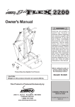
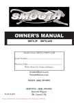
“BEFORE YOU BEGIN”
Thank you for choosing the 2 in 1 Recumbent
Too often, our busy lifestyles limit our time and
Elliptical / Bike. We take great pride in producing this
opportunity to exercise. This equipment will provide a
quality product and hope it will provide you many
convenient and simple way to begin your journey of
hours of quality exercise to making you look and feel
achieving a happier and healthier lifestyle.
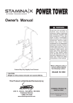
Before reading further, please review the drawing
better.
below and familiarize yourself with the main parts of
Yes, it's a proven fact that a regular exercise
program can improve your physical and mental health. the V2300.. Read this manual carefully before using
the equipment.
Console
Handlebar Assembly
Back Cushion
Pulse
Upright Post
Sensor
Seat Carriage
Assembly
Main Frame
Front Stabilizer
Locking Knob
Pedal
Rear Stabilizer &
Adjustable EndCaps
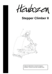
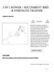
THE FOLLOWING TOOLS ARE INCLUDED FOR ASSEMBLY:
MULTI WRENCH TOOL W/
ALLEN WRENCH
PHILLIPS SCREWDRIVER
(5 & 6 mm)
6
“ASSEMBLY INSTRUCTIONS”
USE HARDWARE KIT
A
STEP 1 – Front Stabilizer Assembly
a. Identify the correct direction of the Front Stabilizer (7), there is an “R” decal on the right side of the Front Stabilizer
(7)(NOTE: Right and left orientation is from the seated position).
b. Attach the Front Stabilizer (7) to the Main Frame (1).
“Helpful Hint: Only hand tighten the bolts and fasteners in each step. Wait until the step is completed
before fully tightening the bolts and fasteners”
c.
Attach two Lock Washers (M8)(121) and two Bolts, Socket Head (M8xp1.25x70mm)(162) that secure the Front
Stabilizer (7) to the Main Frame (1).
STEP 2 – Handlebar Assembly
a. Attach the Left Handlebar Assembly (85) to the Mounting Bracket (83) on the right side of the Console and secure
with one Washer (8x23x2.0t)(124), one Lock Washer (M8)(121) and one Adjustment Knob (186).
b. Repeat the above process for the left side.
**Make sure the above parts are tightened before moving on to the next page**
7
“ASSEMBLY INSTRUCTIONS”
USE HARDWARE KIT
A
STEP 3 – Rear Stabilizer Assembly
a. Attach the Rear Stabilizer (8) to the Rear Support Frame Assembly (2).
“Helpful Hint: Only hand tighten the bolts and fasteners in each step. Wait until the step is completed
before fully tightening the bolts and fasteners”
b.
Attach two Carriage Bolts (M8xp1.25x90mm)(164) that secure the Rear Stabilizer (8) to the Rear Support Frame
Assembly (2).
STEP 4 – Leveler Assembly
Thread the Leveler (38) tightly into the Rear Support Frame Assembly (2). **To properly adjust Leveler (38), please
review page 14 of the manual**.
STEP 5 – Rear Support Frame Assembly
a. Connect the Pulse Sensor Wire 3 (182) to the Pulse Sensor Wire 2 (181). Be careful not to pinch the wires.
NOTE: After connecting the wires, slightly and gently pull two sides of wires to test the that the
connectors are properly locket together.
NOTE: Four Nylock Nut (M8xp1.25)(171) will be pre-attached on the front of the Rear
Support Frame Assembly (2).
b. Remove four Nylock Nut (M8xp1.25)(171) from the front of the Rear Support Frame Assembly (2)
c.
Attach the Rear Support Frame Assembly (2) to the Main Frame (1) and reattach the four Nylock Nut
(M8xp1.25)(171). Be careful not to pinch the wires. Fully tighten nuts now.
d. Attach the Connection Cover (27) to the Main Frame (1) using a Screw, Round Head
(M5xp0.8x40mm) (139).
**Make sure the above parts are tightened before moving on to the next page**
8
“ASSEMBLY INSTRUCTIONS”
USE HARDWARE KIT B
STEP 6 – Seat Support Slider Assembly
Slide the Seat Support Slider Assembly (5) into the Outer Seat Support Slider (4) and secure with four Washers
(8x16x2.0t)(123), four Lock Washers (M8)(121), four Bolts, Button Head (M8xp1.25x20mm)(153)
NOTE: Do not fully tighten the above washers, lock washers and bolts until Step. d of STEP 7.
STEP 7 – Seat Carriage Assembly
NOTE: For clear assembly purpose, please notice that the Square
Stoppers (44), Hex Head Bolt (M8)(148) and Nuts (M8)(168)
have been pre-assembled together as the figure shows on the right
a. The Hole 1 of the Seat Carriage Assembly (9):
Follow the figure on the left, slide Seat Carriage Assembly (9) into the Rail
Pivot (3) and secure one Square Stopper (44) and one Bolt, Hex Head
Step a, b.
(M8xp1.25x115mm)(148) through the Hole 1 of the Seat Carriage Assembly (9)
with one Square Stopper (44) and one Nut (M8xp1.25)(168).
b. The Hole 2 of Seat Carriage Assembly (9):
Now install one Washer (8x16x2.0t)(123), one Lock Washer (M8)(121) and one Bolt, Socket Head
(M8xp1.25x16mm)(159) through the Hole 2 of Seat Carriage Assembly (9) with one Washer (8x16x2.0t)(123), one
Lock Washer (M8)(121) and one Bolt, Socket Head (M8xp1.25x16mm)(159). Do not tighten bolts until Step d.
c.
Attach the bottom of the front Seat Carriage Assembly (9) and the bottom of the Rail Pivot (3)
with four Washers (8x16x2.0t)(123), four Lock Washers (M8)(121) and four Bolts, Socket Head
(M8xp1.25x16mm)(159) as the figure shows on the left. Do not tighten until Step d.
d. Follow the figure on the right to place the rear side of Seat Carriage Assembly
(9) onto the Seat Support Slider Assembly (5) and Fully tighten with four
Washers (8x16x2.0t)(123), four Lock Washers (M8)(121) and four Bolts,
Step c.
Socket Head (M8xp1.25x16mm)(159). Now completely tighten all the bolts
and screws on the front side of the Seat Carriage Assembly (9). Make sure all
bolts and screws related to STEP 6 and 7 are tightened before moving on to the next page
Step d.
9
“ASSEMBLY INSTRUCTIONS”
USE HARDWARE KIT B
STEP 8 – Short Extension Pulse Wire & Rail Decoration Assembly
a. Follow FIG.1 to plug the Short Extension Pulse Wire (183) into the connector located on the front bottom side of the
Seat Rail (91).
b. Attach the Left Rail Decoration Cover (41) and the Right Rail Decoration Cover (42) to the rear side of the Seat
Rail (91) and secure with one Self-Tapping Screw, Truss Head (M4x20mm)(131) and two Screws, Round Head
(M5xp0.8x15mm)(138).
STEP 9 – Adjusting Handle Assembly
a. Attach the Adjusting Handle (55) to the Adjusting Handle Stand to the proper position.
b. Secure the Adjusting Handle (55) by rotating the Nut (M8)(168) in counterclockwise direction until completely tight
against Adjusting Handle (55). NOTE: Please notice that the Nut (M8)(168) has been pre-assembled on the
Adjusting Handle Stand.
**Make sure the above parts are tightened before moving on to the next page**
10
“ASSEMBLY INSTRUCTIONS”
USE HARDWARE KIT B
STEP 10 – Seat and Seat Handlebar Assembly
a. Locate and secure the Seat Handlebar (11) on the Seat Frame (10) with two
Carriage Bolts (M8xp1.25x50mm)(163) and two Nylock Nuts (M8x1.25)(171).
NOTE: Be careful not to pinch the Pulse Sensor Wire 4 (184).
b. NOTE: Four Nylock Nuts (M8x1.25)(171) are pre-attached on the Seat Carriage
Assembly (9)’s Seat Fixed Stand as the figure shows on the right.
c.
Remove four Nylock Nuts (M8x1.25)(171) from the Seat Fixed Stand and set
aside for the following assembly process.
d. Attach the Seat Frame (10) to the Seat Carriage Assembly (9)’s Seat Fixed Stand and secure with four Nylock
Nuts (M8x1.25)(171).
NOTE: After assembling the Seat Frame, gently shake the Seat Frame to test and make sure the Seat Frame is
firmly secured
e. Place the Seat (56) on the Seat Frame (10) and secure with four Bolts, Socket Head (M8xp1.25x40mm)(161).
f.
Attach the Back Cushion (57) to the Seat Frame (10) and secure with two Bolt, Button Head
(M8xp1.25x40mm)(155), two Nylock Nut (M8x1.25)(171) and two Screw Caps (58).
g. Follow FIG.2 to plug the Pulse Sensor Wire 4 (184) into the connector A located on the left side of the Seat Carriage
Assembly (9) NOTE: Be careful not to pinch the Pulse Sensor Wire 4 (184).
**Make sure the above parts are tightened before moving on to the next page**
11
“ASSEMBLY INSTRUCTIONS”
USE HARDWARE KIT C
Please be sure that Bolt
(157) would screw
through the Shaft
Sleeve (106) inside the
rear end of the Right
Pedal Support Arm
Assembly (14) during
assembly
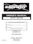
STEP 11 – Pedal Support Arm Assembly
a. NOTE: Two Washers (6x19x2.0t)(122) and two Bolts, Hex Head (M8xp1.25x16mm)(146) are
pre-attached on the Rotation Stand (17) as the figure shows on the right.
b. Remove two Washers (6x19x2.0t)(122) and two Bolts, Hex Head (M8xp1.25x16mm)(146) from the
Rotation Stand (17).
c.
Slide the front side of the Right Pedal Support Arm Assembly (14) onto the Rotation Stand (17)
and secure with two Washers (6x19x2.0t)(122) and two Bolts, Hex Head (M8xp1.25x16mm)(146)
d. Attach the rear side of the Right Pedal Support Arm Assembly (14) to the Right Pivoting Arm (13) and secure with
one Bolt, Button Head (M8xp1.25x90mm)(157), one Shaft Sleeve (106) and one Nylock Nut (M8xp1.25)(171).
NOTE: Be certain that Bolt (157) properly fits through the Shaft Sleeve (106) inside the rear end of the Right Pedal
Support Arm Assembly (14) during assembly.
e. Repeat the above procedure for the left side pedal arm assembly.
**Make sure the above parts are tightened before moving on to the next page**
12
“ASSEMBLY INSTRUCTIONS”
USE HARDWARE KIT C
After fully securing Bolt,
Button Head (155) and
Nylock Nut (M8)(171),
slightly loosen the Bolt (155)
with ¼ turn in the
counter-clockwise direction
to release excess pressure
from Pedal Linkage
STEP 12 – Pedal Linkage and Pedal Assembly
a. Identify the Right Pedal Linkage (19), there is an “R” decal on the Right Pedal Linkage (19).
b. Attach the Right Pedal Linkage (19) to the Pedal Arm Connector (20) and secure with one Bolt, Button Head
(M8xp1.25x40mm)(155) and one Nylock Nut (M8xp1.25)(171). In order to let Pedal Linkage (19) function
smoothly, please do not over-tighten Bolt, Button Head (M8xp1.25x40mm)(155) and Nylock Nut (M8xp1.25)(171).
After fully securing Bolt, Button Head (M8xp1.25x40mm)(155) and Nylock Nut (M8xp1.25)(171), slightly loosen the
Bolt (155) with ¼ turn in the counter-clockwise direction.
c.
NOTE: Notice that Locking Knob (68) and Pedal Linkage Assembly are
pre-assembled together as the figure shows on the right.
d. Remove the Locking Knob (68) from the Pedal Linkage Assembly.
e. Insert the Right Pedal Linkage (19) through the Right Pivoting Arm
Connection (67) and secure with the Locking Knob (68).
f.
Place the Right Pedal (78) onto the Right Pedal Slider (16) and fully secure with
the two Bolts, Round Head (M8xp1.25x16mm)(143).
g. Repeat the above assembly process for the left side pedal linkage and pedal assembly.
STEP 13 – AC Adaptor
a. Connect the Adaptor (185) to the connector located on the front
left side of the Main Frame (1).
b. Plug the Adaptor (185) into an electrical outlet to light up the
console.
13
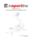
“OPERATION INSTRUCTIONS”
HOW TO ADJUST THE ADJUSTING ENDCAPS OF THE REAR STABILIZER
a. After placing the equipment in the intended location for use, check the
stability of the equipment.
b. To level the equipment, turn one or both of the Adjusting Rear
Stabilizer EndCaps (37) in clockwise or counter-clockwise direction until
the equipment sets on the floor without rocking.
HOW TO ADJUST MAIN FRAME’S LEVELER
a. After placing the equipment in the intended location for use, make sure
the unit is completely level prior to adjusting the center level support.
b. The purpose of the Leveler (38) is to support the middle Main Frame,
adjust Leveler (38) under the Main Frame (1) until it rests firmly on the
floor.
c.
To make the Leveler (38) rests firmly on the floor, turn the Leveler (38)
counter-clockwise until the Leveler (38) touches the floor without
rocking.
HOW TO MOVE THE ITEM SAFELY
Hold the Rear Stabilizer (8) up with two hands and tow the item to the desired place carefully.
Make sure the floor is level while moving the item.
14
“OPERATION INSTRUCTIONS”
HOW TO ADJUST THE SEAT
a. To adjust the seat distance from the pedals, it’s suggested to place your feet
on each pedal.
b. Use your right hand to lift up the Adjusting Handle (A) while using your feet
to slide the seat distance forward or backward until the seat reaches to the
proper position.
c.
Release and secure the Adjusting Handle (A). After releasing the
Adjusting Handle (A), push the seat forward of back until you hear a “click”
sound.
15
“OPERATION INSTRUCTIONS”
HOW TO CHANGE THE WLLIPTICAL BIKE MOTION
STEP MODE:
The item can be used in the ELLIPTICAL mode or the STEP mode.
Refer to the following process to set up the ELLIPTICAL mode or the STEP mode.
a. Before exchanging the ELLIPTICAL mode with the STEP mode, make sure the SIDE YOU ARE ADJUSTING IS IN
the lowest position as the figure shows below
b. Remove the Locking Knob (68) from the Right Pivoting Arm (13)
c.
Attach the Right Pedal Linkage (19) to the Rear Stabilizer (8) and fully tighten the Locking Knob (68)
d. Repeat the above process on the left side
CAUTION: Make sure both Locking Knobs (68) are tightened before exercising
ELLIPTICAL MODE:
16
※ To change to ELLIPTICAL mode, make sure the Pedal Linkage (19) is attached to the Pivoting Arm (13)
17
“CONSOLE INSTRUCTIONS”
Power ON
a. Make sure the item’s
adaptor is correctly
plugged into the
socket
b. Pedaling or pressing
any keys to active
the console. The
console display will
then light up with a
short beep sound,
indicating the
console will be ready
for use
Power Off
The console would
automatically shut off
after 4 minutes of
inactivity
CONSOLE BUTTONS
Press “ENTER/MODE” to confirm desired program and the setting values
1. Press “UP” to select the programs from MANUAL and PROGRAM 1 to PROGRAM 6.
2. Press “UP” to increase the setting value of TIME, DISTANCE, CALORIES, TARGET
HEART RATE, and RESISTANCE LEVEL
1. Press “DOWN” to select the programs from PROGRAM 6 to PROGRAM 1 and MANUAL.
2. Press “DOWN” to decrease the setting value of TIME, DISTANCE, CALORIES, TARGET
HEART RATE, and RESISTANCE LEVEL
Press “ST/SP” to start or stop exercising. Continue pressing “ST/SP”, all the date will return to
zero and the console will return to POWER ON status
a. PULSE RECOVERY button measures how quickly you return to a resting hear rate after
exercising. You could use this button to measure improvement as you get into shape
b. The console will monitor your pulse for 60 seconds and calculate a HEART RATE
RECOVERY value from F1.0 to F6.0. F1.0 is best; F6.0 is worst (For Reference Only)
c.
The readout should only be used as a comparison between workouts. It’s recommended to
use right after any aerobic exercise. Stop exercising before starting the function.
d. If you hold the HEART RATE SENSORS on the handrails with both hands properly, your
pulse will be displayed approximately few seconds after the heart symbol “
18
” is displayed
“CONSOLE INSTRUCTIONS”
CONSOLE FUNCTIONS
SCAN
TIME
Automatically scans TIME, SPEED, CALORIE, PULSE, and DISTANCE in sequence with a
change every five seconds. Press and release the MODE button until the arrow points to
"SCAN”
TIME:
Count Up: If a target time was not selected, TIME will count up from 0:00 to maximum
99:59 minutes
SPEED
DISTANCE
Count Down: If you have set the target time, the console will count down from that
selected target time down to 0:00
Displays the current speed
Count Up: If a target distance was not selected, this value would measure the total
distance from 0:00 to 999 miles
Count Down: If you have set the target distance, the console will count down from that
selected target distance down to 0
CALORIES
CALORIES:
Count Up: If target calories were not selected, this value measures total calories your body
burned during exercise
Count Down: If you have set the preference value of calories, the console will count down
from that selected target calories down to 0
PULSE
HEART RATE:
You must place both of your hands on the Pulse Sensors on the Handlebar. Your pulse
will be displayed approximately few seconds after the heart symbol “
” is displayed
If you do not place your hands correctly and a few seconds passes without a pulse input,
the console will turn off the pulse circuit. Place your hands back on the Pulse Sensors
TENSION
LEVEL
correctly, the pulse readout will appear again
You can change the torque/tension level (from 1 to 8 levels) at any time during workout by
pressing UP or DOWN button
PROGRAM DESCRIPTIONS
MANUAL
PROGRAMS 1-5
PROGRAM 6
(TARGET H.R.)
P1 is a manual program allowing the user to have full manual control of the workload. Use the
"UP" button to increase the Tension Level. Use the "DOWN" button to decrease the Tension
Level
P1 to P5 are preset automatic programs. The profiles are shown on the face of the console. Use
the "UP" button to increase the tension level of the program. Use the "DOWN" button to
decrease the tension level of the program
Program 6 allows you to select the TARGET HEART RATE you desire, from 90 to 220 BPM
(beats per minute) ; 1 BPM increment
If you current pulse > (the value of the TARGET HEART RATE), the console
would decrease one resistance/torque level automatically
If you current pulse < (the value of the TARGET HEART RATE), the console
would increase one resistance/torque level automatically
19
“CONSOLE TROUBLE SHOOTING GUIDE“
PROBLEM
E1
E2
No Hand
Pulse Signal
or incorrect
Hand Pulse
Signal
POSSIBLE CAUSE
SOLUTION
1. Motor Malfunction
Replace Motor
2. Magnetic System
Replace Magnetic System/Flywheel
Malfunction or got stuck
No Motor signal
3. Connection Wires are not Check whether the wires are well-connected or replace the
well-connected or broken broke wires with the new wires
4. Console Malfunction
Replace Console
1. Disconnect the Adaptor or Batteries. Reconnect the Adaptor or Batteries to REBOOT
The Computer cannot the system. Wait two minutes then verify that the system works correctly
make contact with the 2. If IC Chips is not well-assembled. Remove and reinsert the IC Chip
IC Chip
3. If the above solutions couldn’t solve the problem, replace the IC chip with a New IC
Chip
The Computer is
NOT receiving a
Verify that the Hand Pulse Sensor Wire Plugs are connected FIRMLY and correctly
Pulse Signal
The Hand Pulse Sensors will NOT operate correctly if your skin is extremely dry.
Moisten your hands with a little water and try again.
The Computer is
receiving a faint or
intermittent Pulse
Signal
Grasp the Hand Pulse Sensors firmly and avoid moving your hands while exercising.
The computer will need a few seconds to detect and display your correct pulse rate. If
this does not work, try relaxing your grip on the Hand Pulse Sensors
Clean the Hand Pulse Sensors to ensure a good contact between your body and the
Pulse Sensors
The problem still exists, replace the Hand Pulse Sensors.
The LCD
Screen does
not display
anything
The Adaptor is not
plugged in (item
power supply from
Adaptor)
The Computer is
faulty
The Computer isn’t
receiving a signal
from the Speed
The Speed
Display Show Sensor?
“0”
The Sensor is faulty
The Computer is
faulty
Check that the Adaptor is correctly connected to an electrical outlet and plugged into
the socket on the machine correctly
Replace the Computer
Verify the gap between Speed Sensor and the Magnet is 5mm or less
Verify that all the Wire Plugs are connected FIRMLY, correctly and are not damaged
Verify that the Sensor Magnet is installed correctly
Replace the Speed Sensor
Replace the Computer
20
“CONSOLE TROUBLE SHOOTING GUIDE“
PROBLEM
The LCD
Screen
Partially
Displays
POSSIBLE CAUSE
1. The connection
between the
Circuit Board and
the LCD
Membrane is
loose.
2. Gently press
down on the LCD
Screen, if the
partial display
disappears, then
it is a connection
problem
The Rubber
Membranes between
the Circuit Board and
the LCD Screen is
misaligned/not in a
same line. You might
be able to see that
the LCD Screen is on
a slight angle and
NOT inline or parallel
with the Console
Cover
The Computer is
faulty
SOLUTION
Verify that the Circuit Board is securely fastened to the Computer Case. Retighten the
Screws. Take care NOT to over tighten the Screws as this may destroy the Circuit
Board. You just need to keep the Circuit Board firm, STOP tightening screw when you
meet resistance
1. Open the Console.
2. Remove the Circuit Board’s Screws, gently remove the Circuit Board, Re-align the
LCD screen and the Rubber Membrane.
3. Reassemble the Circuit Board and taking care not to bump or knock the Rubber
Membrane out of alignment before the Circuit Board Screws are tight. You just
need to keep the Circuit Board firm, STOP tightening screws when you meet
resistance
Replace the Computer
21
“CONDITIONING GUIDELINES”
How you begin your exercise program depends on your physical condition. If you have been inactive for several
years, or are severely overweight, you must slowly and increase your time on the 2 in 1 Elliptical / Bike
gradually: a few minutes per workout.
Initially, you may be able to exercise only for a few minutes in your target zone, however, your aerobic fitness
will improve over the next six to eight weeks. Don’t be discouraged if it takes longer. It’s important to work at
your own pace. Ultimately, you’ll be able to exercise continuously for 30 minutes. The better your aerobic fitness,
the harder you will have to work to stay in your target zone. Please remember these essentials:
˙ Have your doctor review your training and diet programs to advise you of a workout routine you should
adopt.
˙ Begin your training program slowly with realistic goals that have been set by you and your doctor.
˙ Monitor your pulse frequently. Establish your target heart rate base on your age and condition.
˙ Set up your 2 in 1 Elliptical / Bike a flat, even surface at least 3 feet from walls and furniture.
EXERCISE INTENSITY
To maximize the benefits of exercising, it is important to exercise with the proper intensity. The proper intensity
level can be found by using your heart rate as a guide. For effective aerobic exercise, your heart rate should be
maintained at a level between 70% and 85% of your maximum heart rate as you exercise. This is known as
your target zone. You can find your target zone in the table below. Target zones are listed for both
unconditioned and conditioned persons according to age.
Age
Target Heart Rate Zone Average Max. Heart
(55% ~ 90% of Max.
Rate 100%
Heart Rate)
20
25
30
35
40
45
50
55
60
65
70
110-180 beats per minute
107-175 beats per minute
105-171 beats per minute
102-166 beats per minute
99-162 beats per minute
97-157 beats per minute
94-153 beats per minute
91-148 beats per minute
88-144 beats per minute
85-139 beats per minute
83-135 beats per minute
200 beats per minute
195 beats per minute
190 beats per minute
185 beats per minute
180 beats per minute
175 beats per minute
170 beats per minute
165 beats per minute
160 beats per minute
155 beats per minute
150 beats per minute
During the first few months of your exercise
program, keep your heart rate near the low end of
your target zone as you exercise. After a few
months, your heart rate can be increased gradually
until it is near the middle of your target zone as you
exercise.
To measure your
heart rate
manually, stop
exercising but
continue moving
your legs or
walking around and place two fingers on your wrist. Take a six-second heartbeat count and multiply the results
by 10 to find your heart rate. For example, if your six-second heartbeat count is 14, your heart rate is 140 beats
per minute. (A six-second count is used because your heart rate will drop rapidly when you stop exercising.)
Adjust the intensity of your exercise until your heart rate is at the proper level.
22
“WARM-UP AND COOL-DOWN”
Warm-up The purpose of warming up is to prepare your body for exercise and to minimize injuries. Warm up for
two to five minutes before strength-training or aerobic exercising. Perform activities that raise your heart rate
and warm the working muscles. Activities may include brisk walking, jogging, jumping jacks, jump rope, and
running in place.
Stretching Stretching while your muscles are warm after a proper warm-up and again after your strength or
aerobic training session is very important. Muscles stretch more easily at these times because of their elevated
temperature, which greatly reduces the risk of injury. Stretches should be held for 15 to 30 seconds. Do not
bounce.
Suggested Stretching Exercises
Lower Body Stretch
Place feet shoulder-width
apart and lean forward. Keep
this position for 30 seconds
using the body as a natural
weight to stretch the backs of
the legs.
DO NOT BOUNCE!
When the pull on the back of
the legs lessen, try a lower
position gradually.
h
Floor Stretch
While sitting on the floor, open
the legs as wide as possible.
Stretch the upper body toward
the knee on the right leg by
using your arms to pull your
chest to your thighs. Hold this
stretch 10 to 30 seconds.
DO NOT BOUNCE!
Do this stretch 10 times.
Repeat the stretch with the left
leg.
Bent Torso Pulls
While sitting on the floor,
have legs apart one leg
straight and one knee bent.
Pull the chest down to touch
the thigh on the leg that is
bent and twist at the waist.
Hold this position at least 10
seconds. Repeat 10 times
on each side.
Bent Over Leg Stretch
Stand with feet shoulder-width
apart and lean forward as
illustrated. Using the arms,
gently pull the upper body
towards the right leg. Let the
head hand down. DO NOT
BOUNCE! Hold the position a
minimum of 10 seconds.
Repeat pulling the upper body
to the left leg. Do this stretch
several times slowly.
Remember always to check with your physician before starting any exercise program.
Cool-Down The purpose of cooling down is to return the body to its normal, or near normal, resting state at the
end of each exercise session. A proper cool-down lowers your heart rate and allows blood to return to the heart.
Your cool-down should include the stretches listed above and should be completed after each strength-training
session.
23
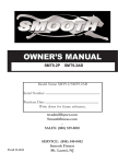
“PRODUCT PARTS DRAWING (A)”
24
“PRODUCT PARTS DRAWING (B)”
25
“PART LIST”
NO.
Item Name
Q'TY
NO.
Item Name
Q'TY
1
Main Frame
1
34 Bearing Housing
4
2
Rear Support Frame
1
35 Transportation Wheel (L&R)
2
3
Rail Pivot
1
36 Round EndCap
2
4
Outer Seat Support Slider
1
37 Adjusting Rear Stabilizer EndCap
2
5
Inner Seat Support Slider
1
38 leveler
1
6
Handlebar (L&R)
2
39 Bushing (60x10mm)
4
7
Front Stabilizer
1
40 Slider Sleeve
1
8
Rear Stabilizer
1
41 Left Rail Decoration Cover
1
9
Seat Carriage
1
42 Right Rail Decoration Cover
1
10 Seat Frame
1
43 Rail Connection Cap
1
11 Seat Handlebar
1
44 Square Stopper
4
12 Left Pivoting Arm
1
45 Console Upper Cover
1
13 Right Pivoting Arm
1
46 Console Bottom Cover
1
14 Pedal Support Arm (L&R)
2
47 Round Plug
2
15 Left Pedal Slider
1
48 Handlebar Foam Grip (L&R)
2
16 Right Pedal Slider
1
49 Idler Wheel
1
17 Rotation Stand
2
50 Left Seat Carriage Cover
1
18 Left Pedal Linkage
1
51 Right Seat Carriage Cover
1
19 Right Pedal Linkage
1
52 Seat Fixed Wheel
1
20 Pedal Arm Connector
4
53 Roller (37.7mm)
4
21 Crank Cover (L&R)
2
54 Square Plug (25x75mm)
1
22 Left Chain Cover
1
55 Adjusting Handle
1
23 Right Chain Cover
1
56 Seat
1
1
57 Back Cushion
1
25 Left Rear Chain Cover
1
58 Screw Cap
2
26 Right Rear Chain Cover
1
59 Round Plug (25.4mm)
4
27 Connection Cover
1
60 Square Plug (20x40mm)
1
28 Top Front Decoration Cover
1
61 Button Plug (31.8mm)
2
29 Top Rear Decoration Cover
1
62 Hand Pulse Sensor (L&R)
2
30 Long Timing Belt
1
63 Seat Handlebar Foam Grip (L&R)
2
31 V-Ribbed Belt for Pulley
1
64 Pivoting Arm Pushing (A)
2
32 Pulley
1
65 Pivoting Arm Pushing (B)
2
33 Magnet
1
66 Bushing Cap
2
24
Decoration Cover for Carriage
Slider
26
PART LIST”
NO.
Item Name
Q'TY
NO.
Item Name
Q'TY
67 Pivoting Arm Connector (L&R)
2
100 Spring for Fixing Pin
1
68 Locking Knob (L&R)
2
101 Spring for Adjusting Handle Stand
1
69 Bushing (25.4x12mm)
4
102 Bushing for Seat Wheel
2
70 Bushing (25.4x16.5mm)
4
103 Spacer (8×12×6.5mm)
4
71 Bushing (38.5x12mm)
4
104 Spacer (8×12×7.5mm)
8
72 Left Rail Connection Cap
2
105 Spacer (8.2×12×59mm)
2
73 Right Rail Connection Cap
2
106 Shaft Sleeve (8.2×12×74mm)
2
74 Rail Sleeve
4
107 Spacer (10×14×21mm)
2
75 Rail Connection Cap
2
108 Key (6×6×16mm)
2
76 Bushing (38.5x17mm)
4
109 Bearing (6002)
2
77 Roller (37.5mm)
8
110 Bearing (6004z)
4
78 Pedal (L&R)
2
111 Internal Retaining Ring
2
79 Aluminum Upright
2
112 C-Ring
5
80 Handlebar Axle
1
113 E-Ring
4
81 Timing Pulley
2
114 Eye Bolt (Swivel)
2
82 Pulley Cap
2
115 Eye Bolt (50mm)
2
83 Mounting Bracket
2
116 Eye Bolt (67mm)
2
84 Left Handle Arm
1
117 Tension Bracket
2
85 Right Handle Arm
1
118
86 Handle Bracket
2
119 Lock Washer (M5)
6
87 Motor Cable
1
120 Lock Washer (M6)
2
88 Flywheel
1
121 Lock Washer (M8)
34
89 Crank Axle
1
122 Washer (6×19×2.0t)
2
90 Crank
2
123 Washer (8×16×2.0t)
16
91 Seat Rail
1
124 Washer (8×26×2.0t)
2
92 Pedal Rail
2
125 Washer (10×23×2.0t)
9
93 Adjustment Bracket for Backrest
1
127 Washer (17×33×0.5t)
2
94 Axle for Braking
1
128 Washer (17×33×1.0t)
6
95 Adjusting Handle Stand
1
97 Fixing Pin
1
98 Axle for Sliding Track
1
99 Linkage Connector
2
Collar Screw, Button Head
(M8×p1.25×7.5mm)
Self-Tapping Screw, Flat Head
(M3.5×25mm)
Self-Tapping Screw, Flat Head
130
(M4×20mm)
Self-Tapping Screw, Truss Head
131
(M4×20mm)
Self-Tapping Screw, Truss Head
132
(M5×12mm)
129
27
2
5
6
19
2
PART LIST”
NO.
Item Name
Self-Tapping Screw, Truss Head
(M5×18mm)
Self-Tapping Screw, Truss Head
134
(M5×25mm)
Self-Tapping Screw, Button Head
135
(M4×15mm)
133
Q'TY
15
4
6
136 Screw, Pan Head (M5x12mm)
6
138 Screw, Round Head (M5×p0.8×15mm)
10
139 Screw, Round Head (M5×p0.8×40mm)
1
140 Bolt, Round Head (M6×p1.0×15mm)
4
141 Bolt, Round Head (M6×p1.0×25mm)
2
142 Bolt, Round Head (M6×p1.0×30mm)
1
143 Bolt, Round Head (M8×p1.25×16mm)
4
144
Bolt, Button Socket Head
(M8×p1.25×25mm)
NO.
12
145 Bolt, Thin Hex Head (M8×p1.25×16mm)
4
146 Bolt, Hex Head (M8×p1.25×16mm)
8
147 Bolt, Hex Head (M8×p1.25×60mm)
4
148 Bolt, Hex Head (M8×p1.25×115mm)
2
149 Bolt, Hex Head (M10×p1.5×85mm)
1
150 Bolt, Hex Head (M10×p1.25×115mm)
2
151 Bolt, Button Head (M6×p1.0×20mm)
4
152 Bolt, Button Head (M8×p1.25×16mm)
4
153 Bolt, Button Head (M8×p1.25×20mm)
4
155 Bolt, Button Head (M8×p1.25×40mm)
6
156 Bolt, Button Head (M8×p1.25×75mm)
2
157 Bolt, Button Head (M8×p1.25×90mm)
2
158 Bolt, Socket Head (M6×p1.0×15mm)
2
159 Bolt, Socket Head (M8×p1.25×16mm)
10
160 Bolt, Socket Head (M8×p1.25×25mm)
4
161 Bolt, Socket Head (M8×p1.25×40mm)
4
162 Bolt, Socket Head (M8×p1.25×70mm)
2
163 Carriage Bolt (M8×p1.25×50mm)
2
Q'TY
164 Carriage Bolt (M8×p1.25×90mm)
2
165 Bolt, Button Head (M6×p1.0×40mm)
2
166 Grub Screw
2
167 Nut (M6×p1.0)
2
168 Nut (M8×p1.25)
3
169 Nylock Nut (M5×p0.8)
1
170 Nylock Nut (M6×p1.0)
5
171 Nylock Nut (M8×p1.25)
24
172 Thin Nylock Nut (M8×p1.25)
16
173 Nylock Nut (M10×p1.5)
3
174 Flange Nut (M10×p1.25)
2
175 Flange Nut w/black color (M10×p1.25)
2
176 Motor
1
177 Front Connection Wire
1
178 Rear Connection Wire
1
179 Sensor Wire
1
180 Pulse Sensor Wire 1
1
181 Pulse Sensor Wire 2
1
182 Pulse Sensor Wire 3
1
183 Short Extension Pulse Wire
1
184 Pulse Sensor Wire 4
1
185 Adaptor
1
186 Adjustment Knob
2
187
28
Item Name
Self-Tapping Screw, Truss Head
(M4×12mm)
4
LIMITED HOME USE WARRANTY – SMOOTH FITNESS Bicycle Warranty
Warranty Coverage: Smooth Fitness, Inc. ("Smooth Fitness") warrants to the original owner that each new product to be free from defects in workmanship and
material, under normal use and conditions.
Period of Coverage: The Warranty on this product runs from the date of original purchase using the following schedule:
Model Name
V2300
V2300
Frame
Lifetime
Lifetime
Resistance Assembly
Lifetime
Lifetime
Parts & Electronics
7 years
7 years
Labor
2 year
1 year
Labor: Smooth Fitness will reimburse for labor costs for Two (2) years*. Smooth Fitness reserves the right to either:
Hire and reimburse an independent service technician, who will come into the home for the repair,
OR
In the event that there is not an available certified Smooth Fitness service technician, Smooth will send the part directly to the consumer and will pay $75 US per
occurrence for the labor costs of such repair. If multiple repair attempts must be made for one reported problem, Smooth will only reimburse once per occurrence.
Smooth Fitness reserves the right to inspect damaged parts for misuse. Your Original Receipt is proof of purchase and should be kept with the product manual. You may
be required to show proof of purchase prior to warranty service being initiated.
Remedy Provided by Smooth Fitness: Smooth Fitness will provide a replacement part free of charge if a defect is found during the Warranty period. Smooth Fitness
may at its discretion, choose to provide any of following parts or repair options. In the event that a part is determined in need of replacement, upon receipt of the part by
Smooth Fitness, Smooth Fitness may send out the part by UPS ground or another such carrier directly to the customer’s home.
Any redemption may be by repair or replacement of the affected parts and/or product at the sole discretion of Smooth Fitness, by personnel approved by Smooth
Fitness.
Parts repaired or replaced pursuant to this Warranty shall be warranted for the unexpired portion of the Warranty applying to the original product. Any technical advice
furnished before or after delivery in regard to the use or application of Smooth Fitness products is furnished without charge and on the basis that it represents Smooth
Fitness' best judgment under the circumstances but that the advice is used at your sole risk.
Procedure for Obtaining Your Remedy Under This Warranty: To obtain service on a Smooth Fitness product, call Smooth Fitness. In the instance that service is not
available in an area, Smooth Fitness, at its discretion, can either 1) find a service technician in your area to perform warranty service, 2) have a local dealer perform
warranty service, or 3) send the warranty parts to you and reimburse as described above. To help the technician assist you, please have the following information
ready:
•
Model name or number from the cover of the manual;
•
Serial number located on the frame of the unit; and
•
The part description and the order number.
Limitations on Warranty: This Warranty does not cover any problems, damages or failures that are caused by accident, improper assembly, failure to observe
cautionary labels on the product, failure to operate the product correctly, power grid failures or spikes from your local electricity provider, abuse or freight damage.
Smooth Fitness does not warrant against any damage or defects that may result from repair or alterations made to the product by an unauthorized repair facility. In
order for this warranty to be valid, all Smooth Fitness and EVO Fitness exercise equipment must be stored and used in a fully finished and livable room within the
residence (not including an indoor swimming pool room and areas with excessive humidity).
This Warranty shall terminate if you sell or otherwise transfer this product. This Warranty does not apply to any product shipped or handled outside of the United States
or Canada. This Warranty does not apply if the product is used as a rental product or in commercial use. Consequential and incidental damages are not recoverable
under this Warranty. (Some states do not allow the exclusion or limitation of incidental or consequential damages, so the above limitation or exclusion may not apply to
you.)
THIS WARRANTY IS EXPRESSLY IN LIEU OF ALL OTHER EXPRESS WARRANTIES. ALL IMPLIED WARRANTIES,
INCLUDING WARRANTIES OF MERCHANTABILITY OR FITNESS FOR ANY PARTICULAR PURPOSE, ARE LIMITED IN DURATION TO TWO (2)
YEARS* FROM THE EFFECTIVE DATE OF THIS WARRANTY. SMOOTH FITNESS IS NOT LIABLE FOR CONSEQUENTIAL OR INCIDENTAL
DAMAGES RESULTING FROM ANY DEFECT IN PARTS NOR FOR ANY BREACH OF EXPRESS OR IMPLIED WARRANTIES. SMOOTH FITNESS' SOLE
LIABILITY UNDER THIS WARRANTY IS LIMITED TO THE TERMS DESCRIBED IN THIS FORM. THIS WARRANTY GIVES YOU SPECIFIC LEGAL
RIGHTS, AND YOU MAY ALSO HAVE OTHER RIGHTS WHICH VARY FROM STATE TO STATE.
*Two year labor is valid only with the continental United States; Canadian labor warranties are valid for the period of 1 year from date of purchase.
FORM WS-1 (rev. 03/2008)
29