1
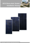
Installation Manual and User Manual for
BYD Double Glass Photovoltaic Modules
Shanghai BYD Co., Ltd.
ADD:No.999 Xiangjing Road,Songjiang
Shanghai, P.R.China
TEL:+86-21-5777 8888
FAX:+86-21-5777 5086
www.byd.com.cn
BYD COMPANY LIMITED
Rev. Feb. 11th 2014
CONTENT
Foreword ............................................................................................................................................................................................................................................... 3 1. Product identification ...................................................................................................................................................................................................................... 3 1.1 Label .............................................................................................................................................................................................................................................................. 3 1.2 Barcode ......................................................................................................................................................................................................................................................... 3 2. Transportation and storage manual .............................................................................................................................................................................................. 4 3. Installation ........................................................................................................................................................................................................................................ 4 3.1 Warning ......................................................................................................................................................................................................................................................... 4 3.2 Mechanical installation ............................................................................................................................................................................................. 错误!未定义书签。 3.2.1 Mounting system ................................................................................................................................................................................................ 错误!未定义书签。 3.2.2 Clamping ............................................................................................................................................................................................................. 错误!未定义书签。 3.2.3 Insertion system ................................................................................................................................................................................................. 错误!未定义书签。 3.3 Electric installation ....................................................................................................................................................................................................................................... 8 3.3.1 Grounding .............................................................................................................................................................................................................................................. 8 3.3.2 General Installation .............................................................................................................................................................................................................................. 9 4. Maintenance and Care .................................................................................................................................................................................................................. 10 4.1General Maintenance ................................................................................................................................................................................................................................. 10 4.2 Module Cleaning ........................................................................................................................................................................................................................................ 11 5.Claim .............................................................................................................................................................................................................................................. 11 2
BYD COMPANY LIMITED
Foreword
1. Product identification
This manual describes the transportation, installation and
maintenance of PV double glass modules (hereafter referred to as
“module”). Please read this manual carefully before installing and using
the modules. Please get in touch with the provider if you have any
questions.
This manual applies to all the standard modules of BYD Company
Limited.
Keep this guide in a safe place for future reference (care and
maintenance) and in case of sale or disposal of the modules.
1.1 Label
Rev. Feb. 11th 2014
The label shows the product type, rated power, rated current, rated
voltage, open circuit voltage, short circuit current, weight, dimensions
etc.;
1.2 Barcode
Each module has only one bar code as shown below:
SH 140107 P636 ASKCD 001
SH——Manufacturer location, Shanghai;
140107——Date(YYMMDD;
P——“P” for Poly –Si, “M” for Mono–Si, “L” for Mono-like Si;
6——“6” for the cell dimension of 156*156mm,“5” for the cell
dimension of 125*125mm;
36——the voltage of the modules;
ASKC——Engineering Code ,referring to different shifts, materials
etc;
D—“D” for Double Glass module;
001——Number of product components, three digit sequence 0 to
999 for sequential production starting on each new day of production at
001.
NOTE: All statements in this manual refer to our 3 bus-bar
polycrystalline cell PV modules as well as to our monocrystalline
cell modules. The illustrations in this manual, which show 2
bus-bar cell PV modules, are only used for reference purposes.
3
BYD COMPANY LIMITED
2. Transportation and storage manual
Rev. Feb. 11th 2014
(4) Under certain conditions, the module might produce a higher
electric current and/or voltage than measured under standard test
conditions. Accordingly, the values of Isc and Voc marked on this module
should be multiplied by 1.25 when determining the component voltage
ratings, conductor current ratings, fuse sizes and size of controls
relating to the PV output.
(5) The installation work of the PV array can only be done under
the protection of sun-sheltering covers or sunshades, and only qualified
persons should install modules or perform maintenance work.
(6) Systems should be installed by qualified personnel only and at
least by two persons. The system involves electricity and can be
dangerous if the personnel are not familiar with the appropriate safety
procedures.
(7) Follow the recommendations of the battery manufacturer if
batteries are used with the modules. Please observe national and local
laws and regulations when installing modules. If required, an
architecture license should be obtained before carrying out this work.
(8) Please unpack carefully.
(9) A visual inspection should be carried out before installation, in
order to make sure that there is no defect in the packing, the junction
box or on the surface of module.
(10)The user should design and select a metallic bracket for
installing that is suitable to bear the weight of the PV modules. The
brackets should be selected by the user according to their destined
places of installation, such as open land or a rooftop. For safety
reasons, all brackets should be grounded. In order to insure good
Please observe the following criteria after packing:
(1) Don’t tilt the packing boxes for more than 15° during handing.
(2)Please follow the instruction labels “up” and “down” during
placing the packing boxes and avoid placing them upside down during
transit.
(3)Be careful while handing the boxes during transit, and avoid
heavy pressure or jolting of the boxes.
(4)The packing boxes should be protected from rain.
(5)Transportation conditions should conform to the requirements of
the packing boxes and of the modules regarding their environmental
conditions.
3. Installation
3.1 Warning
(1) Do not use mirrors or other magnifiers to artificially concentrate
sunlight on the module.
(2) Do not touch the connectors with bare hands and use insulated
tools during electrical work.
(3) Although the glass surface of the modules is rather durable and
able to withstand pressure, the glass might break (and the module will
no longer work properly), if it is dropped or hit by tools or other heavy
objects.
4
BYD COMPANY LIMITED
conductivity, electroplated brackets should be used.
(11)As a general rule, PV modules should be installed in a location
where they will receive maximum sunlight throughout the year. In the
Northern Hemisphere, the modules should typically face south, and in
the Southern Hemisphere, the modules should typically face north.
When choosing a site, avoid trees, buildings or other obstructions,
which might block the sunrays. When selecting a clamping or insertion
system, appropriate anticorrosive brackets should be selected
according to the specification of the module.
(12) Put the modules on the frame and tighten the screws after
putting on the underlying washers. Don't cover the drain holes with
other components when installing the modules. The junction box should
be placed at the top of the module in order to facilitate correct
positioning of ventilation holes.
(13)Don’t grasp the junction box or cables during the installation
process.
(14) In case of installing the module on a roof top, the roof top
should be made fire-resistant first. Do not use modules near equipment
or in places where flammable gases may be generated.
(15)In case of roof top installation, the PV array should fulfill the
requirements regarding fire resistance of the norm IEC 61730-2.
(16)The ambient temperature range at the location of installation
should not exceed -40°C ~+85°C.
(17) Do not connect/disconnect modules under load.
Rev. Feb. 11th 2014
DANGER: One single module may generate more than 30V DC
when its front is exposed to direct sunlight. If modules are
connected in series, the total voltage is equal to the sum of the
partial voltages of each module. If modules are connected in parallel, the total
current is equal to the sum of the partial currents of each module. Therefore
direct contact should be avoided after installing a greater number of modules
in series or parallel, in order to avoid electric shocks.
CAUTION: Please unpack the module in an appropriate
environment, and use special tools. The modules need to be
kept water-proof and damp-proof.
3.2 Mechanical Installation
3.2.1. Mounting system for 60 cells double glass module
Four stainless steel backblocks are stick to backside of double glass
modules on two metallic brackets. The system can withstand 5400 Pa
mechanical load. The positions of the backblocks are shown in Fig.1
and the structure of the backblock is shown in Fig.2.
5
BYD COMPANY LIMITED
Rev. Feb. 11th 2014
Fig. 2 The structure of the backblocks
990
High strength high sticking long life durability silicone is used to
stick the backblocks to the backside of the modules. M6 type threaded
tubular rivets (GB/T 17880.1-1999 or UNI 9201-1988 Threaded tubular
rivets with cylindrical head) are mounted in the center of the
backblocks. The material of the rivets is stainless steel. The
performance stage is 8.8. The bolt tightening torque of the joint is in the
range of 16 to 26 N·M. The rivet nuts can only be changed together with
the backblock when got invalidated. The bolts can be changed
conveniently if necessary.
One module is fastened on two U-shape steel brackets by four M6 bolts
to the rivets in the backblocks, see in Fig.3 and Fig.4. Four convex parts
are designed to help locating the modules before fastening the bolts.
There are ±2mm tolerance for mounting the modules. The direction of
the modules can only be changed by adjusting the brackets.
Junction box
500
4-R
5
10
90
90
900
1637
1650
Mounting backblock
Scupper
A A
495
90
10
Fig.1 Array of backblocks on the module
90
6
BYD COMPANY LIMITED
Rev. Feb. 11th 2014
Since glass and steel have different thermal conductivity, the heat
stress of the module surfaces will be changed outdoor. Therefore,
please locate the site of the brackets precisely to limit the bending
height in one percent of the edge length. The maximum values are
16mm and 10mm for the long edge and short edge respectively. The
bending height on the diagonal should be limited in 30mm.
The modules can be mounted along the long edge or the short
edge as required.
Fig.3 Two double glass modules are mounted on the brackets.
Fig. 5 Two modules are mounted along the long edge
3.2.2 Mounting system for 72 cells double glass module
The modules are also fastened by bolts to rivets like 60 cells modules,
as is shown in Fig. 6 and 7.
Fig.4 Backblocks fastened on U-shape brackets by bolt
7
BYD COMPANY LIMITED
Rev. Feb. 11th 2014
990
Junction box
500
5
4-R
10
90
90
1200
1954
1967
Mounting backblock
Fig. 7 Two 72 cell modules are mounted on two brackets
3.3 Electric installation
Scupper
3.3.1 Grounding
A A
(1) The material of all frames of the double glass modules is polymer
with high electric resistance. There is no need of grounding for the
double glass modules. The brackets must be grounded.
(2) When designing the PV systems, inverters with power transformers
should be used.
(3)Please follow local electrical code before installing.
(4) The grounding system must be installed well.
495
Fig. 6 The array of backblocks on 72 cells double glass modules
8
BYD COMPANY LIMITED
Rev. Feb. 11th 2014
at least 40V.
(3) The cable must not be bent or crushed on the direct exit of
the cable screw joint include connecter and box. A minimum
bending radius R≥5×cable diameter must be maintained. The
cable must be routed in a way that tensile stress on the conductor
or connections is prevented. The pictures are as below:
3.3.2 General Installation
(1)When the modules in a PV system are connected in series or
parallel generally, we recommend simple methods of connecting them
in series or parallel as shown below:
Series connection of modules:
Parallel connection of modules
(4) The maximum number of series connected modules depends
on the system design, the type of inverter used and environmental
conditions. Our modules can be used both in 1500V system and 1000V
system. According to the system voltage (1000V) of the IEC standard,
we recommend the maximum number of series connected modules for
each module series as stated below:
(2) The bypass diode should have a Rated Average Forward
Current at least 10A, and a Rated Repetitive Peak Reverse Voltage of
9
BYD COMPANY LIMITED
4. Maintenance and Care
The maximum
Type
Rev. Feb. 11th 2014
number of
modules in series
BYD ***P6-30-DG/M6-30-DG
No more than
/P6C-30-DG/M6C-30-DG
twenty
BYD ***P6-36-DG /M6-36-DG
No more than
/P6C-36-DG /M6C-36-DG
seventeen
4.1General Maintenance
The following inspections of the modules should be carried out in
regular intervals:
(1) Regularly check the mechanical installation of the module.
Check the support equipment for fastness and symptoms of corrosion
or other damages. Check bolts and nuts for loosening, especially the
places with exposure to hard winds or at times of jolting. Ensure that the
fixing is fast and fasten immediately in places with some looseness. If
conditions permit the metal fittings that fasten or support the modules,
such as the bolts and nuts, should be protected from corrosion. A firs
inspection should be carried out 12 months after installation and
inspections every 10 years thereafter.
(2)Regularly check the electric wiring of the modules for reliable
connection to the components of the equipment and the grounding
system. Check regularly, if the value of the grounding resistance is still
reaching the designated requirement, If connections are not fast, fasten
them by soldering. After a thunderstorm or before the start of the stormy
season check the convergence box and the lightning protection
systems installed inside the equipment for loss of function and change
them immediately if necessary.
(3)Check cables, connectors and joints for current leakages and
deal with it, in order to prevent leakage currents caused by rainy or
snowy weather when checking the wiring, people must take insulation
(4)For parallel connection, the current will be added up and the
used connectors will be limited by the number of parallel connection.
The fuse protection needs to be determined as well.
(5)There is no general limitation on the number of parallel
connected modules but the number of modules is determined by
system design parameters such as current or power output. Every PV
array in parallel should install a protection circuit.
(6) Please refer to local laws and regulations to determine the
system wires size, type and temperature. To prevent the cables and the
connectors from overheating, the cross section of the cables and the
capacity of the connectors must be selected to suit the maximum
system short circuit current (the recommended cable cross section is
4mm2 for a single module or a rated current of the connectors of more
than 10A).
NOTE: Please note that the upper temperature limit is 90°C and
100°C for the connectors.
10
BYD COMPANY LIMITED
Rev. Feb. 11th 2014
wiping in order to avoid scratching the module surface so as to affect
the light transmission efficiency. Any power attenuation caused by
scraping the module is beyond our guarantee range. A time of the day
without sunshine or early evening should be chosen as the time for
cleaning, while broad daylight should be avoided. The use of cold water
to clean a PV module heated up sunshine might cause cracks in the
glass cover of the module.
equipment (such as tools and gloves etc,) with them and avoid touching
the bare parts of connectors or joints with bare hand, Check the system
for loosen parts of the connectors and fasten where necessary to
ensure good contact. Wipe the dust from the equipment regularly to
keep it clean.
(4) If the module appears in need of repair, the surface of the
module should be covered with fabric or other material. There is a
danger of high voltage, if the sun ray directly hit the module.
5.Claim
CAUTION: If you come across loose connectors, please
contact professionals and let them carry out maintenance
As the adherence to this manual and the conditions or methods of
installation, operation, use and maintenance of photovoltaic (PV)
products are beyond BYD’s control. BYD does not accept responsibility
and expressly disclaims liability for any loss, damage, or expense
arising out of or in any way connected with incorrect installation,
operation, use or maintenance.
The information in this manual is based on BYD’s knowledge and
experience and is believed to be reliable. This manual provides
reference only, and consumers are free to choose an appropriate way
of installation according to place and environment.
BYD reserves the right to change the manuals, PV products,
specifications and product information sheets without prior notice.
and care.
4.2 Module Cleaning
Excess dirt and dust accumulating on the glass surface of the
module can reduce its power output. Therefore BYD recommends
periodic cleaning of PV modules especially during times when the
modules do not have the expected power output. Please check the
glass surface of the module for cracks and damages before cleaning. If
there are already cracks on the module, please do not clean but inform
the installer or maintenance service provider. Do not wear a watch or
jewellery during cleaning and use a soft cloth to clean the surface from
dust and dirt, In places with dirt that is hard to remove, clear water might
be used first for soaking and then a piece of clean gauze for carefully
wiping up the water. Do not use any hard tools or mordant solution for
NOTE: A note provides information about installation,
operation, or maintenance of the module that is important
to know, but it is not necessarily hazardous.
11
BYD COMPANY LIMITED
CAUTION: A caution message indicates a potential threat to
minor injury, or alerts against behavior that can lead to
property damage.
DANGER: A danger message indicates a hazard in the
immediate area which, if not avoided, can result in death or
serious injury.
12
Rev. Feb. 11th 2014