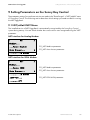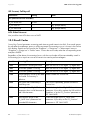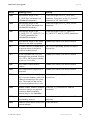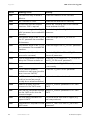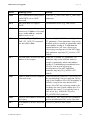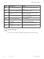
1
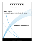
Accessories Solar Datatechnology
NET Piggy-Back
Technical Description
NETPB-TEN081708 | 98-0009733 | Version 3.3
EN
SMA Solar Technology AG
Table of Contents
Table of Contents
1
1.1
1.2
1.3
1.4
Notes on this Manual. . . . . . . . . . . . . . . . . . . . . . . . . . . . . .
Validity . . . . . . . . . . . . . . . . . . . . . . . . . . . . . . . . . . . . . . . . . . . .
Target Group . . . . . . . . . . . . . . . . . . . . . . . . . . . . . . . . . . . . . . .
Storage of the Manual. . . . . . . . . . . . . . . . . . . . . . . . . . . . . . . .
Symbols Used. . . . . . . . . . . . . . . . . . . . . . . . . . . . . . . . . . . . . . .
2
2.1
2.2
Safety . . . . . . . . . . . . . . . . . . . . . . . . . . . . . . . . . . . . . . . . . . 7
Appropriate Usage . . . . . . . . . . . . . . . . . . . . . . . . . . . . . . . . . . 7
Safety Precautions . . . . . . . . . . . . . . . . . . . . . . . . . . . . . . . . . . . 8
3
3.1
3.2
The NET Piggy-Back . . . . . . . . . . . . . . . . . . . . . . . . . . . . . . . 9
Packing List . . . . . . . . . . . . . . . . . . . . . . . . . . . . . . . . . . . . . . . . . 9
Identification . . . . . . . . . . . . . . . . . . . . . . . . . . . . . . . . . . . . . . . 10
4
4.1
Electrical Connection . . . . . . . . . . . . . . . . . . . . . . . . . . . . . 11
Connections . . . . . . . . . . . . . . . . . . . . . . . . . . . . . . . . . . . . . . . 11
4.1.1
4.1.2
NET Socket . . . . . . . . . . . . . . . . . . . . . . . . . . . . . . . . . . . . . . . . . . . . . . . . . . 11
PC (COM2) / AUX (COM3) Serial Interface . . . . . . . . . . . . . . . . . . . . . . . 12
4.2
Connection to the Data Network. . . . . . . . . . . . . . . . . . . . . . . 12
4.2.1
4.2.2
4.2.3
4.2.4
NET Piggy-Back "Analog Modem" Version . . . . . . . . . . . . . . . . . . . . . . . . .
NET Piggy-Back "ISDN" Version . . . . . . . . . . . . . . . . . . . . . . . . . . . . . . . . .
NET Piggy-Back "GSM" Version . . . . . . . . . . . . . . . . . . . . . . . . . . . . . . . . .
NET Piggy-Back "Ethernet" Version . . . . . . . . . . . . . . . . . . . . . . . . . . . . . . .
5
5.1
5.2
5.3
Initial Start-up . . . . . . . . . . . . . . . . . . . . . . . . . . . . . . . . . . . 18
NET Piggy-Back "Analog Modem" Version . . . . . . . . . . . . . . . 18
NET Piggy-Back "ISDN" Version . . . . . . . . . . . . . . . . . . . . . . . 19
NET Piggy-Back "GSM" Version . . . . . . . . . . . . . . . . . . . . . . . 19
5.3.1
5.3.2
5.3.3
Outgoing Data Connection . . . . . . . . . . . . . . . . . . . . . . . . . . . . . . . . . . . . . 20
Incoming Data Connection . . . . . . . . . . . . . . . . . . . . . . . . . . . . . . . . . . . . . 20
Incoming and Outgoing Data Connection . . . . . . . . . . . . . . . . . . . . . . . . . 21
Technical Description
NETPB-TEN081708
5
5
5
5
5
12
14
15
16
3
Table of Contents
SMA Solar Technology AG
5.4
NET Piggy-Back "Ethernet" Version . . . . . . . . . . . . . . . . . . . . . 22
6
6.1
6.2
Configuration for E-mail Transmission . . . . . . . . . . . . . . . 24
E-mail Recipient of your Choice . . . . . . . . . . . . . . . . . . . . . . . . 24
Data Transmission to Sunny Portal . . . . . . . . . . . . . . . . . . . . . . 24
6.2.1
Calculating the Data Volume for Sunny Portal . . . . . . . . . . . . . . . . . . . . . . 24
7
7.1
Parameter List. . . . . . . . . . . . . . . . . . . . . . . . . . . . . . . . . . . 27
Communication Parameters (KO_) . . . . . . . . . . . . . . . . . . . . . 27
7.1.1
7.1.2
7.1.3
7.1.4
7.1.5
General Settings . . . . . . . . . . . . . . . . . . . . . . . . . . . . . . . . . . . . . . . . . . . . . .
NET Piggy-Back "Analog Modem" Version . . . . . . . . . . . . . . . . . . . . . . . . .
NET Piggy-Back "ISDN" Version . . . . . . . . . . . . . . . . . . . . . . . . . . . . . . . . .
NET Piggy-Back "GSM" Version . . . . . . . . . . . . . . . . . . . . . . . . . . . . . . . . .
NET Piggy-Back "Ethernet" Version . . . . . . . . . . . . . . . . . . . . . . . . . . . . . . .
27
27
27
28
28
7.2
Remote Information Parameters (FI_). . . . . . . . . . . . . . . . . . . . 28
7.2.1
7.2.2
7.2.3
7.2.4
7.2.5
General Settings . . . . . . . . . . . . . . . . . . . . . . . . . . . . . . . . . . . . . . . . . . . . . .
Data Transmission to Sunny Portal . . . . . . . . . . . . . . . . . . . . . . . . . . . . . . . .
E-mail Recipient of your Choice . . . . . . . . . . . . . . . . . . . . . . . . . . . . . . . . . .
ISP (Internet Service Provider) . . . . . . . . . . . . . . . . . . . . . . . . . . . . . . . . . . .
SMTP (Mail Server) . . . . . . . . . . . . . . . . . . . . . . . . . . . . . . . . . . . . . . . . . . .
8
Setting Parameters with Sunny Data Control . . . . . . . . . 35
9
9.1
9.2
Setting Parameters on the Sunny Boy Control . . . . . . . . 36
NET/eMail->NET Menu. . . . . . . . . . . . . . . . . . . . . . . . . . . . . . 36
NET/eMail->Remote Info Menu . . . . . . . . . . . . . . . . . . . . . . . 38
9.3
Sending a Test E-mail . . . . . . . . . . . . . . . . . . . . . . . . . . . . . . . . 41
10
10.1
10.2
10.3
Appendix . . . . . . . . . . . . . . . . . . . . . . . . . . . . . . . . . . . . . . 42
Preconfigured Settings . . . . . . . . . . . . . . . . . . . . . . . . . . . . . . . 42
The Access Data of your Provider . . . . . . . . . . . . . . . . . . . . . . 43
Result Codes. . . . . . . . . . . . . . . . . . . . . . . . . . . . . . . . . . . . . . . 45
11
Contact . . . . . . . . . . . . . . . . . . . . . . . . . . . . . . . . . . . . . . . . 50
4
NETPB-TEN081708
28
30
30
33
34
Technical Description
SMA Solar Technology AG
Notes on this Manual
1 Notes on this Manual
1.1 Validity
•
This manual applies to the following devices:
•
Sunny Boy Control (firmware version 4.09 or higher)
•
Sunny Boy Control Plus (firmware version 4.09 or higher)
•
Sunny Central Control (firmware version 4.0 or higher)
•
Analog NET Piggy-Back (firmware version 2.01F or higher)
•
NET Piggy-Back GSM (firmware version 2.01F or higher)
-
The Sunny Central Control is currently unable to send system data to the Sunny Portal.
•
NET Piggy-Back ISDN (firmware version 2.01F or higher)
•
NET Piggy-Back Ethernet (firmware version 1.08F or higher)
1.2 Target Group
This manual is intended for the installer.
1.3 Storage of the Manual
The NET Piggy-Back manual must be stored in the immediate vicinity of the Sunny Boy Control / Plus
or the Sunny Central Control and must be accessible at all times.
1.4 Symbols Used
The following warnings and notes containing general information appear in this document:
DANGER!
DANGER indicates a hazardous situation which, if not avoided, will result in death or
serious injury.
WARNING!
WARNING indicates a hazardous situation which, if not avoided, could result in death
or serious injury.
Technical Description
NETPB-TEN081708
5
Notes on this Manual
SMA Solar Technology AG
CAUTION!
CAUTION indicates a hazardous situation which, if not avoided, could result in minor or
moderate injury.
NOTICE!
NOTICE indicates a situation that can result in property damage if not avoided.
Information
Information provides tips that are valuable for the optimal installation and operation of
your product.
6
NETPB-TEN081708
Technical Description
SMA Solar Technology AG
Safety
2 Safety
2.1 Appropriate Usage
The NET Piggy-Back is an additional module for the Sunny Boy Control that allows you to e-mail the
operating data of your PV system directly to the Sunny Boy Control. The NET Piggy-Back comes in
four different versions. Depending on which version you order, the NET Piggy-Back can send data
using one of the following methods:
•
analog telephone network
•
ISDN
•
GSM (cellular phone network)
•
Ethernet
The Sunny Boy Control automatically sends the yield data of your system as well as any failure
messages to up to three recipients everyday. You can also forward this data to your own cellular
phone with an e-mail-to-SMS service. The Sunny Boy Control with NET Piggy-Back can dial up to
the Internet using any Internet service provider (ISP). For sending e-mails, SMA provides a mail
server free of charge or you can use the SMTP or ASMTP server of your provider.
Besides sending e-mails, the NET Piggy-Back also allows you to dial-in to your PV system with a PC
and a compatible modem. You can therefore use public telephone network to perform remote
diagnostics and configurations.
Establishing a Connection with the ISDN NET Piggy-Back
The ISDN NET Piggy-Back cannot be connected to a Sunny Boy Control via an analog
modem. To establish such a connection, you must use an ISDN modem (terminal adapter)
or an ISDN PC card!
The figure below shows the principle and the possibilities of communication via the NET Piggy-Back.
The NET Piggy-Back can be retrofitted into all Sunny Boy Control (SBCO02) devices and Sunny
Boy Control Plus (SBCOP02) devices with NET sockets.
Technical Description
NETPB-TEN081708
7
SMA Solar Technology AG
Safety
E-mail Formats
Reports can be generated on the following events:
•
System info: report on the energy yields of your system
•
Errors/warnings: report on any errors or warnings which may have occurred
Errors and warnings are always transmitted together in a report. If you configure warnings as 'daily
reports' and errors as 'hourly reports', notification will be sent at the next hour after an error occurs.
This report contains all the errors and warnings that have occurred until the time it is sent. If a
warning is issued, it will be reported at the end of the day.
2.2 Safety Precautions
DANGER!
Danger to life when opening the Sunny Boy Control.
All work on the Sunny Boy Control / Sunny Boy Control Plus and Sunny Central Control
may only be carried out by a qualified electrician.
User Manual Supplement
This document is a supplement to the "Sunny Boy Control/Control Plus" user manual.
8
NETPB-TEN081708
Technical Description
SMA Solar Technology AG
The NET Piggy-Back
3 The NET Piggy-Back
When the NET Piggy-Back is installed, you have the option of having the operating data of your PV
system sent to you by e-mail or forwarded to you by SMS. The NET Piggy-Back offers you
convenient access to the current status and energy yields of your PV system regardless of your actual
location.
This document describes the additional functions that are enabled when the NET Piggy-Back is
installed. It supplements the Sunny Boy Control / Control Plus documentation and contains critical
information for the installer and operator regarding the function, installation and use of the NET
Piggy-Back.
Difference between Sunny Boy Control and Sunny Boy Control Plus
In the remainder of this document the Sunny Boy Control and the Sunny Boy Control Plus
will be differentiated only when necessary. The range of functions with regard to the NET
Piggy-Back is identical for both devices.
3.1 Packing List
NET Piggy-Back "Analog Modem" Version
1
WEBPB-AN2 (NET Piggy-Back "analog modem" version)
1
TAE-N/RJ11
1
Grounding cable
1
Spacer
1
Modular connection cable (5 m, 4 wires)
NET Piggy-Back "ISDN" Version
1
WEBPB-IS1(NET Piggy-Back "ISDN" version)
1
Spacer
1
ISDN connection cable (6 m, 4 wires)
NET Piggy-Back "GSM" Version
1
WEBPB-GS1 (NET Piggy-Back "GSM" version)
1
Spacer
1
Spacer
1
Rod antenna for D/E network
(antenna cable, washer, lock washer, nut, rod antenna)
Technical Description
NETPB-TEN081708
9
The NET Piggy-Back
SMA Solar Technology AG
NET Piggy-Back "Ethernet" Version
1
WEBPB-ET1 (NET Piggy-Back "Ethernet" version)
1
Spacer
1
Patch cable (SFTP, 3 m)
3.2 Identification
You can identify the NET Piggy-Back by the label on the PCB.
10
NETPB-TEN081708
Technical Description
SMA Solar Technology AG
Electrical Connection
4 Electrical Connection
4.1 Connections
4.1.1 NET Socket
The NET Piggy-Back can be retrofitted into all Sunny Boy Control/Control Plus devices or Sunny
Boy Control/Control Plus devices with NET sockets at SMA. An external modem is not required, the
operating data of your PV system are transmitted by the communication module that is integrated in
the NET Piggy-Back. Note the following changes when using a Sunny Boy Control with the NET
Piggy-Back:
•
External modem not required.
•
System monitoring via fax reports is not supported.
Bottom view of Sunny Boy Control with NET socket
Bottom view of Sunny Boy Control Plus with NET socket
Technical Description
NETPB-TEN081708
11
Electrical Connection
SMA Solar Technology AG
4.1.2 PC (COM2) / AUX (COM3) Serial Interface
Installing a NET Piggy-Back will not only enable the NET socket, but also an RS232 port at the PC
port (COM2) of the Sunny Boy Control or the AUX port (COM3) of the Sunny Boy Control Plus.
You can connect a PC equipped with Sunny Data Control or a large display, for instance, to these
enabled ports.
NET Piggy-Back in the Sunny Boy Control enables the RS232 at the PC port
(COM2).
NET Piggy-Back in the Sunny Boy Control Plus enables the RS232 at AUX
(COM3).
4.2 Connection to the Data Network
With the provided connection cable you can connect the NET sockets to the telephone network or
Ethernet. In the GSM version the NET socket is disabled.
4.2.1 NET Piggy-Back "Analog Modem" Version
The accessories provided in the delivery include:
•
Connection cable
5 m, 4-wire, 6-pole modular plug (RJ12) on an 8-pole
modular plug (RJ45)
•
TAE adapter (for Germany)
of 6-pole modular plug (RJ12) on TAE-N
12
NETPB-TEN081708
Technical Description
SMA Solar Technology AG
Electrical Connection
Connecting the Sunny Boy Control to the analog telephone network
Sunny Boy Control
with NET socket
TAE adapter
RJ45 plug
analog
telephone jack
RJ12 plug
Insert the wide 8-pole modular plug into the NET socket of your Sunny Boy Control. Now connect
the thin 6-pole end of the cable to the telephone wall jack. An adapter that makes the modular plug
compatible with TAE-N is included for the TAE jacks commonly found in Germany. Connect it to one
of the two N-coded jacks.
PIN Assignment of the NET Piggy-Back "Analog Modem" Version
Whereas the TAE plug is provided for connecting to the telephone network in Germany, the RJ45
plug is normally used for connecting to all other telephone networks. In special cases a connection
can be made based on the information in the table below or else an adapter must be obtained from
a specialist dealer.
NET
RJ12
TAE
Specification
Description
1
-
-
not used
2
1
-
not used
3
2
5
b2
"Ring" relay
4
3
2
b
b line, also labeled as ring
5
4
1
a
a line, also labeled as tip
6
5
6
a2
"Tip" relay
7
6
-
not used
8
-
-
not used
Technical Description
NETPB-TEN081708
13
SMA Solar Technology AG
Electrical Connection
4.2.2 NET Piggy-Back "ISDN" Version
The accessories provided in the delivery include:
•
ISDN connection cable
6 m, 4-wire, 8-pole modular plug (RJ45) on both ends
Connecting the Sunny Boy Control to the ISDN
Sunny Boy Control with NET socket
ISDN
connection
RJ45 plug
RJ45 plug
Use the provided connection cable to connect the NET socket to the ISDN jack on the NTBA or
telephone system.
PIN Assignment of the NET Socket for ISDN Modems
NET
RJ45
NTBA
Description
1
1
-
not used
2
2
-
not used
3
3
2a
transmitted data plus, also labeled as Tx(+) or SX1
4
4
1a
transmitted data minus, also labeled as Tx(-) or SX2
5
5
1b
received data minus, also labeled as Rx(-) or SR2
6
6
2b
received data plus, also labeled as Rx(+) or SR1
7
7
-
not used
8
8
-
not used
14
NETPB-TEN081708
Technical Description
SMA Solar Technology AG
Electrical Connection
4.2.3 NET Piggy-Back "GSM" Version
The accessories provided in the delivery include:
•
Radio antenna with external thread
To prepare your Sunny Boy Control for use with a GSM NET Piggy-Back, proceed as follows:
DANGER!
Risk of lethal electric shock when opening the Sunny Boy Control.
Open the Sunny Boy Control as described in the Sunny Boy Control manual.
Inserting the SIM Card
Interior view of Sunny Boy Control
Slot for SIM card
Insert your SIM card into the device on the GSM NET Piggy-Back. To do so, you first need to release
the lock and lift up the clamp. Now slide your card into the device and then close and lock it. Make
sure the Sunny Boy Control is properly closed. Reconnect all peripherals.
Dial-In Function for Remote Maintenance
To use the dial-in function for remote maintenance, you need an SIM card with an active
data link. This card is only available from cellular network providers as part of a contract.
If you only want to send e-mails, then you can also use a prepaid card.
Technical Description
NETPB-TEN081708
15
SMA Solar Technology AG
Electrical Connection
Attaching the Antenna
Sunny Boy Control with antenna socket
Radio antenna
Screw the provided radio antenna into the antenna socket in a clockwise direction and tighten it
manually. The device for the antenna is located on the top of your Sunny Boy Control.
4.2.4 NET Piggy-Back "Ethernet" Version
The accessories provided in the delivery include:
•
Cat 5 patch cable
3 m, 8-wire, 8-pole modular plug (RJ45) on both ends
Connecting to a Network
To connect your Sunny Boy Control to an existing network, connect it to your router or switch as
shown below. Use the provided patch cable for this purpose. An example of how to integrate the
Sunny Boy Control in the network can be found in Section 5.4.
Router
Sunny Boy Control with
NET socket
PC with Ethernet card
RJ45 plug
RJ45 plug
16
NETPB-TEN081708
Technical Description
SMA Solar Technology AG
Electrical Connection
Connecting Directly to a PC
If you want to connect your Sunny Boy Control directly to a PC via the NET socket, you need to use
a crossover patch cable (not included in the delivery).
Sunny Boy Control with NET socket
PC with
Ethernet card
RJ45 plug
RJ45 plug
PIN Assignment of the NET Socket for the Ethernet Module
NET
RJ45
Description
1
1
transmitted data plus, also labeled as Tx(+)
2
2
transmitted data minus, also labeled as Tx(-)
3
3
received data plus, also labeled as Rx(+)
4
4
not used
5
5
not used
6
6
received data minus, also labeled as Rx(-)
7
7
not used
8
8
not used
Technical Description
NETPB-TEN081708
17
SMA Solar Technology AG
Initial Start-up
5 Initial Start-up
Once all connections have been properly made, you can switch on the Sunny Boy Control. The NET
Piggy-Back can be configured after the boot process is complete (this can take a few minutes).
Configuring the Sunny Boy Control to send e-mails can be done either on the device itself (see
Section 9) or from a local PC running the Sunny Data Control system monitoring software (see
Section 8).
Password Protection
To make changes in the Sunny Data Control menu or on the Sunny Boy Control itself, the
installer password must be entered first. The passwords are written down a separate
information leaflet included in the Sunny Boy Control delivery package. The default
installer password is only valid until the installer sets his or her own password.
Checklist for Parameter Setting
When configuring the Sunny Boy Control, we recommend that you fill out the enclosed
checklist and perform all the settings on a step by step basis. With the help of this checklist
you should be able to avoid making any incorrect or incomplete settings in the Sunny Boy
Control / Control Plus.
5.1 NET Piggy-Back "Analog Modem" Version
The following basic parameter settings must be made on the Sunny Boy Control / Sunny Boy
Control Plus to enable an incoming and outgoing data link.
Required parameter settings on the device:
•
CO_NET Auto Answer:
-
•
•
The access number of your Internet service provider (ISP).
FI_ISP User ID:
-
•
Set a value greater than "0" here (recommendation: "2").
FI_ISP Phone No:
The user ID that you received from the Internet service provider (ISP).
FI_ISP Password:
-
The password that corresponds to the user ID.
For information on configuring the device for e-mail transmission, see Section 6.
18
NETPB-TEN081708
Technical Description
SMA Solar Technology AG
Initial Start-up
5.2 NET Piggy-Back "ISDN" Version
The following basic parameter settings must be made on the Sunny Boy Control / Sunny Boy
Control Plus to enable an incoming and outgoing data link.
Required parameter settings on the device:
•
CO_NET-ISDN MSN:
-
•
CO_NET Auto Answer:
-
•
The access number of your Internet service provider (ISP).
FI_ISP User ID:
-
•
Set a value greater than "0" here (recommendation: "2").
FI_ISP Phone No:
-
•
Telephone number used to receive calls.
The user ID that you received from the Internet service provider (ISP).
FI_ISP Password:
-
The password that corresponds to the user ID.
For information on configuring the device for e-mail transmission, see Section 6.
5.3 NET Piggy-Back "GSM" Version
In contrast to landline phones, cellular network providers make a clear distinction between
voice services and data services. For example, they provide
different numbers for voice and data with GSM devices.
A separate data number is required for incoming data connections (access by modem) on the data
logger. This can be requested when arranging the contract with the network provider. Retroactive
activation is also possible via telephone by calling the relevant technical service line and stating the
customer password defined in the contract. If in doubt, please consult your cellular network
provider.
Outgoing data connections from the data logger (access to an Internet service provider) are
possible without an additional data number.
If not just outgoing, but also incoming data connections are to be enabled,
a dedicated data number which operates over the CSD data service is an absolute necessity. Other
data services are not supported. A standard SIM card with additional data connectivity always has
two telephone numbers (multi-numbering).
The GSM data service must be activated.
Please note that the GSM data service must be activated
in your contract. If in doubt, please consult your cellular network provider.
Technical Description
NETPB-TEN081708
19
SMA Solar Technology AG
Initial Start-up
5.3.1 Outgoing Data Connection
This data connection method allows you to send your system data by e-mail using your Internet
service provider. You do not require an additional data number.
Prepaid Card
If you would like to use a prepaid card, please consult your cell phone provider in
advance concerning the card's loading options.
Required parameter settings on the device:
•
CO_NET-GSM PIN:
-
•
FI_ISP Phone No:
-
•
The access number of your Internet service provider (ISP).
FI_ISP User ID:
-
•
The respective PIN number of the SIM card.
The user ID that you received from the Internet service provider (ISP).
FI_ISP Password:
-
The password that corresponds to the user ID.
Access Number of your Service Provider
The access number of your Internet service provider depends on the cell network
of your SIM card. You receive this telephone number from your Internet service provider.
For information on configuring the device for e-mail transmission, see Section 6.
5.3.2 Incoming Data Connection
This data connection method allows you to access the system and set system parameters or retrieve
available data from a PC. The SIM card requires a data connection through the CSD data service
in order for the NET Piggy-Back to receive data. Other data services such as GPRS are not
available.
Prepaid Cards
In most cases, prepaid cards cannot be used for this purpose.
If in doubt, please consult your cell phone network provider.
20
NETPB-TEN081708
Technical Description
SMA Solar Technology AG
Initial Start-up
Required parameter settings on the device:
•
CO_NET-GSM PIN:
-
•
The respective PIN number of the SIM card.
CO_NET Auto Answer:
-
Set a value greater than "0" here (recommendation: "2").
For information on configuring the device for e-mail transmission, see Section 6.
5.3.3 Incoming and Outgoing Data Connection
This data connection method is a combination of the two methods described above. This means that
the Sunny Boy Control can automatically send data at regular intervals and using your PC, you can
access the system to set the system parameters. The SIM card requires a data connection through
the CSD data service in order for the NET Piggy-Back to receive data. Other data services such as
GPRS are not available.
Prepaid Cards
In most cases, prepaid cards cannot be used for this purpose.
If in doubt, please consult your cell phone network provider.
Required parameter settings on the device:
•
CO_NET-GSM PIN:
-
•
CO_NET Auto Answer:
-
•
The access number of your Internet service provider (ISP).
FI_ISP User ID:
-
•
Set a value greater than "0" here (recommendation: "2").
FI_ISP Phone No:
-
•
The respective PIN number of the SIM card.
The user ID that you received from the Internet service provider (ISP).
FI_ISP Password:
-
The password that corresponds to the user ID.
Access Number of your Service Provider
The access number of your Internet service provider depends on the cell network
of your SIM card. You receive this telephone number from your Internet service provider.
For information on configuring the device for e-mail transmission, see Section 6.
Technical Description
NETPB-TEN081708
21
SMA Solar Technology AG
Initial Start-up
5.4 NET Piggy-Back "Ethernet" Version
Subnet address of PC and NET Piggy-Back
The IP address of your PC must be in the same subnet as the IP address of the NET PiggyBack (in this case 10.xxx.xxx.xxx).
Example:·IP address: 10.6.1.1·
Subnet: 255.0.0.0
After start-up you should be able to access the Sunny Boy Control at the address 10.170.170.170.
If you want to use a different configuration because, for instance, you are using multiple devices at
the same time or your local network is using a different address range such as Class B or Class C
addresses (see "Example topology for a Class A network" (Page 23)), set the following parameters:
•
CO_NET-ETH IP
-
•
CO_NET-ETH SNET
-
•
Subnet mask
CO_NET-ETH GW
-
•
IP address of the Sunny Boy Control / Sunny Boy Control Plus
Gateway address
CO_NET-ETH DNS
-
IP address of the domain name server
For information on configuring the device for e-mail transmission, see Section 6.
Checking Default Parameters
To check communication based on the default parameters, proceed as follows:
Open a command prompt window on another PC in the network. Enter "ping 10.170.170.170",
which is the default IP address of the Sunny Boy Control.
You should now see the following information on your screen:
22
NETPB-TEN081708
Technical Description
SMA Solar Technology AG
Initial Start-up
Example topology for a Class A network
WAN connection
Router/Gateway (10.0.0.1)
Switch
CO_NET-ETH DNS 0.0.0.0
CO_NET-ETH GW 10.0.0.1
PC1 (10.4.1.3)
CO_NET-ETH IP
10.170.170.170
CO_NET-ETH SNET 255.0.0.0
PC2 (10.5.1.1)
Sunny Boy Control with NET
socket (10.170.170.170)
Address space for local networks
Class
Address space
Subnet mask
A
10.0.0.1 to 10.255.255.254
255.0.0.0
B
172.16.0.1 to 175.31.255.254
255.255.0.0
C
192.168.0.1 to 192.168.255.254
255.255.255.0
Technical Description
NETPB-TEN081708
23
Configuration for E-mail Transmission
SMA Solar Technology AG
6 Configuration for E-mail Transmission
This section will show you how to set the appropriate configuration depending on whether you want
to send data to an e-mail recipient of your choice or directly to the Sunny Portal.
Required Information
The information that is required to send e-mails to an "E-mail recipient of your choice" or
the "Sunny Portal" is listed below. You can also perform additional settings as specified
in Section 7.
6.1 E-mail Recipient of your Choice
•
FI_EMAIL:
-
•
Set this parameter to <activated>.
FI_EMAIL TO:
-
Please enter the e-mail address of the recipient to whom the e-mail is to be sent here.
6.2 Data Transmission to Sunny Portal
•
FI_SPMail:
•
FI_SPMail from:
•
Here you must enter your login, which is the same as the e-mail address you registered in
Sunny Portal.
FI_SPMail to:
-
•
Set the parameter to hours or daily report.
Do not change the e-mail address entered here ([email protected]).
FI_Plant Name1
-
Used to identify your system.
6.2.1 Calculating the Data Volume for Sunny Portal
All the recorded channels of the Sunny Boy Control / Sunny Boy Control Plus with Sunny Portal
Mail (SPMail) will be sent. Since the amount of data in the e-mail is limited, the data volume must
be adjusted to match the recorded channels and measuring interval.
The formulas for calculating the number of channels and the measuring interval for the hourly and
daily reports are described below.
24
NETPB-TEN081708
Technical Description
SMA Solar Technology AG
Configuration for E-mail Transmission
Legend
Variables:
•
K = number of channels
•
MI = measuring interval
•
ED = period of radiation per day – a maximum of 17 hours is assumed here
Constants:
•
61,000 = maximum memory capacity of an e-mail
•
10 = maximum size of a character in Sunny Portal
•
53 = describes the beginning of a row
SP Mail Daily Report
•
Number of channels:
•
A measuring interval of 15 minutes and an assumed radiation period of 17 hours results
in 83 channels.
Measuring interval:
-
If there are 83 channels, the shortest possible measuring interval is 15 minutes.
SP Mail Hourly Report
•
Number of channels:
-
A measuring interval of one minute results in 93 channels.
Technical Description
NETPB-TEN081708
25
Configuration for E-mail Transmission
•
Measuring interval:
-
26
SMA Solar Technology AG
If there are 93 channels, the shortest possible measuring interval is 1 minute.
NETPB-TEN081708
Technical Description
SMA Solar Technology AG
Parameter List
7 Parameter List
7.1 Communication Parameters (KO_)
7.1.1 General Settings
CO_NET Medium
Shows the recognized NET Piggy-Back version. Version
recognition can occur only after the Sunny Boy Control firmware
has been completely loaded and serial communication has been
initialized (up to 2 minutes after it is turned on). "- - -" is displayed
until these conditions are met.
•
---
•
Analog modem
(no module recognized)
•
ISDN
•
GSM
•
Ethernet
7.1.2 NET Piggy-Back "Analog Modem" Version
CO_NET Auto Answer
(0 ... 9 pulses)
Number of ring pulses until a call is answered in the analog
version.
0 = no answer
7.1.3 NET Piggy-Back "ISDN" Version
CO_NET Auto Answer
(0 ... 9 pulses)
Number of ring pulses until a call is answered in the analog version
(calls are answered after the first pulse in the ISDN version).
0 = no answer
CO_NET-ISDN MSN
ISDN MSN for specifying the telephone number under which calls
are answered. If no MSN is specified, the "data" service indicator
will be used to respond to all telephone numbers.
CO_NET-GSM PIN (for GSM version only)
Enter the personal identification number (PIN) of your SIM card.
The four-digit PIN cannot be changed in the Sunny Boy Control.
Technical Description
NETPB-TEN081708
27
SMA Solar Technology AG
Parameter List
7.1.4 NET Piggy-Back "GSM" Version
CO_NET Auto Answer
(0 ... 9 pulses)
Number of ring pulses until a call is answered in the analog version
(calls are answered after the first pulse in the GSM version).
0 = no answer
CO_NET-GSM PIN
Enter the personal identification number (PIN) of your SIM card.
The four-digit PIN cannot be changed in Sunny Boy Control.
KO_NET-GSM LEV
Shows the current reception field strength as a percentage. This
value is updated every time an e-mail is sent.
7.1.5 NET Piggy-Back "Ethernet" Version
CO_NET-ETH IP
IP address of the Sunny Boy Control
Default value:
CO_NET-ETH SNET
Subnet mask
Default value:
CO_NET-ETH GW
255.0.0.0
Gateway address
Default value:
CO_NET-ETH DNS
10.170.170.170
0.0.0.0
IP address of the domain name server. If no address is specified
(0.0.0.0), the gateway address will automatically be used as the
DNS server address.
Default value:
0.0.0.0
7.2 Remote Information Parameters (FI_)
7.2.1 General Settings
FI_Function
---
Default setting
Send Testmail
Sends a test e-mail. Identical to sending atest email from the Sunny Boy Control menu.
Send SPTestmail Sends a test e-mail to the Sunny Portal. Sunny
Portal sends a response to the e-mail address
("SP_Mail FROM") it has stored.
SET SMA SMTP
28
NETPB-TEN081708
Sets the SMA SMTP server
Technical Description
SMA Solar Technology AG
FI_Function
Parameter List
---
Default setting
SET NET Default Resets all NET / eMail settings
Werkseinstell.
FI_Plant-Info
Returns all values to their factory settings
System Info reports the yield of each Sunny Boy at the end of the
day
no report
daily report
FI_Plant Name1
System Info once everyday (see FI_Send at)
The name of your PV system. The system name is essential for
identifying your system in the Sunny Portal.
Example:
SBCO1234567890
FI_Plant Name2
2nd line of the name of your PV system.
FI_Report-Warnings
This report is sent when a warning is issued. A warning usually
refers to a temporary failure.
no report
FI_Report-Error
hourly report
Report at the top of the next hour
daily report
Report once everyday (see FI_Send at)
This report is sent when an error occurs. An error refers to a failure
that may affect the yield of the PV system.
no report
FI_Send at
hourly report
Report at the top of the next hour
daily report
Report once everyday (see FI_Send at)
Sunny Boy Control assumes it's the end of the day if there is no
contact to the PV system for 30 minutes or longer. The earliest time
when this check is performed is 3:00 PM. You can, however,
increase this time to 11:00 PM. Changing the hour setting is
generally only useful if you are using an analog phone line for
regular telephone calls during the day (e.g., during office hours).
This prevents a phone conversation from being interrupted when an
e-mail is sent.
7.2.2 Data Transmission to Sunny Portal
Technical Description
NETPB-TEN081708
29
SMA Solar Technology AG
Parameter List
FI_SPMail
Here you can specify how often you want data to be sent to the
Sunny Portal. All recorded channels are sent in the SPMail.
Formula for calculating the e-mail size since the recording is limited
by the size of the e-mail.
no report
hourly report
Report at the top of the next hour
daily report
Report once everyday (see FI_Send at)
FI_SPMail FROM
Enter your login here, which is the e-mail address you registered in
Sunny Portal. If you fail to do so, the data of your system will not be
allocated in Sunny Portal and will be deleted.
FI_SPMail TO
Do not change the e-mail address entered here ([email protected]).
FI_SPMail TO(2)
Second e-mail address for your own use
7.2.3 E-mail Recipient of your Choice
FI_EMAIL
This parameter is the central switch for activating or deactivating
e-mail transmission.
FI_EMAIL FROM
activated
E-mail transmission possible
deactivated
E-mail transmission blocked
The FI_EMAIL FROM parameter contains the e-mail address that is
transmitted to the mail server as the message sender. Make sure the
address is entered as sender@domainname. The domain name
must refer to an existing domain.
Example of a correct entry:
[email protected]
Example of an incorrect entry:
PV-system
SMA default setting
You normally do not have to change the default "[email protected]" setting for email transmission.
30
NETPB-TEN081708
Technical Description
SMA Solar Technology AG
FI_EMAIL TO
Parameter List
The e-mail address of the recipient who is to be sent reports.
Example:
FI_EMAIL Copy1 and
FI_EMAIL Copy2
[email protected]
You can send copies of the e-mail messages to two recipients.
FI_EMAIL Copy1:
[email protected]
FI_EMAIL Copy2:
[email protected]
Address Header (Sender and Recipient)
To identify the sender and recipient of a message, four rows with 20 characters each are available
in the address header. This information is not required for transmission, but does facilitate allocation
if reports from multiple systems are received.
The subject heading of all e-mails (daily yield reports, error/warning reports, Sunny Portal e-mails)
now includes the name of the system as specified in the "FI_Plant Name1" SBC parameter (V4.09
or higher: max. 30 characters (formerly 20) and lowercase letters are permitted).
FI_Plant Name1
(up to 20 characters)
FI_Plant Name2
(up to 20 characters)
FI_EMAIL TO
(up to 20 characters)
FI_Company/Name
(up to 20 characters)
Technical Description
NETPB-TEN081708
31
SMA Solar Technology AG
Parameter List
7.2.4 ISP (Internet Service Provider)
The ISP provides the dial-up connection to the Internet. After dialing the telephone number of the
provider, you will be asked to log in with your username and password for identification.
No ISP Parameters for Ethernet Version
The ISP parameters have no effect in the Ethernet version. In this case the Internet
connection is not established by the NET Piggy-Back, but through the gateway of the
network. If you have any questions about this, please contact your network administrator.
The ISP settings in the analog and ISDN versions (telephone number, username and password) are
the same as the RDT settings your PC uses to access the Internet.
For security reasons, the password can no longer be seen after the settings are saved on your PC.
"****" will be displayed in its place.
FI_ISP Phone No
The telephone number for dialing the provider. For some telephone
systems it is recommended that you insert a comma (for a short
pause) into the dial string after connecting to an outside line.
Character set:
0-9W, #
Example
0,0192658
Call-by-call dial-in numbers
For GSM, most cellular network operators provide special call-by-call dial-in numbers for
cases where no default ISP account with username and password is to be used.
FI_ISP User ID
Username assigned by the provider.
FI_ISP Password
Password associated with the username.
32
NETPB-TEN081708
Technical Description
SMA Solar Technology AG
Parameter List
7.2.5 SMTP (Mail Server)
The SMTP server is used to send outgoing e-mails. SMA provides an SMTP server free of charge
(mail.SMA-Portal.de). Although not recommended, you can use a different SMTP server if you want.
The parameters of the mail server (URL, username, password) correspond to the e-mail account
settings as specified in the e-mail program on your PC.
FI_SMTP Server
The name or IP address of the server is specified by the provider. If
you only know the name (URL), then it can also be entered as a
parameter. If you still want to enter the IP address of your provider,
you can find it by entering "ping NAME" in a command prompt
window (e.g., ping smtp.1und1.com shows IP 212.227.xxx.xxx).
If your provider requires SMTP authentication, then your username
(user) and password (pass) will have to be entered as well.
Example URL:
smtp.1und1.com
Example IP:
212.227.126.162
FI_SMTP User
Username for the e-mail account.
FI_SMTP Pass
Password of the e-mail account.
Technical Description
NETPB-TEN081708
33
Setting Parameters with Sunny Data Control
SMA Solar Technology AG
8 Setting Parameters with Sunny Data Control
Install Sunny Data Control from the enclosed CD or download the latest version from the SMA
website at www.SMA.de (version 4.0 or higher).
Before starting configuration with Sunny Data Control, make sure that the Sunny Boy Control is
connected to your PC via the RS232 port. The parameters can be edited after you enter the installer
password. A list of already initialized default values is included in the appendix.
For information on how to set parameters with Sunny Data Control, refer to the current Sunny Data
Control user manual.
34
NETPB-TEN081708
Technical Description
SMA Solar Technology AG
Setting Parameters on the Sunny Boy Control
9 Setting Parameters on the Sunny Boy Control
The parameter settings for e-mail transmission are made in the "Einstellungen" -> "NET/eMAIL" menu
of Sunny Boy Control. The following section describes which settings you need to make for running
the NET Piggy-Back.
9.1 NET/eMail->NET Menu
The installed version of NET Piggy-Back is automatically recognized by the Sunny Boy Control
system during start-up. You can check whether the correct version was recognized using the "NET"
parameter.
NET Interface for Analog Modem
[
NET
]
‡Medium...
CO_NET Medium parameter
...Modem Analog
Auto Answer...
Š
CO_NET Auto Answer parameter
..........0 Rings
NET Interface for ISDN Modem
[
NET
]
‡Medium...
CO_NET Medium parameter
...Modem ISDN
Auto Answer...
Š
CO_NET Auto Answer parameter
..........0 Rings
ISDN-MSN...
CO_NET-ISDN MSN parameter
........277
Technical Description
NETPB-TEN081708
35
SMA Solar Technology AG
Setting Parameters on the Sunny Boy Control
NET Interface for GSM Modem
[
NET
]
‡Medium...
CO_NET Medium parameter
...Modem GSM
Auto Answer...
Š
CO_NET Auto Answer parameter
...........0 Rings
CO_NET-GSM PIN parameter
GSM-PIN...
...XXXX
KO_NET LEV parameter
GSM LEVEL...
........75%
NET Interface for Ethernet
[
NET
]
‡Medium...
CO_NET Medium parameter
...Ethernet
IP-Adress...
Š
CO_NET-ETH IP parameter
...10.6.1.131
SubNet-Mask...
CO_NET-ETH SNET parameter
...225.0.0.0
Gateway...
CO_NET-ETH GW parameter
...10.0.0.1
DNS-Server...
CO_NET-ETH DNS parameter
...0.0.0.0
36
NETPB-TEN081708
Technical Description
SMA Solar Technology AG
Setting Parameters on the Sunny Boy Control
9.2 NET/eMail->Remote Info Menu
The "EMAIL-Info" parameter activates or deactivates notification by e-mail.
"Remote-Info" Menu
[
REMOTE-INFO
]
‡EMAIL-Info...
FI_EMAIL parameter
...------------------------Š
„Events
CO_NET-ETH SNET parameter
„Recipient
„Sender
CO_NET-ETH GW parameter
„ISP Account
„SMTP Account
CO_NET-ETH DNS parameter
„Sunny-Portal
„Test-Report
Configure Events
[
EVENTS
]
FI_Plant-Info parameter
‡Plant-Info…
...daily report
Warnings...
Š
FI_Report-Warnings parameter
...daily report
Errors…
FI_Report-Error parameter
...hourly report
--------------------Send at
FI_Send at parameter
.....15:00
Technical Description
NETPB-TEN081708
37
SMA Solar Technology AG
Setting Parameters on the Sunny Boy Control
Configure Recipient
[
RECIPIENT
]
‡Company/Name…
…FIRMA_XYZ-SOL»
FI_Company/Name (1) parameter
…HERRN_MUSTERMŠ
FI_Company/Name (2) parameter
--------------FI_EMAIL TO parameter
email-Adress…
…[email protected]
FI_EMAIL Copy1 parameter
email-copy 1...
………......
FI_EMAIL Copy2 parameter
email-copy 2...
………......
Configure Sender
[
SENDER
]
‡Plant Name…
...MY PLANT_„
FI_Plant Name1 parameter
………………………..Š
FI_Plant Name2 parameter
--------------FI_EMAIL FROM parameter
email-Adress…
...SBC0115446513@
ISP Access
[
ACCESS ISP
‡Phone No...
]
FI_ISP Phone No parameter
…0,01929
User ID…Š
FI_ISP User ID parameter
…MYACC
Password…
FI_ISP Password parameter
…….*****
38
NETPB-TEN081708
Technical Description
SMA Solar Technology AG
Setting Parameters on the Sunny Boy Control
SMTP Access
[
ACCESS SMTP
]
FI_SMTP Server parameter
‡Server…
…mail.SMA-Portal
FI_SMTP User parameter
User Name…Š
…SB-User
FI_SMTP Pass parameter
Password…
…….*****
-------------default
Sunny Portal Access
[
Sunny-Portal
‡SPMAIL-Info…
]
FI_SPMail parameter
...no report
Sender-Email…Š
FI_SPMail from parameter
[email protected]
PortalAdress...
FI_SPMail to parameter
...datacenter@su
CAUTION: Do not change this address
SPMAIL Copy…
………......
-------------Test-Report
default
Technical Description
NETPB-TEN081708
39
SMA Solar Technology AG
Setting Parameters on the Sunny Boy Control
9.3 Sending a Test E-mail
Once all the settings are complete you can send a test e-mail. To do so, select "FI_Function" channel
and "Kanalwert" "Send Testmail" in the parameter list. If you have performed the configuration
correctly, you will soon receive an e-mail at the specified address, as well as at the addresses you
specified as a copy. You can monitor the status of the e-mail transmission and any error codes that
may occur by observing the "FI-Status" and "FI-Code" channels in the online window of the Sunny
Data Control.
To send a test e-mail to Sunny Portal, select "Send SPTestmail".
Sending a test report can be useful in checking the settings.
Sending Test Report
[
TEST-REPORT
]
Sending a test e-mail
‡Start
[
TEST-REPORT
]
‡FI-State…
…OK
If you are unable to send the test report, the following will be displayed:
Error Code Display
[
TEST-REPORT
]
‡FI-State…
...Error
[5004]
For information on the error cause and the meaning of
the code, see Section 10.3
The meaning of the error code is described in the appendix.
40
NETPB-TEN081708
Technical Description
SMA Solar Technology AG
Appendix
10 Appendix
10.1 Preconfigured Settings
A system report is sent at the end of each day. Any warnings or errors that occur will be reported
as well. Major failures (errors) will be sent at the next full hour after they occur while minor failures
(warnings) will be sent once everyday.
Parameter
Setting
Note
deactivated
enable for e-mail transmission
EMAIL
FI_EMAIL
Events
FI_Plant-Info
daily report
FI_Report-Warnings
daily report
FI_Report-Error
hourly report
FI_Send at
15:00
SMTP
FI_SMTP Server
mail.SMA-Portal.com
FI_SMTP User
SB-User
FI_SMTP Pass
*****
ISP
FI_ISP User ID
no default setting
FI_ISP Phone No
no default setting
FI_ISP PasswordFI_ISP
Password
no default setting
Sunny Portal
FI_SPMail
no report
FI_SPMail from
FI_SPMail to
no default setting
[email protected]
FI_SPMail to (2)
Technical Description
NETPB-TEN081708
41
SMA Solar Technology AG
Appendix
10.2 The Access Data of your Provider
Internet Access and E-mail Account with the same Provider (1und1)
Parameter
Setting
Note
ISP (Internet Service Provider)
FI_ISP Phone No
019102345
FI_ISP User ID
1und1/[email protected]
FI_ISP Password
*****
SMTP (Mail Server)
FI_SMTP Server
smtp.1und1.com
FI_SMTP User
ptxxxx-xxx
FI_SMTP Pass
*****
Different Internet Access (MSN Call-by-call) / E-mail Provider (puretec)
Parameter
Setting
Note
ISP (Internet Service Provider)
FI_ISP Phone No
0192658
FI_ISP User ID
MSN
FI_ISP Password
MSN
call-by-call with MSN
the password is always MSN
SMTP (Mail Server)
FI_SMTP Server
mail.hotmail.com
FI_SMTP User
ptxxxx-xxx
FI_SMTP Pass
*****
Access via T-Online, Non-authenticated E-mail Transmission
Parameter
Setting
Note
ISP (Internet Service Provider)
FI_ISP Phone No
0191011
FI_ISP User ID
00012345678904012 T-Online number
3456#0001
FI_ISP Password
*****
42
NETPB-TEN081708
access password
Technical Description
SMA Solar Technology AG
Parameter
Appendix
Setting
Note
SMTP (Mail Server)
FI_SMTP Server
mailto.t-online.de
FI_SMTP User
not required
FI_SMTP Pass
not required
T-Online Account
Parameter
Setting
Note
ISP (Internet Service Provider)
FI_ISP Phone No
0191011
FI_ISP User ID
00012345678904012 T-Online number
3456#0001
FI_ISP Password
*****
access password
SMTP (Mail Server)
FI_SMTP Server
smtpmail.t-online.de
FI_SMTP User
[email protected]
e-mail address
FI_SMTP Pass
*****
POP3 password
T-Online E-Mail Account via POP3, ISP comundo
Parameter
Setting
Note
ISP (Internet Service Provider)
FI_ISP Phone No
0192117
FI_ISP User ID
Loginname@comundo
FI_ISP Password
*****
access password
SMTP (Mail Server)
FI_SMTP Server
smtpmail.t-online.de
FI_SMTP User
[email protected]
e-mail address
FI_SMTP Pass
*****
POP3 password
Technical Description
NETPB-TEN081708
43
SMA Solar Technology AG
Appendix
ISP Freenet, Call-by-call
Parameter
Setting
Note
ISP (Internet Service Provider)
FI_ISP Phone No
01929
FI_ISP User ID
***
any (except blank!)
FI_ISP Password
***
any (except blank!)
AOL E-Mail Account
Not possible since AOL does not use SMTP.
10.3 Result Codes
Sunny Boy Control generates a warning each time an e-mail transmission fails. If an e-mail cannot
be sent after three attempts, an error will be registered. The warning or error is shown in the Online
Info display. Details can be found in the "Diagnose" -> "Ereignisse" -> "Warnungen" menu or
"Diagnose" -> "Ereignisse" -> "Fehler" menu. To view the result code, select the corresponding event
and press ENTER.
Regardless of the above, the warnings/errors with the result code will be transmitted by e-mail in
the warnings/error report as soon as a transmission can be performed again.
Result
Meaning/Cause
Remedy
1004
The module is sending an e-mail.
Wait until the line is free again. Try again later.
1005
A firmware update is running.
Wait until the line is free again. Try again later.
1006
A firmware update is running.
Wait until the line is free again. Try again later.
1500
The permanently stored system data Please contact the Service Line.
are invalid. The memory is
defective.
2000
The system was restarted by a
watchdog reset.
3003
The length of the "FI_SMTP Server" Check the length of the "FI_SMTP Server"
parameter does not fall between 4 parameter. If possible, replace the URL with the
and 256 characters.
IP address or set the "FI_Function" parameter to
SET SMA SMTP.
3004
The maximum length of the
"FI_SMTP User" parameter has
exceeded 50 characters.
44
NETPB-TEN081708
If this occurs repeatedly, please contact the
Service Line.
Check the length of the "FI_SMTP User"
parameter. If possible, set the "FI_Function"
parameter to SET SMA SMTP.
Technical Description
SMA Solar Technology AG
Appendix
Result
Meaning/Cause
Remedy
3005
The maximum length of the
"FI_SMTP Pass" parameter has
exceeded 50 characters.
Check the length of the "FI_SMTP Pass"
parameter. If possible, set the "FI_Function"
parameter to SET SMA SMTP.
3006
The maximum length of the
"FI_SMTP FROM" parameter has
exceeded 50 characters.
Check the length of the "FI_SMTP FROM"
parameter.
3007
The maximum length of the
Check the lengths of the "FI_SMTP TO",
"FI_SMTP TO", "FI_SMTP CC1" or "FI_SMTP CC1" and "FI_SMTP" parameters.
"FI_SMTP" parameter has
exceeded 50 characters.
3009
The maximum length of the e-mail
subject line has been exceeded.
Update the module to the latest firmware.
3011
An e-mail transmission failed and
the precise cause of the failure
could not be determined.
If this occurs repeatedly, please contact the
Service Line.
3017
An API command with incorrect
Update the module to the latest firmware.
data length was received. Possible
error: ISP or SMTP password does
not exist or is too short.
5001
The modem module failed to
initialize.
Update the module to the latest firmware.
5002
The modem did not respond to a
command.
Update the module to the latest firmware.
5003
Modem module, not ready (busy). If this occurs repeatedly, please contact the
SBC is trying to send an e-mail while Service Line.
a dial-up connection to the system
exists. The e-mail will be sent as
soon as the telephone line is free.
5004
Modem module, failed to establish Check the „FI_ISP Phone No“ and the
connection (causes: no physical
connection.
connection, bad line quality,
receiver busy or not reachable).
5005
Modem module, connection
terminated by receiver.
5006
Unable to set the MSN for the ISDN Check the MSN.
terminal adapter.
Technical Description
Check the connection. Select another ISP user if
necessary.
NETPB-TEN081708
45
SMA Solar Technology AG
Appendix
Result
Meaning/Cause
Remedy
5007
SIM card incorrectly installed or
defective.
Check the installation of the SIM card.
5008
PIN is incorrect or unset.
Check the PIN and reset it if necessary.
5009
Incorrect PIN has been entered
three times. PUK is required.
Remove the SIM card, insert it into a cellular
phone and enter the PUK.
6000
The maximum length of the "FI_ISP Check the length of the "FI_ISP TelNr"
TelNr" parameter has exceeded 50 parameter.
characters.
6001
The maximum length of the "FI_ISP Check the length of the "FI_ISP User ID"
User ID" parameter has exceeded parameter.
50 characters.
6002
The maximum length of the "FI_ISP Check the length of the "FI_ISP Pass" parameter.
Pass" parameter has exceeded 50
characters.
6003
ISP access refused (invalid
password or username)
6004
Some of the parameters required to Check the "FI_ISP Phone No", "FI_ISP User ID"
dial-up the ISP have not been set. and "FI_ISP Password" parameters.
7001
Unable to connect to the mail
server.
7002
TCP/IP, failed to establish
Check the "FI_SMTP Server" parameter.
connection to mail server (possible
cause: incorrect SMTP-IP).
7003
The TCP stack is overflowing. (Data Update the module to the latest firmware.
could not be sent fast enough,
possibly due to a bad connection).
8000
Unable to properly close the
connection to the SMTP server.
8001
There was an unexpected message Set the "FI_Function" parameter to SET SMA
from the SMTP server when the
SMTP.
connection began.
8002
The server being used does not
support ASMTP.
8003
Authentication is required to use the Set the "FI_SMTP User" and "FI_SMTP Pass"
SMTP server.
parameters.
46
NETPB-TEN081708
Check the "FI_ISP User ID" and "FI_ISP
Password" parameters.
Check whether the "FI_SMTP Server" parameter
is set correctly.
Set the "FI_Function" parameter to SET SMA
SMTP.
Use a mail server with ASMTP support (e.g.
mail.sma-portal.com).
Technical Description
SMA Solar Technology AG
Appendix
Result
Meaning/Cause
8004
SMTP, authentication failed (cause: Check the "FI_SMTP User" and "FI_SMTP Pass"
invalid SMTP user or SMTP
parameters.
password).
8014
Mail server does not support
ESMTP.
8015
A parameter required for e-mail
Set the missing parameters.
transmission (IP address of the mail
server, sender address, recipient
address) was not set.
8016
The CMD_SET_SMTP_FROM or
CMD_SET_SMTP_TO command
was sent without data.
Check the "FI_EMAIL FROM" and "FI_EMAIL
TO" parameters. These parameters may not be
left blank and must contain a syntactically valid
e-mail address ([email protected]). If valid data are
entered and errors still occur, then a reset
following by reconfiguration of the NET PiggyBack parameter may help ("FI_Function"->SET
Default).
8017
The server does not know the mail
address of the recipient.
Check the "FI_EMAIL TO" parameter. This
parameter may not be left blank and must
contain a syntactically valid e-mail address
([email protected]). If valid data are entered and errors
still occur, then a reset following by
reconfiguration of the NET Piggy-Back
parameter may help ("FI_Function"->SET
Default).
9002
Unable to determine the IP address Check the Ethernet connection. Is the link LED on
of the mail server.
the switch blinking? Can you reach the SBC by
ping? Is the IP address of the SBC blocked by a
firewall? It may be the case that the DNS
queries of the SBC are not being routed to the
outside by the router (check whether port 53 is
enabled in the router). If so, explicitly enter a
DNS server (e.g. 194.25.0.125) in the
CO_NET-ETH DNS parameter.
9008
The server was unable to resolve the Check the KO_NET DNS-ETH DNS parameter
DNS query.
and use an alternative DNS server if possible.
9011
An IP address for a DNS server was Set the CO_NET-ETH DNS server.
not set.
Technical Description
Remedy
Use a different server (e.g. SMA server).
NETPB-TEN081708
47
SMA Solar Technology AG
Appendix
Result
Meaning/Cause
Remedy
9200
Sunny Portal Mail sending error.
Check the SBC error memory (code 9220 ...
9250).
9205
Error while accessing measurement Restart Sunny Boy Control.
data.
9215
PAC was not recorded in the Sunny Activate the PAC channel of the Sunny Boy
Boy Control.
Control for recording.
9210
Sunny Portal Mail deactivated.
Activate Sunny Portal Mail (SPMail-Info = "daily
report" or "hourly report").
9220
Data recording deactivated.
Turn on archiving.
9230
Max. memory capacity of the Net
PB exceeded.
Reduce the number of recording channels or
increase the recording interval.
9240
Recording interval too small for
daily report.
Recording interval: 15 minutes at least.
9250
Recording interval too large for
daily report.
Recording interval: 60 minutes at most.
Other Error Messages
If you see an error message not listed above, please contact the SMA Service Line.
48
NETPB-TEN081708
Technical Description
SMA Solar Technology AG
Contact
11 Contact
If you have technical problems concerning our products, contact the SMA Service Line. We require
the following information in order to provide you with the necessary assistance:
•
Device type (e.g. SBCOP02)
•
Series number of device
•
NET Piggy-Back version (e.g. "analog")
•
Error code if applicable
SMA Solar Technology AG
Sonnenallee 1
34266 Niestetal, Germany
Tel. +49 561 9522499
Fax +49 561 95224699
[email protected]
www.SMA.de
Technical Description
NETPB-TEN081708
49
SMA Solar Technology AG
Contact
50
NETPB-TEN081708
Technical Description
SMA Solar Technology AG
Legal Restrictions
The information contained in this document is the property of SMA Solar Technology AG. Publishing its content, either partially
or in full, requires the written permission of SMA Solar Technology AG. Any internal company copying of the document for the
purposes of evaluating the product or its correct implementation is allowed and does not require permission.
Exclusion of liability
The general terms and conditions of delivery of SMA Solar Technology AG shall apply.
The content of these documents is continually checked and amended, where necessary. However, discrepancies cannot be
excluded. No guarantee is made for the completeness of these documents. The latest version is available online at
www.SMA.de or from the usual sales channels.
Guarantee or liability claims for damages of any kind are excluded if they are caused by one or more of the following:
• Damages during transportation
• Improper or inappropriate use of the product
• Operating the product in an unintended environment
• Operating the product whilst ignoring relevant, statutory safety regulations in the deployment location
• Ignoring safety warnings and instructions contained in all documents relevant to the product
• Operating the product under incorrect safety or protection conditions
• Altering the product or supplied software without authority
• The product malfunctions due to operating attached or neighboring devices beyond statutory limit values
• In case of unforeseen calamity or force majeure
The use of supplied software produced by SMA Solar Technology AG is subject to the following conditions:
• SMA Solar Technology AG rejects any liability for direct or indirect damages arising from the use of software developed by
SMA Solar Technology AG. This also applies to the provision or non-provision of support activities.
• Supplied software not developed by SMA Solar Technology AG is subject to the respective licensing and liability
agreements of the manufacturer.
SMA Factory Warranty
The current guarantee conditions come enclosed with your device. These are also available online at www.SMA.de and can
be downloaded or are available on paper from the usual sales channels if required.
Trademarks
All trademarks are recognized even if these are not marked separately. Missing designations do not mean that a product or
brand is not a registered trademark.
SMA Solar Technology AG
Sonnenallee 1
34266 Niestetal
Germany
Tel. +49 561 9522-0
Fax +49 561 9522-100
www.SMA.de
E-Mail: [email protected]
© 2004 to 2008 SMA Solar Technology AG. All rights reserved
Technical Description
NETPB-TEN081708
51
SMA Solar Technology AG
www.SMA.de
Sonnenallee 1
34266 Niestetal, Germany
Tel.: +49 561 9522 4000
Fax: +49 561 9522 4040
E-Mail: [email protected]
Freecall: 0800 SUNNYBOY
Freecall: 0800 78669269