1
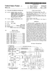
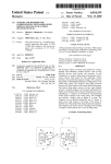
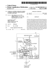
US005960065A
Ulllted States Patent [19]
[11] Patent Number:
Beck et al.
[45]
Date of Patent:
5,960,065
*Sep. 28, 1999
[54]
TWO-LINE TELEPHONE CONTROLLER
WITH HOLD FEATURE
5,131,026
5,142,567
5,151,972
7/1992 Park ...................................... .. 379/100
8/1992 Watanabe
.. 379/100
9/1992 Lorenz~ et al. ..
379/93
[75]
Inventors: Gregory
Douglas LF. Palmer,
Beck, Laguna
P9091111
Hills;
Rénch;
5j40sj525
4/1995 Eldering
2:251;
.... .. "
James A. Fontana, Mission V1610;
5,590,185
.. 379/162
12/1996 Sandler et al. ........................ .. 379/163
Richard D. Ray, Mountain View, all of
Calif
FOREIGN PATENT DOCUMENTS
_
_
_
_
282628
Assignee: Canon Kabushlkl Kalsha, TOkyO,
[*]
NOIiCeI
2650141
2249240
1/1991
4/1992
France .
United Kingdom .
This patent issued on a continued pros-
9004299
4/1990
WIPO .
154(a)(2).
Continuation-in-part of application No. 08/160,824, Dec. 3,
Field Of Search ....................... .. 375/222; 379/9001,
379/93.05, 93.07, 156, 162, 163, 423, 100
[56]
3,771,134
3,879,579
3,920,928
[57]
ABSTRACT
In a tWo-line telephone controller Which includes a line
select sWitch Which operates complementarily to a force
busy relay that alloWs an unselected telephone line to be
forced to a busy state, a method for using the force busy
References Cited
relay also to place an active line on hold. The method
includes detecting an incoming call on an inactive line,
U.S. PATENT DOCUMENTS
sWitching the line select sWitch to the inactive line, receiving
379/93.07
an instruction to place the active line on hold, and respond
ing to the hold instruction by closing an off-hook relay so as
to connect the force busy sWitch across the active telephone
line, opening a ?rst handset select sWitch for the active
telephone line, and closing a second handset select sWitch so
as to select the incoming call on the ringing line. Because the
force busy sWitch is connected across the formerly-active
Streck ..... ..
379/100
telephone line, loop current is maintained, thereby placing
5/1990 Shung ..... ..
379/100
and maintaining the formerly-active call on hold.
11/1973
4/1975
11/1975
Huettner et al. ...................... .. 395/325
Fretwell et al. ................... .. 379/93.05
Lye .................. ..
379/163
4,578,537
3/1986 Faggin et al. .
379/93
4,628,153
12/1986 Daly ............ ..
379/163
4,640,989
2/1987 Riner et al.
4,825,461
4/1989 Kurita et al. ..
4,852,153
7/1989
4,924,494
9/1991 Weiser et al.
379/90.01
5,048,073
Primary Examiner—Vivian Chang
Assistant Examiner—George Eng
Attorney, Agent, or Firm—FitZpatrick, Cella, Harper &
Scinto
Int. Cl.6
.... .. H04M 11/00; H04M 1/00
US. Cl. ..................... .. 379/93.07; 379/162; 379/163;
379/10012
[58]
“4LS User Manual”, Version 1.0, BICOM Computer and
Communications Systems, pp. 1—5.
“RC96ACL/RC144ACL Modem Designer’s Guide”, Rock
“DAA Designers Guide”, Duane Marcroft, Sep. 1989.
1993, Pat. NO. 5,515,423.
[51]
[52]
OTHER PUBLICATIONS
lished 1993.
Mar. 14, 1996
Related US. Application Data
[63]
'
Well International Digital Communications Division, pub
[21] Appl. No.: 08/615,777
Filed:
European Pat. Off. .
European Pat~
Japan
ecution application ?led under 37 CFR
1.53(d), and is subject to the tWenty year
patent term provisions of 35 U.S.C.
[22]
4/1983
666680
5,056,132
10/1991 Coleman et al. .
5,056,133
10/1991
379/94
379/95
12 Claims, 13 Drawing Sheets
Iida ......................................... .. 379/98
COMPUTER BUS
1
|
'
CONTROLLER
LOOP
CURRENT
SENSE
‘
CONTROL
LOGIC
MODEM
DATA PUMP
1
numo OUT
1
2/4
CONVERTER
n
65
78
BIT U
RING
DEFECT 1
FIING DEFECT
67
OR
W
BIT
|
100
U.S. Patent
Sep.28, 1999
Sheet 3 0f 13
MZOInEP
5,960,065
a
_
q-.
_2Q0m59<3o2m0
“
n
g
k
om
g
F"_wzo m jmh
““JoEzo nn0604
1mEwaz<
_3mFwzE§>oN"<EwmzAo=nm<j?9V
m
mz:QQ)
_
n
9“
n
f9\l
M_wmzovlmowi
ImMPjDQEO
,N/
J2
E
I._
_
U.S. Patent
Sep.28, 1999
Sheet 5 0f 13
XEO2IH3EO XmOwIzHEj
5,960,065
P0Emw2O%Z:<I
m.6_n
35m
U.S. Patent
Sep.28, 1999
Sheet 6 0f 13
5,960,065
S601
CONNECT TELEPHONE HANDSET TO ACTIVE LINE
S602
DETECT
INCOMING CALL ON
INACTIVE TELEPHONE
LINE
9
S603
CLOSE LINE SELECT SWITCH BETWEEN
FAX/MODEM/VOICE/ CHIPSET AND RINGING LINE
I
8604
CONNECT FORCE BUSY RELAY TO ACTIVE LINE
/
S605
HOLD
/
INSTRUCTIONS
FOR ACTIVE
LINE
9
CLOSE MODEM
j
YES
OFFHOOK SWITCH TO
HINGING LINE
S608
CLOSE MODEM OFFHOOK
SWITCH TO ACTIVE LINE
8607
l
EQU|g\(/|)EMNPTU£1E-?ENDS
DISCONNECT TELEPHONE
To |NCOM|NG CALL
HANDSET FROM ACTIVE LINE
l
8609
S610
CONNECT TELEPHONE
HANDSET TO RINGING LINE
l
USER A'I‘I'ENDS TO INCOMING
CALL ON TELEPHONE HANDSET
FIG. 6
S611
H)
U.S. Patent
Sep. 28, 1999
5,960,065
Sheet 7 0f 13
S701
INCOMING
RING DETECTED
'2
IDLE
NO
LOOP
$703
MOVE MODEM TO LINE 1 MOVE
HANDSET TO LINE 1
I
ANSWER CALL WITH MODEM
S704
(MODEM CLOSES OFFHOOK
RELAY-LINE 1)
S705
DETECTED
?
S706
M ODEM ALLOWS USER-HANDSET TO TAKE OVER
CALL (MODEM OPENS OFFHOOK RELAY-LINE 1)
I
S707
INCOMING RING DETECTED
S708
YES
FIG. 7A
MOVE MODEM TO SELECT LINE 2
FIG. 75
FIG. 7C
FIG. 7
FIG. 7A
S709
U.S. Patent
Sep. 28, 1999
5,960,065
Sheet 8 0f 13
S710
CLOSE OFFHOOK RELAY ON LINE 1
(UNSELECTED LINE) T0 MAINTAIN LOOP
CURRENT, WHEN HANDSET SELECTION MOVES
I
USER HANGS UP HANDSET
87“
(MAKING lT AVAILABLE FOR
INCOMING CALL)
l
S712
MOVE HANDSET TO LINE 2
J
i
8713
MODEM ANSWERS CALL ON
LINE 2 (MODEM CLOSES
OFFHOOK RELAY‘LINE 2)
S714
HANDSET
PICKUP
DETECTED
'?
S715
MODEM ALLOWS USER-HANDSET TO
COMPLETE CALL USER TALKS ON HANDSET
(CLOSING HANDSET OFFHOOK RELAY) (MODEM
OPENS OFFHOOK RELAY-LINE 2)
I
8716
CALL ON LINE 2 COMPLETES (USER
HANGS UP HANDSET) (OPENS
HANDSET OFFHOOK RELAY)
I
MOVE HANDSET TO SELECT LINE 1
FIG. 7B
S717
J
U.S. Patent
Sep.28, 1999
Sheet 9 0f 13
5,960,065
S718
USER PICKS UP HANDSET ON LINE 1 (TO
FINISH VOICE CALL ON LINE 1)
S719
OPEN MODEM OFFHOOK RELAY-LINE 1 (LINE 1 IS
THE MODEM'S UNSELECTED LINE)
l
S720
USER COMPLETES CALL BY HANGING UP (OPENS
HANDSET OFFHOOK RELAY)
S721
GO BACK TO IDLE LOOP (STEP 8701)
FIG. 7C
U.S. Patent
Sep. 28, 1999
5,960,065
Sheet 11 0f 13
S901
K
CONNECT TELEPHONE HANDSET TO ACTIVE
TELEPHONE LINE
S902
IDLE
LOOP
DETECT
INCOMING CALL
ON INACTIVE
TELEPHONE LINE
S903
K
CLOSE LINE SELECT SWITCH BETWEEN
FAX/MODEMNOICE CHIPSET AND RINGING LINE
S904
l
CONNECT FORCE BUSY RELAY TO ACTIVE LINE
S905
HOLD
INSTRUCTIONS
FOR ACTIVE LINE
?
CLOSE MODEM
j
YES
OFFHOOK SWITCH
TO RINGING LINE
8908
CLOSE LINE SELECT
SWITCH BETWEEN
FAX/MODEMNOICE
CHIPSET AND ACTIVE LINE
S907
COMPUTER
EQUIPMENT
A‘ITENDS TO
INCOMING CALL
H G 9A
FIG. 9A
'
FIG. 98
FIG. 9c
FIG. 9
U.S. Patent
Sep. 28, 1999
5,960,065
Sheet 12 0f 13
S909
CONNECT FORCE BUSY RELAY
TO RINGING LINE
I9
I
CLOSE MODEM OFFHOOK SWITCH I_/
TO ACTIVE LINE
I
S911
MODEM IS PUT IN VOICE MODE, AND
AUDIO IN IS PLAYED ON ACTIVE LINE
I
8912
DISCONNECT TELEPHONE
HANDSET FROM ACTIVE LINE
I
S913
CONNECT TELEPHONE HANDSET
TO RINGING LINE
'
USER A'ITI'ENDS TO INCOMING CALL
ON TELEPHONE HANDSET
FIG. 9B
S914
U.S. Patent
Sep.28, 1999
Sheet 13 0f 13
5,960,065
S915
USER COMPLETES INCOMING VOICE
CALL ON TELEPHONE HANDSET
S916
MOVE HANDSET TO ACTIVE LINE
S917
STOP PLAYING AUDIO IN TO
ACTIVE LINE
S918
USEFI CONTINUES VOICE CALL ON
ACTIVE LINE WITH TELEPHONE
HANDSET
S919
GO TO IDLE LOOP (STEP S902)
FIG. 9C
5,960,065
1
2
TWO-LINE TELEPHONE CONTROLLER
WITH HOLD FEATURE
handset select sWitches, are controlled so as to place and
maintain a currently active one of the multiple telephone
RELATED APPLICATIONS
lines in a hold state. Speci?cally, a ?rst handset select sWitch
is closed so as to connect the telephone handset interface to
a ?rst telephone line Which is currently active. An incoming
This application is a continuation-in-part of prior US.
application No. 08/160,824, ?led Dec. 3, 1993, entitled
“TWo-Line Telephone Controller”, Which issued as US. Pat.
No. 5,515,423.
BACKGROUND
call is detected on a second telephone line, and the line select
sWitch is sWitched so as to ready the computeriZed telephone
communication equipment for connection to the second
10
telephone line, thereby sWitching the force busy sWitch so as
to ready others of the multiple telephone lines for connection
to the force busy means. An instruction to place the ?rst
1. Field of the Invention
telephone line on hold is then received, such as from a user
operating a graphical user interface on the computer. In
response to the hold instruction, an off-hook relay for the
The present invention concerns a method for operating a
tWo-line telephone controller so as to obtain a hold feature
by Which a currently active one of at least tWo telephone
lines is placed and maintained in a hold state.
2. Description of the Related Art
Application No. 08/160,824 describes a computer con
trollable telephone control board Which interfaces betWeen a
computer and multiple telephone lines so as to provide the
computer With control over multiple telephone lines. In the
embodiment described in application No. 08/160,824, tWo
telephone lines are controlled, With the board alloWing the
telephone lines to be connected to the computer (via a
faX/modem/voice chipset, so as to permit computer
15
?rst telephone line is closed, thereby connecting the force
busy means across the ?rst telephone line, the ?rst handset
select sWitch is opened, and a second handset select sWitch
is closed so as to connect the telephone handset interface to
20
the second telephone line. Because the force busy means is
connected across the ?rst telephone line, loop current is
maintained and the ?rst telephone line is maintained in a
hold state.
This brief summary has been provided so that the nature
of the invention may be understood quickly. A more com
25
controlled faX and modem data transfers, as Well as to permit
plete understanding of the invention can be obtained by
reference to the folloWing detailed description of the pre
ordinary voice communication using a microphone and
ferred embodiment thereof in connection With the attached
draWings.
speakers connected to the computer), or to be connected to
a conventional telephone handset (via a telephone handset
interface so as to permit ordinary voice communication over
30
FIG. 1 is a perspective vieW of the outWard appearance of
an apparatus illustrative of a communication arrangement
the handset).
The telephone control board of application No. 08/160,
for personal computing equipment in Which the present
824 includes a “force busy” relay Which causes an unused
telephone line to appear busy When the active telephone line
35
is connected to the computer, such as for modem transfers.
As described in application No. 08/ 160,824, this “force
busy” feature is advantageous, especially When the com
puter is not attended by the user, since the caller Will be
confronted by a busy signal rather than a ringing signal that
is never ansWered. When confronted by a busy signal, most
callers Will simply call back later; in fact, most conventional
invention is incorporated.
FIG. 2 is a block diagram of the FIG. 1 apparatus.
FIG. 3 is a functional block diagram of a ?rst embodiment
of a communication board for use With the invention.
40
facsimile machines have an automatic re-dial feature Which
calls back later automatically.
SUMMARY OF THE INVENTION
BRIEF DESCRIPTION OF THE DRAWINGS
45
FIG. 4 is a schematic circuit diagram of the communica
tion board shoWn in FIG. 3.
FIG. 5 is a schematic circuit diagram of the control logic
shoWn in FIG. 4.
FIG. 6 is a How diagram shoWing operation of the
communication board to place a currently active telephone
line on hold.
FIG. 7 is a How diagram shoWing a representative
eXample of the hold feature, in Which an active voice call on
line 1 is put on hold to permit ansWering an incoming call
The present invention obtains a hold feature in a tele
phone control board Which, like that in application No.
08/160,824, includes a force busy relay. According to the
invention, the same “force busy” relay by Which an unused
telephone line is forced busy is also used to place an active
on line 2.
FIG. 8 is a schematic circuit diagram of a second embodi
call on hold.
ment of a communication board for use With the invention.
Thus, one aspect the invention is a method for operating
a telephone control board having a line select sWitch Which
FIG. 9 is a How diagram shoWing operations to put a
currently active telephone line on hold.
connects to computeriZed telephone communication equip
55
ment to a selected one of multiple telephone lines through
off-hook relays respectively provided for each telephone
line, a force busy sWitch Which operates complementarily to
the line select sWitch and by Which force busy means is
connectable across unselected ones of the multiple telephone
lines through the respective off-hook relays so as to maintain
loop current in the unselected ones of the multiple telephone
FIG. 1 is a vieW shoWing the outWard appearance of a
representative embodiment of the invention. ShoWn in FIG.
60
each of the multiple telephone lines so as to connect a
telephone lines. According to the invention, the line select
sWitch, the force busy sWitch, the off-hook relays, and the
1 is computing equipment 10 such as an IBM PC or
PC-compatible computer having an operating system such
lines, and handset select sWitches respectively provided for
telephone handset interface to any one of the multiple
DETAILED DESCRIPTION OF THE
PREFERRED EMBODIMENT
65
as a Microsoft WindoWs operating system. The computing
equipment 10 is provided With a display screen 11 such as
a color monitor, a speaker 12 and a microphone 13. Com
puting equipment 10 further includes a mass storage device
such as a computer disk drive 14 for storing data ?les such
as bitmap image data ?les, teXt data ?les, sound (e.g., PCM
5,960,065
3
4
or pulse code modulation) data ?les, animation data ?les and
digital motion video data ?les, in compressed or uncom
invariant functions such as start-up programs or BIOS
programs. Main memory 42 Which includes random access
pressed format; and for storing application program ?les
memory (RAM) provides CPU 30 With memory storage
such as a multimedia message management program that
both for data and application programs, as required. In
can send and receive the aforementioned types of data ?les,
or other information processing program ?les Which contain
particular, When executing stored program instruction
stored program instruction steps by Which computing equip
programs, CPU 30 normally loads those instruction
sequences from disk 14 (or other program storage media) to
sequences such as multimedia message management
ment 10 manipulates data ?les, presents data in those ?les to
an operator via display screen 11 or speaker 12, or transmits
data via telephone lines or netWork interfaces, or the like.
10
Keyboard 15 is connected to computing equipment 10 to
permit input of teXt data and to permit operator selection and
manipulation of objects displayed on display screen 11.
Likewise, pointing device 16 such as a mouse or the like is
connected to permit selection and manipulation of objects
15
main memory 42 and eXecutes those stored program instruc
tion sequences out of the main memory.
A communication board 40 Which includes a data com
munication device is connected to computer bus 31 so as to
provide computing equipment 10 With access to and control
over multiple telephone lines and an ordinary telephone
handset. The communication board device on 40 preferably
and graphical user interfaces on the display screen. Scanner
includes a combined faX/modem/voice chipset such as the
18 scans documents or other images and provides bitmap
type described in the RC96ACL/RC144ACL Modem
Designer’s Guide, RockWell International Digital Commu
images of those documents to computing equipment 10.
NetWork interface line 22 connects computing equipment 10
to an unshoWn local area netWork, and printer 24 is provided
nications Division, published 1993, the contents of Which
20
for outputting information processed by computing equip
ment 10.
An unshoWn communication board, Which is described in
voice communication capability for digitiZing incoming
considerable detail beloW, connects computing equipment
voice communications and storing the digitiZed voice in a
computer ?le, and/or converting a digitiZed voice in com
puter ?les into analog form for play out over voice telephone
lines.
10 to an ordinary telephone handset 19 as Well as to multiple
telephone lines, here tWo telephone lines 20 and 21.
In accordance With operator instructions, stored applica
tion programs are activated and permit processing and
manipulation of data. For eXample, any of a variety of
30
application programs such as a multimedia message man
editing program, spreadsheet programs, and similar infor
mation processing programs, may be provided for operator
activated to permit an operator to create, vieW, manipulate
and print documents, and to send or receive documents via
a communication board and one of the multiple telephone
lines. LikeWise, a multimedia message management pro
gram may be activated to permit an operator to create,
manipulate and vieW multimedia documents Which contain
a variety of objects such as teXt objects, bitmap objects,
The communication board 40 further includes a data
access arrangement (DAA) Which includes a line select
sWitch for selecting any one of multiple telephone lines for
connection to the faX/modem/voice chipset. The DAA fur
ther includes the capability for connecting to external
agement program, a Word processing program, an image
selection and use. Thus, a Word processing program may be
are incorporated herein by reference. Such a faX/modem/
voice chipset provides a facsimile modem for automatic
facsimile transmission and reception, a data modem for
automatic data transmission and reception and a digital
speaker 12 or microphone 13 as Well as for connecting to
35
ordinary voice telephone handset 19.
[First Embodiment]
FIG. 3 is a functional block diagram of a ?rst embodiment
of communication board 40. As shoWn in FIG. 3, commu
nication board 40 includes a communication device such as
40
the aforementioned faX/modem/voice chipset 41, and a %
converter 42. The % converter 42 converts a four-Wire signal
from the faX/modem/voice chipset 41 into a tWo-Wire signal
for connection to ordinary voice telephone lines. The tWo
computer graphic objects, sound objects and motion video
objects, and to send and to receive such multimedia docu
Wire signal from % converter 42 is fed to data access
ments via the communication board on one of the multiple 45
arrangement (DAA) 44. The data access arrangement, under
telephone lines. The multimedia message management pro
gram may also be provided With telephone handset control
capabilities With Which an operator, through manipulation
control via control logic 45 from chipset 41 and computing
equipment 10, sWitchably connects one of multiple tele
phone lines, such as telephone lines 20 and 21, to the chipset
and use of a computeriZed address list, may instruct the
computer to cause a selected telephone line to go off-hook,
a selected telephone number to be dialed, and indicate to the
operator that the called party has ansWered. Incoming calls
may also be handled by the computer, and a telephone usage
log may be maintained.
FIG. 2 is a detailed block diagram shoWing the internal
construction of computing equipment 10. As shoWn in FIG.
via the % converter 42. Additionally, DAA 44 includes
handset sWitches for each telephone line for sWitchably
connecting, under control via control logic 45 from chipset
41 and computing equipment 10, one of the telephone lines
55
to telephone handset 19.
Preferably, and as depicted in FIG. 3, the communication
board 40 is arranged on a single, multiple-layer, circuit
board provided With an edge connector 43 for connection to
2, computing equipment 10 includes central processing unit
computer bus 31, as Well as suitable RJ-14 connectors for
(CPU) 30 such as an 80386 or a reduced instruction set
connection to handset 19 and telephone lines 20 and 21. The
single-board construction alloWs board 40 to be inserted into
computer (RISC) interfaced to computer bus 31. Also inter
faced to computer bus 31 is scanner interface 32 for inter
60
facing to scanner 18, display interface 34 for interfacing to
display 11, netWork interface 35 for interfacing to netWork
line 22, printer interface 37 for interfacing to printer 24,
keyboard interface 36 for interfacing to keyboard 15, and
pointing interface 38 for interfacing to pointing device 16.
Read only memory (ROM) 41 interfaces With computer
bus 31 so as to provide CPU 30 With specialiZed and
the housing of conventional PC-type computing equipment.
Of course, While a single-board construction is preferred, the
communication board 40 may, in fact, be comprised by
multiple interconnected circuit boards.
65
FIG. 4 is a schematic diagram illustrating the communi
cation board of FIG. 3. As shoWn in FIG. 4, the faX/modem/
voice chipset 41 includes a modem controller 50 connected
via modem bus 51 to a modem data pump 52. Also con
5,960,065
5
6
nected to modem bus 51 are EPROM 54 and local RAM 55
Which serve as memories for programming and processing
If a loop current is detected, then loop current detect
device 74 sends a loop current detect (LCD) signal to
modem controller 50 and to AND gate 57.
Telephone handset 19 is operable in either a manual mode
or a computer-controlled mode. In the manual mode, When
telephone handset 19 is lifted, it is connected to one of
telephone lines 20 or 21 in accordance With the setting of
handset sWitches 70 and 71. Manual outgoing dialing and
operations of the modem and Which may have a capacity of
128K bytes each. An audio path in chipset 41 includes an
audio output interface portion 52a of the modem data pump
Which is connectable to speaker 12, as Well as an audio-in
sWitch 56 Which permits connection to microphone 13 so as
to provide the modem data pump 52 With an audio input
interface under control of AND device 57.
voice communication may then occur.
In operation, modem controller 50, via commands and
data sent from computing equipment 10 on computer bus 31,
For computer-controlled outgoing dialing, computing
equipment 10 ?rst causes modem controller 50 to select the
desired lines 20 or 21 via line select sWitch 61. The appro
priate one of off-hook sWitches 63 or 64 is then closed and
the modem controller 50 causes modem data pump 52 to
sets its state and the state of the modem data pump to one of
audio in, audio out, fax modem, data modem or voice. Then,
modem controller 50 causes modem data pump 52 either to
output audio signals to speaker 12, to input audio signals
from microphone 13, or to transmit or receive faX, modem
15
initiate telephone dialing such as DTMF or pulse dialing
or voice information via a four-Wire connection to % con
over the selected line. Handset sWitches 70 and 71 are set in
verter 42.
% converter 42 converts the four-Wire connection from
modem data pump 52 into a tWo-Wire connection to data
accordance With the selected line, and the user is then
instructed to lift the handset from telephone handset 19. As
soon as loop current detect (LCD) signal is detected, indi
access arrangement (DAA) 44.
cating the presence of loop current betWeen the tip and ring
Wires of telephone handset 19, modem controller 50 discon
As further shoWn in FIG. 4, DAA 44 includes a trans
former 60 for impedance-matching the tWo-Wire signal from
nects both of off-hook sWitches 63 and 64 to permit the user
to conduct ordinary voice communication. If the user does
% converter 42 to the impedance of an ordinary voice
telephone line. A line select sWitch 61 is provided to select
one of multiple telephone lines, here tWo lines designated 20
and 21, respectively. The line selector sWitch 61 is operated
25
not lift the handset from telephone handset 19, then the LCD
signal Will not be detected, and When the called party
ansWers, the faX/modem/voice chipset 41 Will operate in
under control from modem control logic 45 so as to select
either of the tWo lines.
accordance With its ordinary programming.
For incoming calls, ring detect circuits 65 and 66 detect
Each of the telephone lines has connected in series
thereWith a modem off-hook sWitch, speci?cally modem
off-hook sWitch 63 for line 20 and 64 for line 21. Under
control from control logic 45, each of those sWitches may be
that one of the telephone lines carries a ringing signal, and
signals that detection to modem controller 50 via AND gate
activated so as to cause the selected line to go off-hook With
respect to faX/modem/voice chipset 41 When line select
sWitch 61 has selected that line.
35
Ring detect circuits 65 and 66 detect ringing signals on
each of lines 20 and 21, respectively. In response to a ringing
such as tWo rings, the LCD signal is not detected indicating
that the user has not lifted the handset, then control logic 45
causes the ringing line to go off-hook by setting modem
off-hook sWitches 63 or 64, as appropriate. The faX/modem/
voice chipset then operates in accordance With its pre
signal, each ring detect circuit sets a bit in an unshoWn
computer register indicating Which of the lines 20 and 21 is
ringing. In addition, the ring detect signals are ORed
together via OR gate 67 and the resultant ORed signal sent
to AND gate 68. The resultant ring detect signal is sent to
modem controller 50 Whereby modem controller 50 can
recogniZe When one of line 20 and 21 is ringing. In this
regard, AND gate 68 is provided so that a ring detect signal
is blocked When modem controller 50 is engaged in modem
operations. Thus, When either of lines 20 or 21 is off-hook
via off-hook sWitches 63 and 64, an off hook signal OH is
generated by modem controller 50. The OH signal blocks a
ring detect signal in the event that either line is off-hook,
68. Computing equipment 10 reads its unshoWn computer
register to determine Which line is ringing, and control logic
45 then sWitches line select sWitch 61 to the appropriate line.
In addition, control logic 45 sets handset select sWitches 70
or 71 to the ringing line. If, after a predetermined period
programmed instructions. Ordinarily, computing equipment
10 is programmed such that if the LCD signal is detected by
the user lifting the handset from telephone handset 19,
45
off-hook sWitches 63 and 64 are both disconnected leaving
the user in ordinary voice communication With the calling
party.
As mentioned above, if the faX/modem/voice chipset 41 is
engaged in data communications via one of telephone lines
20 or 21, then the ring detect signal to chipset 41 is blocked
via AND gate 68 because of the existence of the OH signal.
thereby preventing modem controller 50 from being inter
Because the ring detect signal is blocked, chipset 41 Will not
rupted from its modem operations When one of the lines is
be interrupted in its faX or modem or voice communications.
At the same time, because handset sWitches 70 and 71 are
off-hook and engaged in modem operations.
ordinarily set to the unused telephone line, any incoming
The DAA further includes for each telephone line a
handset sWitch 70 and 71 for connecting lines 20 and 21,
respectively, to telephone handset 19 via handset interface
100. The handset sWitches 70 and 71 are operated under
control of control logic 45 via “handset to line 1” and
“handset to line 2” control signals. These signals are set such
that only one telephone line is connected to telephone
handset 19 at any one time, and preferably they are set such
that if data communications are being conducted on one
telephone line, the handset is not connected to that line.
Aloop current detect device 74 is positioned betWeen the
55
calls on that line Will activate the ringer in telephone handset
19 thus alerting the user aurally to the presence of such a
ringing signal.
DAA 44 further includes a voice relay 75 for setting DAA
44 to a voice local mode. In the voice local mode, voice relay
75 is activated to disconnect DAA 44 from all telephone
lines and to connect the DAA to a V+ voltage supply. In the
voice local mode, the communication board can be used to
play out sound over either speaker 12 or the speaker in
telephone handset 19, or to record sound either from micro
ring and tip Wires of telephone handset 19 so as to sense a 65 phone 13 or from the microphone in telephone handset 19.
loop current When the handset in telephone handset 19 is
lifted.
More speci?cally, When the voice-local mode is desired,
a voice local mode signal is sent from modem controller 50
5,960,065
7
8
to voice relay 75 thereby disconnecting DAA 44 from all
telephone lines and reconnecting it to V". Thereafter, sound
TABLE II
from modem data pump 52 may be heard over speaker 12 or
I/O READ CONFIGURATION REGISTER +2 (BASE +2)
the speaker in telephone handset 19. At the same time, sound
may be recorded from either microphone 13 or from the
microphone in telephone handset 19. In this regard, using
loop current detect signal LCD, AND gate 57 Will block
recordal of sound from microphone 13 in the case that the
handset has been lifted from the telephone handset 19
I— — line 1 ringing
—
— line 2 ringing
10
thereby preventing sound from being recorded from both the
telephone handset and microphone 13 at the same time.
Relay 76 operates to force a busy signal on unselected
ones of the multiple telephone lines. Thus, as shoWn in FIG.
15
FIG. 5 is a detailed schematic diagram of control logic 45.
As shoWn in FIG. 5, control logic 45 accepts the off-hook
signal OH from modem controller 50 and combines it, using
OR and AND gate logic circuitry, With control bits 2, 3 and
4 from “BASE +0” register so as to obtain the line select
4, relay 76 is connected to each of the telephone lines
signal for line select sWitch 61, the modem off-hook signals
for off-hook sWitches 63 and 64, and the handset signals for
betWeen the line select sWitch 61 and off-hook sWitches 63
and 64. The relay 76 is actuated through inverter 77 by the
line select signal from control logic 45, and thus operates
handset sWitches 70 and 71. The logic circuitry implements
the folloWing boolean equations:
complementarily to the line select sWitch so as to connect the
unused telephone line to resistor R1. Force busy is obtained
by closing the off-hook sWitch for the unselected telephone
lines, thereby connecting the telephone line to resistor R1
LINE sELEcT=BIr4
OFFHOOK LINE 1=(oII-W)+(BIT2-BIT4)
25
Which has a value, e.g., 100 Q, loW enough to indicate to the
OFFHOOK LINE 2=(oII-BIr4)+(BIr2-W)
telephone central office that the unused telephone line is
busy. As an operational example, if line select sWitch 61 is
HANDSET TO LINE hm
set to select line #1, then because of inverter 77 force busy
relay 76 connects resistor R1 to line #2. To force busy on line
HANDSET TO LINE 2=BIT3
More simply, as shoWn in Table I above, bit 3 controls
handset sWitches 70 and 71, and bit 4 controls line select
sWitch 61. As for off-hook sWitches 63 and 64, off-hook
sWitch 63 (corresponding to line #1) is closed if modem
#2, control logic 45 causes modem off-hook sWitch 64,
corresponding to line #2, to close. The telephone central
office “sees” resistor R1 and interprets that resistor as an
indication that line #2 is busy. Thus, callers calling into line
#2 Will receive a busy signal even though no physical
35
telephone equipment (e.g., telephone handset 19 or chipset
41) is connected to line #2.
controller 50 signals to go off-hook by raising off-hook
signal OH and if line #1 is selected (i.e., bit 4=0), and also
if line #2 is selected (i.e., bit 4=1) and bit 2 is set to force
busy on unselected lines. LikeWise, off-hook sWitch 64
(corresponding to line #2) is closed if modem controller 50
signals to go off-hook by raising off-hook signal OH and if
line #2 is selected (i.e., bit 4=1), and also if line #1 is
selected (i.e., bit 4=0) and bit 2 is set to force busy on
As mentioned above, control of the communication board
is accomplished through bit settings in an unshoWn com
puter register. The folloWing tables I and II shoW those bit
unselected lines.
In operation, and in response to an incoming call on any
settings:
45
TABLE I
of the phone lines, the system preferentially activates the
data communication device, here the modem/faX/voice
chipset, While activating the handset When the communica
tion device is busy. In addition, the communication device is
protected from unWanted interruptions While alloWing a user
I/O WRITE TO CONFIGURATION REGISTER (BASE +0)
manually to respond to incoming phones via the telephone
handset 19. It is also possible to block incoming calls by
forcing unused lines to a busy state. Such functionality is
preferred in an unattended state Where a user is unable to
respond manually to incoming telephone calls While the
— comm port setting
55
— — 0: don't force busy on
unselected lines
1: force busy on
unselected lines
communication device is in use. The reason Why such
functionality is desirable is because a caller calling an
unattended station may become aggravated at an unan
— O: handset to line #1
: handset to line #2
— 0: line select to line #1
1: line select to line #2
— IRQ setting
65
sWered telephone line and Will be less aggravated if a busy
signal is instead obtained. In addition, automatic message
dialing systems, such as remote facsimile machines, ordi
narily have re-try modes for message dialing, and those
re-try modes are activated only if a busy signal is obtained.
Of course, it is possible to replace telephone handset 19 With
an ordinary voice telephone ansWering machine to accom
modate unattended operation.
In general, after detecting a ring detect signal, computing
equipment 10 performs an I/O read of its “BASE +2”
5,960,065
10
register to determine Which line is ringing. As shown in the
above Table II, if bit 0 is set, then line 1 is ringing While if
bit 1 is set then line 2 is ringing. After determining Which
line is ringing, the handset is moved to the ringing line by
setting the appropriate one of handset sWitches 70 and 71.
Then, by performing an I/O Write to bit 4 of the “BASE +0”
register, as shoWn in the above Table I, line select sWitch 61
is set to the ringing line, and by performing an I/O Write to
the BASE +0 register, the appropriate one of modem off
hook sWitches 63 and 64 is set to the ringing line. The call
is then ansWered via chipset 41 or by the user lifting the
handset of telephone handset 19, Which action is detected by
possible for computing equipment 10 to alloW the user to
“break into” the phone call by chipset 41. In this instance,
computing equipment 10 forces handset sWitches 70 and 71
into their appropriate state and alloWs the user to break into
the line by lifting the handset.
In summary, for the above situation, the “preferential
order” for selecting one of the telephone lines for connection
to the data communication device is line 1 folloWed by line
2. Accordingly, the “reverse preferential order” for selecting
10
[Hold Feature]
modem controller 50 through the loop current detect (LCD)
FIG. 6 is a How diagram shoWing process steps by Which
the same force busy relay 76 that is used to force a busy
signal, as described hereinabove.
Speci?c operations taking into consideration the current
one of the telephone lines for connection to the telephone
handset is line 2 folloWed by line 1.
15 signal on an unused line can also be used to implement a
state of the telephone handset and the faX/modem/voice
hold feature. Brie?y, according to FIG. 6, in a case Where
chipset are described as folloWs:
telephone handset 19 is currently being used for voice
[Incoming Call On Line 1]
communication on an active telephone line and an incoming
call is detected on an inactive telephone line, the active
If neither the faX/modem/voice chipset 41 nor telephone
handset 19 is in use, then computing equipment 10 connects
both chipset 41 and telephone handset 19 to line 1 as
described hereinabove.
If chipset 42 is not in use but line 2 is in use by telephone
telephone line can be put on hold by (1) sWitching the line
select sWitch to the ringing line so as to ready the comput
eriZed telephone equipment for connection to the ringing
line, thereby sWitching the force busy sWitch to the active
line in vieW of the complementary operation of the line
handset 19, then computing equipment 10 connects chipset
41 to line 1.
25
If chipset 41 is currently conducting communications on
responding to a hold instruction by closing the modem
off-hook relay (63 or 64) corresponding to the active tele
phone line, thereby connecting the force busy means across
line 2, and telephone handset 19 is not in use, then com
puting equipment 10 moves telephone handset 19 to line 1
the active telephone line, (3) disconnecting the telephone
handset from the active telephone line, and (4) connecting
for attended voice operation. Alternatively, by setting bit 2
of “BASE +0”, Which causes unselected lines to appear
“busy” to the telephone central of?ce, it is possible to force
busy on line 1 for unattended operation.
If both the modem and the phone handset are conducting
communication on line 2, then line 1 is forced busy by
setting bit 2, as described above.
the telephone handset to the ringing line. Because the force
busy resistor 78 is noW connected across the formerly active
35
[Incoming Call On Line 2]
telephone line, even though the telephone handset has been
disconnected from that formally active telephone line, loop
current is maintained thereby keeping the formerly active
telephone line on hold While the user attends to the incoming
call on the ringing telephone line via the telephone handset.
Referring speci?cally to the process steps shoWn in FIG.
If neither chipset 41 and telephone handset 19 are in use,
computing equipment 10 connects both chipset 41 and
telephone handset 19 to line 2.
If chipset 41 is conducting communication on line 1, and
telephone handset 19 is not in use, then computing equip
ment 10 connects telephone handset to line 2 for attended
operation. Alternatively, it is possible to force busy on line
6, since it is assumed that a user is conducting a voice
telephone communication With a currently active telephone
2 by setting bit 2 of “BASE +0” register for unattended
operation.
select sWitch and the force busy relay (via inverter 77), (2)
45
If chipset 41 is not in use but telephone handset 19 is in
use With line 1, then computing equipment 10 connects
chipset 41 to line 2.
If both chipset 41 and telephone handset 19 are conduct
ing communication on line 1, then line 2 is forced busy by
setting bit 2 of “BASE +0” register.
line, step S601 shoWs the telephone handset connected to an
active telephone line, using an appropriate one of handset
select sWitches 70 or 71 in accordance With Which of line 20
or 21 is the active telephone line. Until an incoming call is
detected on an inactive telephone line, How remains at step
S602. It should, of course, be realiZed that the process steps
shoWn in FIG. 6 are directed to the hold feature only, and
that other processes including communication processes are
ongoing and do not result in the apparent “in?nite loop”
shoWn at step S602.
When an incoming telephone call is detected on an
[Outgoing Calls From Chipset 41]
inactive telephone line, How advances to step S603 in Which
For an outgoing call by chipset 41, then computing
equipment 10 preferentially connects chipset 41 to the ?rst
line select sWitch 61 is operated so as to ready the comput
eriZed telephone equipment to ansWer the incoming call on
available line, i.e., ?rst line 1 or if line 1 is in use then to line
55
the ringing line. Speci?cally, line select sWitch 61 is closed
2. Alternatively, it is possible for computing equipment 10 to
override this automatic selection by appropriate Writes to
so as to connect betWeen faX/modem/voice chipset 41 (via %
bits in the “BASE +0” register.
since neither one of modem off-hook sWitches 63 or 64 is
converter 42) and the ringing line. At this point, hoWever,
[Outgoing Calls From Handset 19]
closed, the faX/modem/voice chipset 41 is not actually
For outgoing calls on telephone handset 19, then if neither
telephone line is in use, computing equipment 10 connects
telephone handset 19 in reverse preferential order to that of
connected to the ringing line.
How then advances to step S604 in Which force busy
relay 76 is connected to the active line. This step happens
automatically, in vieW of the complementary relation estab
lished by inverter 77 betWeen line select sWitch 61 and force
chipset 41. Thus, computing equipment 10 ?rst connects
telephone handset to line 2, or if line 2 is in use by chipset
41 then to line 1.
In the event of an outgoing call from the telephone
handset While line 1 or line 2 is in use by chipset 41 it is
65
busy relay 76.
How then advances to step S605 Which determines
Whether an instruction has been received to place the active
5,960,065
11
12
line on hold. The instruction may be received from an
call. Speci?cally, off-hook sWitch 64 is opened so as to
unshoWn interface on telephone handset 19, or may be
disconnect the modem from the incoming call thereby
issued by the user via a graphical user interface on screen 11.
alloWing a user to carry on a voice communication over the
telephone handset.
Whatever its source, if the hold instruction is not issued,
?oW advances to step S606 (for example, after a predeter
mined number of rings) in Which the modem off-hook sWitch
In step S716, When the user completes his call and hangs
up his handset, handset select sWitch 71 is opened and
handset select sWitch 70 is closed thereby alloWing the user
to complete the call on line 1 (step S718). At the same time,
corresponding to the-ringing telephone line is closed, and
thence to step S607 in Which the computer equipment
attends to the incoming call.
On the other hand, if step S605 determines that a hold
instruction has been received, then ?oW advances to step
S608 in Which the modem off-hook sWitch for the active line
is closed. Closing the modem off-hook sWitch for the active
in step S719, modem off-hook relay 63, corresponding to
10
from the again-active line 1. In step S720, the user completes
the call on line 1 and hangs up, Whereupon ?oW advances to
step S721 in Which the computer reverts to its idle loop.
[Second Embodiment]
line causes the force busy resistor 78 to be connected across
the active telephone line. Thereafter, in step S609, the
telephone handset is disconnected from the active telephone
line 1, is opened so as to disconnect force busy resistor 78
15
FIG. 8 is a schematic diagram illustrating a second
embodiment of a communication control board for use With
the invention. Using the communication board of FIG. 8, it
is possible to place a currently active telephone line on hold
line. HoWever, because force busy resistor 78 is noW con
nected across the active line, loop current is maintained in
the active line thereby placing and maintaining the currently
and to play out audio information such as music over the
active telephone line in a hold state. How then advances to
held line, thereby alloWing the held caller to listen to music
step S610 in Which the telephone handset is connected to the
ringing line via the appropriate one of handset sWitches 70
While on hold.
The communication board of FIG. 8 is identical in all
respects With the communication board of FIG. 4, With the
and 71. The user is then free to attend to the incoming call
line 1, and a second telephone call is then received on line
exception of audio in input 102. Imput 102 alloWs fax/
modem/voice chipset 41, While in the voice mode, to mix
pre-recorded audio information through % converter 42 for
playout. Asuitable communication board, Which includes an
2. Thus, in step S701, an incoming ring is detected, and after
determining that the incoming ring is on line 1 (step S702),
application No. 08/341,165 ?led Jan. 19, 1993, “Commu
on telephone handset 19 (step S611).
FIG. 7 shoWs a representative example of the above
25
process in a case Where a ?rst telephone call is received on
audio input such as that illustrated at 202, is described in
nication Control Board With Audio Function”.
Inasmuch as the communication board of FIG. 8 is
?oW advances to step S703 in Which line select sWitch 61 is
moved so as to connect betWeen fax/modem/voice chipset
41 and line 1, and in Which handset select sWitch 70 is closed
so as to also connect telephone handset 19 to line 1. After a
predetermined number of rings in Which the user does not
lift telephone handset 19, modem off-hook sWitch 63 is
35
identical in all respects With FIG. 4, With the exception of
added audio input 202, the processes of FIGS. 6 and 7 are
completely usable With the communication board of FIG. 8,
and they are incorporated here again Without repetition.
closed so that the computeriZed telephone equipment
FIG. 9 is a How diagram shoWing use of the FIG. 8
ansWers the incoming call (step S604). Upon detecting that
communication board to put an active line on hold and to
the user has lifted the telephone handset in step S705, ?oW
advances to step S706 in Which modem off-hook sWitch 63
play out audio information, such as music, on the held line
using audio input 202. Step S901 shoWs a telephone handset
connected to an active telephone line, using an appropriate
is opened so as to alloW the user to take over the active
telephone line using telephone handset 19. In step S707, an
incoming ring is detected on the inactive line, and upon
determining that the ringing line is line 2 (step S708), line
one of handset select sWitches 270 or 271 in accordance With
Which of lines 20 or 21 is the currently active telephone line.
Until an incoming telephone call is detected on an inactive
select sWitch 61 is operated so as to connect betWeen
fax/modem/voice chipset 41 and the ringing line (step
S709). Because of the complementary relation established
by inverter 77, force busy relay 76 connects force busy
45
telephone line, How remains in an idle loop at step S902. It
should, of course, be realiZed that the process steps shoWn
in FIG. 9 are directed to the hold feature only, and that other
processes, including communication processes, are still
resistor 78 across the active line. At this point, hoWever,
since modem off-hook sWitch 64 is not closed, the ringing
line remains unansWered.
Upon receipt of a hold instruction, ?oW advances to step
S710 in Which off-hook relay 63, corresponding to the active
on-going and do not result in the apparent “in?nite loop”
line 1 and not the ringing line 2, is closed so as to connect
puteriZed telephone equipment to ansWer the incoming call
shoWn at step S902.
When an incoming telephone call is detected on an
inactive telephone line, How advances to step S903 in Which
line select sWitch 261 is operated so as to ready the com
on the ringing line. Speci?cally, line select sWitch 261 is
force busy resistor 78 to the active line. The user then hangs
up the handset (step S711) and handset select sWitch 70 for
the active line is opened. HoWever, because force busy
resistor 78 is connected to the active line, loop current is
55
hoWever, since neither one of modem off-hook sWitches 263
maintained.
In step S712, handset select sWitch is closed so as to
connect telephone handset 19 to the ringing line. At the same
or 264 is closed, the fax/modem/voice chipset is not actually
connected to the ringing line.
How then advances to step S904 in Which force busy
relay 276 is connected to the active line. This step happens
automatically, in vieW of the complementary relation estab
lished by inverter 277 betWeen line select sWitch 261 and
time, in step S713, off-hook relay 64, also corresponding to
the ringing line, is closed so as to connect fax/modem/voice
chipset 41 to the ringing line and to permit the computeriZed
telephone equipment to ansWer the incoming call.
In step S714, upon detection that the user has picked up
the handset for telephone handset 19, How advances to step
S715 in Which the modem alloWs the user to complete the
closed so as to connect betWeen fax/modem/voice chipset
241 (via % converter 242) and the ringing line. At this point,
force busy relay 276.
65
How then advances to step S905 Which determines
Whether an instruction has been received to place the active
line on hold. The instruction may be received from an