1
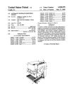
llllllllllllllIlllllllllllllllllllllllllllllllllllllllllllllllllllllllllll
US 0055 1 5423A
Unlted States Patent [191
[11] Patent Number:
Beck et a1.
[45]
[54]
Date of Patent:
TWO-LDZE TELEPHONE CONTROLLER
Puane Maxcm?’ “DIIAA DeIsigners Guides, Sep" 1989'
Douglas L Palmer, Foothill Ranch;
James A_ Fontana, Mission vieI-o;
4LS User Manual , Vers1on 1.0, B1com Computer and
Communications Systems, pp. 1-5.
“RC96ACL/RC144ACL Modem Designer’s Guide”, Rock
Alistair Egan Lake Forest. Richard D_
Ray Laguna lingual. Lisa walker
well International Digital Communications Division, pub
Capistrano Beach, all of Calif.
hshed 1993'
_
_
_
_
Primary Examiner—Jason Chan
[73] Asslgne?: Canon Kabushlkl Kalsha’ Tokyo’
Japan
Attorney, Agent, or Firm—Fitzpatrick, Cella, Harper &
Scinto
[21] Appl. No.: 160,824
[57]
[22]
A computer-controlled
Dec_ 3 1993
’
[51]
[52]
[58]
May 7, 1996
OTHER PUBLICATIONS
[75] Inventors: Gregory F. Beck, Laguna Hills;
Filed:
5,515,423
ABSTRACT
communication
board
which
includes a data access arrangement which functions as an
Int. Cl.6
................... .. H04M 11100
US. Cl. ........... ..
379/93; 379/94; 379/100
Field of Search ................................ .. 379/93, 94, 95,
intermediary between multiple telephone lines, a data com
munication device such as a fax/modem/voice chipset, and
a standard telephone handset. The data access arrangement
379/96, 97, 98, 99, 160, 163, 156; 395/325;
375/222
References Cited
has aline select switch which switchably connects one of the
multiple telephone lines to the data communication device
via a single transformer and associated 2/4 converter. Off
hook switches are provided for each telephone line so that
U'S‘ PATENT DOCUMENTS
phone line to go off-hook. Likewise, n'ng detectors are
[56]
the data communication device can cause the selected tele
3,771,134 11/1973 Huettner et a1. ...................... .. 395/325
3,920,928 11/1975 Lye ................ ..
. 3791163
Provided for each t91912110119 line 80 that the data communi‘
cation device can detect which of those lines is ringing.
4,578,537
4,640,939
3/1986 Faggin etal.
2/1987 Rimf'r 61111
Telephone handset switches may be provided for each
telephone line so that the telephone handset may be swit
4,825,461
379/93
379/94
4/1989 Kunta et a1. ............................ .. 379/93
chably connected to any one of the multiple telephone lines_
151,322,493 1319311) (Sjhung ...... "2.1.1......................... .. 29/91/32
The data access mangemem may be con?gured so that
’ 5 A3
5,131,026
7
379/98
379,100
unused lines appear “busy” to incoming calls, or it may be
.
.
.
.
con?gured m a voice local mode in wh1ch the telephone
. . . .. 379/100
hands/9t may be used for Play out and r?cording of audio
9
.oleman et '
lida ............... ..
7/1992 Park
5,056,133
10/1991
5,142,567
2/1992
5,151,972
9/1992 Lorenz m1. .... ..
Watanabe . . . . . . . .
5,224,155
6/1993
5,283,819
2/1994 Glick et a1. ............................. .. 379/93
379/93
Satomi et al. .... ..
3
.
VOICE
I
LOCAL
'
- - -,
1
'
1
—> col?ggngn 21%.]
RING
\54 51M
1
FBITO I
I
55 J
s2 _
MODEM
DATAPUMP
'
i
1
I
LOGIC
I
i
LINE SELECT
4
I
#1/#2
I
_
64
,
/-
f"
1 F
2/4
CONVERTER
SDI
I_
:
I
I
L42
I
I
I
. MODEM/
VOICE
44
*
VOICE
‘ ‘7 ' ' ' ‘ ‘ ‘ ‘ ‘ 7 ' ‘
13
II
\-
71
4
_./
“
a_
20
+\/ f
71/
I
57
I SPEAKER ‘
I19
63
61
l
‘I
1
51
I[
RING
T'P HANDSET
I
52£__AUDIO our
100
I
“T PHONE
L 5
I CHIPSET
I
SENSE
I HANDSETTOLINE1
‘I_
FAX]
1
I HANDSETTO LlNE2
:
:
L CURRENT
3
1
I
LOOP
1
t-Bnr I
I
5
1
74
|
CONTROL
:
I
MODEM OFFHOOK LINE 1
l MODEM OFFHOOK LINE2
I
A \50 I
1W‘ M2324
I
l
1
:DEYECT
I
49 Claims, 5 Drawing Sheets
,""iaap'auaagN‘Tsé;Ea (1&5, ------------- "1
I ------- - -
I
information
. 379/100
‘(f _
UNEI
Rlgjr
78
65
)
RING DETZZT
BITO
67
l
mNG
DETECT1
L:
]
I
I
LINE2
l
I
RING
I
DETECT_2
I VOICE" LOCALMODE
+\/
Em
I
“21
US. Patent
May 7, 1996
5,515,423
Sheet 1 0f 5
16
12
E30‘
1
22
2O
NTEWORK
L#1INE
21
TELPOHNE TELPOHNE
#2LINE
15
US. Patent
May 7, 1996
.rOmjwz
Sheet 5 of 5
X
N
O
w
I
Z
H
E
j
O
humjw.I z
mtm mtm
5,515,423
5,515,423
1
2
TWO-LINE TELEPHONE CONTROLLER
munication device, are provided for each telephone line so
that the data communication device can cause the selected
telephone line to go off-hook. Likewise, ring detectors are
provided for each telephone line so that the data communi
cation device can detect which one of those lines is ringing.
Telephone handset switches may be provided for each
telephone line so that a telephone handset may be switchably
BACKGROUND
1. Field of the Invention
The present invention concerns a telephonic communica
tion apparatus in which a data modem or the like is select
connected to a selected one of the telephone lines. The
handset switches are preferably controlled such that the
telephone handset is not connected to the telephone line
ably switchable, under computer control, to any one of
multiple telephone lines. More particularly, the invention
concerns a two-by-two switching matrix that functions as an
currently engaged in data communication.
intermediary between two standard telephone lines, a fax/
modem/voice chipset and a standard telephone handset.
2. Description of the Related Art
There are many communication control board products
adapted for use with computing equipment such as an IBM
In operation, a ringing signal on one of the multiple
telephone lines is detected, and a determination is made as
to which line is ringing. The line select switch and the
telephone handset switch are switched to the ringing line. If
the user does not lift the handset within a predetermined
PC and PC-compatible computers. These boards perform
integrated modem/facsimile/ telephone control functions.
period, such as two rings, the data communication device is
caused to go off-hook.
When connected to an ordinary voice telephone line and to
an ordinary telephone handset, such communication boards
allow a computer to send and receive facsimile transmis
sions via a fax modem, to send and receive data transmis
sions via a data modern, and to send and receive voice
telephone communications either via a digitized voice ?le
stored on the computer or via the analog telephone handset.
A single line controller is described in U.S. application Ser.
20
A local voice mode is also provided whereby the com
munication board can be used for local play out and record
ing of audio infonnation.
This brief summary has been provided so that the nature
of the invention may be understood quickly. A more com
25
plete understanding of the invention can be obtained by
reference to the following detailed description of the pre
No. 08/005,554, ?led Jan. 19, 1993, commonly assigned
ferred embodiment thereof in connection with the attached
herewith, the contents of which are incorporated herein by
reference.
Computer users today ordinarily have more than one
telephone line available to them. They use these multiple
telephone lines to permit the computer to transmit fax/
drawings.
30
BRIEF DESCRIPTION OF THE DRAWINGS
FIG. 1 is a perspective view of the outward appearance of
modem/voice messages over one telephone line at the same
time as an ordinary voice conversation is conducted on a
an apparatus illustrative of a communication arrangement
for personal computing equipment in which the present
telephone handset over a second telephone line. But because 35 invention is incorporated.
conventional communication boards, which support only
one telephone line, require connection to the telephone
handset, this ?exibility is lost. This is particularly the case in
situations where a user desires the computer to control
operations of the ordinary telephone handset, such as by
automatic dialing from the computer or automatically main
40
taining telephone usage statistics.
FIG. 2 is a block diagram of the FIG. 1 apparatus.
FIG. 3 is a functional block diagram of a communication
board according to the invention.
FIG. 4 is a schematic circuit diagram of the communica
tion board shown in FIG. 3.
FIG. 5 is a schematic circuit diagram of the control logic
shown in FIG. 4.
SUMMARY OF THE INVENTION
It is an object of the invention to address the foregoing
45
difficulties through the provision of a two-line telephone
controller.
DETAILED DESCRIPTION OF THE
PREFERRED EMBODIMENT
FIG. 1 is a view showing the outward appearance of a
In one aspect, the invention provides a data access
arrangement for a computer-controllable communication
representative embodiment of the invention. Shown in FIG.
1 is computing equipment 10 such as an IBM PC or
board in which the data access arrangement functions as an
PC-compatible computer having an operating system such
intermediary between two standard telephone lines, a fax/
modern/voice chipset and a standard telephone handset.
Under computer control, the data access arrangement swit
chably connects any of multiple telephone lines to an
ordinary telephone handset or to a fax/modem/voice chipset.
55
as a Microsoft Windows operating system. The computing
equipment 10 is provided with a display screen 11 such as
a color monitor, a speaker 12 and a microphone 13. Com
puting equipment 10 further includes a mass storage device
such as a computer disk drive 14 for storing data ?les such
With this arrangement, a computer user can utilize the
as bitmap image data ?les, text data ?les, sound (e.g., PCM
computer to control both fax/modem/voice communications
as well as to control an ordinary telephone handset, and at
or pulse code modulation) data ?les, animation data ?les and
digital motion video data ?les, in compressed or uncom
the same time allow simultaneous use of those devices.
pressed format; and for storing application program ?les
More particularly, a communication board according to
such as a multimedia message management program that
the invention includes a data access arrangement having a
can send and receive the aforementioned types of data ?les,
or other information processing program ?les which contain
line select switch which switchably connects one of multiple
stored program instruction steps by which computing equip
telephone lines to a data communication device, such as
connecting one of multiple telephone lines to a fax/modem/
voice chipset, via a single transformer and associated 2/4
converter. Off—hook switches, controllable by the data com
65
ment 10 manipulates data ?les, presents data in those ?les to
an operator via display screen 11 or speaker 12, or transmits
data via telephone lines or network interfaces, or the like.
5,515,423
3
4
Keyboard 15 is connected to computing equipment 10 to
permit input of text data and to permit operator selection and
manipulation of objects displayed on display screen 11.
provide computing equipment 10 with access to and control
over multiple telephone lines and an ordinary telephone
handset. The communication board device on 40 preferably
Likewise, pointing device 16 such as a mouse or the like is
includes a combined fax/modem/voice chipset such as the
connected to permit selection and manipulation of objects on
type described in the RC96ACL/RC144ACL Modem
the display screen. Scanner 18 scans documents or other
Designer’s Guide, Rockwell International Digital Commu
nications Division, published 1993, the contents of which
images and provides bitmap images of those documents to
computing equipment 10. Network interface line 22 con
nects computing equipment 10 to an unshown local area
network, and printer 24 is provided for outputting informa
tion processed by computing equipment 10.
10
An unshown communication board, which is described in
voice communication capability for digitizing incoming
considerable detail below, connects computing equipment
10 to an ordinary telephone handset 19 as well as to a
multiple telephone lines, here two telephone lines 20 and 21.
In accordance with operator instructions, stored applica
tion programs are activated and permit processing and
manipulation of data. For example, any of a variety of
15
editing program, spreadsheet programs, and similar infor
mation processing programs, may be provided for operator
selection and use. Thus, a word processing program may be
activated to permit an operator to create, view, manipulate
and print documents, and to send or receive documents via
a communication board and one of the multiple telephone
lines. Likewise, a multimedia message management pro
gram may be activated to permit an operator to create,
20
switch for selecting any one of multiple telephone lines for
connection to the fax/modem/voice chipset. The DAA fur
ther includes the capability for connecting to external
speaker 12 or microphone 13 as well as for connecting to
ordinary voice telephone handset 19.
25
FIG. 3 is a functional block diagram of communication
board 40. As shown in FIG. 3, communication board 40
includes a communication device such as the aforemen
tioned fax/modem/voice chipset 41, and a 2/4 converter 42.
manipulate and view multimedia documents which contain
a variety of objects such as text objects, bitmap objects,
computer graphic objects, sound objects and motion video
voice communications and storing the digitized voice in a
computer ?le, and/or converting a digitized voice in com
puter ?les into analog form for play out over voice telephone
lines.
The communication board 40 further includes a data
access arrangement (DAA) which includes a line select
application programs such as a multimedia message marr
agement program, a word processing program, an image
are incorporated herein by reference. Such a fax/modem!
voice chipset provides a facsimile modem for automatic
facsimile transmission and reception, a data modem for
automatic data transmission and reception and a digital
The 2/4 converter 42 converts a four-Wire signal from the
30
objects, and to send and to receive such multimedia docu
ments via the communication board on one of the multiple
fax/modem/voice chipset 41 into a two-wire signal for
connection to ordinary voice telephone lines. The two-wire
signal from 2/4 converter 42 is fed to data access arrange
ment (DAA) 44. The data access arrangement, under control
telephone lines. The multimedia message management pro
gram may also be provided with telephone handset control
capabilities with which an operator, through manipulation
via control logic 45 from chipset 41 and computing equip
ment 10, switchably connects one of multiple telephone
lines, such as telephone lines 20 and 21, to the chipset via the
2/4 converter 42. Additionally, DAA 44 includes handset
and use of a computerized address list, may instruct the
computer to cause a selected telephone line to go off-hook,
a selected telephone number to be dialed, and indicate to the
40
switches for each telephone line for switchably connecting,
under control via control logic 45 from chipset 41 and
computing equipment 10, one of the telephone lines to
telephone handset 19.
Preferably, and as depicted in FIG. 3, the communication
board 40 is arranged on a single, multiple-layer, circuit
45
computer (RISC) interfaced to computer bus 31. Also inter
board provided with an edge connector 43 for connection to
computer bus 31, as well as suitable RJ-l4 connectors for
connection to handset 19 and telephone lines 20 and 21. The
single-board construction allows board 40 to be inserted into
faced to computer bus 31 is scanner interface 32 for inter
the housing of conventional PC-type computing equipment.
facing to scanner 18, display interface 34 for interfacing to
display 11, network interface 35 for interfacing to network
line 22, printer interface 36 for interfacing to printer 24,
keyboard interface 37 for interfacing to keyboard 15, and
pointing interface 38 for interfacing to pointing device 16.
Read only memory (ROM) 101 interfaces with computer
bus 31 so as to provide CPU 30 with specialized and
Of course, while a single-board construction is preferred, the
communication board 40 may, in fact, be comprised by
multiple interconnected circuit boards.
FIG. 4 is a schematic diagram illustrating the communi
cation board of FIG. 3. As shown in FIG. 4, the fax/modem!
operator that the called party has answered. Incoming calls
may also be handled by the computer, and a telephone usage
log may be maintained.
FIG. 2 is a detailed block diagram showing the internal
construction of computing equipment 10. As shown in FIG.
2, computing equipment 10 includes central processing unit
(CPU) 30 such as an 80386 or a reduced instruction set
invariant functions such as start-up programs or BIOS
programs. Main memory 110 which includes random access
memory (RAM) provides CPU 30 with memory storage
both for data and application programs, as required. In
particular, when executing stored program instruction
sequences such as multimedia message management pro
grams, CPU 30 nonnally loads those instruction sequences
from disk 14 (or other program storage media) to main
50
voice chipset 41 includes a modern controller 50 connected
55
via modem bus 51 to a modem data pump 52. Also con
nected to modern bus 51 are EPROM 54 and local RAM 55
which serve as memories for programming and processing
operations of the modem and which may have a capacity of
128K bytes each. An audio path in chipset 41 includes an
audio output interface portion 52a of the modem data pump
which is connectable to speaker 12, as well as an audio-in
switch 56 which permits connection to microphone 13 so as
to provide the modem data pump 52 with an audio input
memory 110 and executes those stored program instruction
interface under control of AND device 57.
sequences out of the main memory.
65
In operation, modem controller 50, via commands and
A communication board 40 which includes a data com~
data sent from computing equipment 10 on computer bus 31,
munication device is connected to computer bus 31 so as to
sets its state and the state of the modem data pump to one of
5,515,423
5
6
audio in, audio out, fax modem, data modem or voice. Then,
output audio signals to speaker 12, to input audio signals
desired lines 20 or 21 via line select switch 61. The appro
priate one of off-hook switches 63 or 64 is then closed and
the modem controller 50 causes modern data pump 52 to
from microphone 13, or to transmit or receive fax, modem
initiate telephone dialing such as DTMF or pulse dialing
or voice information via a four-wire connection to 2/4
converter 42.
2/4 converter 42 converts the four-wire connection from
modern data pump 52 into a two-wire connection to data
over the selected line. Handset switches 70 and 71 are set in
accordance with the selected line, and the user is then
instructed to lift the handset from telephone handset 19. As
soon as loop current detect (LCD) signal is detected, indi
access arrangement (DAA) 44.
As further shown in FIG. 4, DAA 44 includes a trans
cating the presence of loop current between the tip and ring
wires of telephone handset 19, modem controller 50 discon~
modem controller 50 causes modem data pump either to
nects both of off-hook switches 63 and 64 to permit the user
to conduct ordinary voice communication. If the user does
former 60 for impedance-matching the two-wire signal from
2/4 converter 42 to the impedance of an ordinary voice
telephone line. A line select switch 61 is provided to select
one of multiple telephone lines, here two lines designated 20
and 21, respectively. The line selector switch 61 is operated
not lift the handset from telephone handset 19, then the LCD
signal will not be detected, and when the called party
answers, the fax/modem/voice chipset 41 will operate in
15
under control from modern control logic 45 so as to select
either of the two lines.
Each of the telephone lines has connected in series
therewith a modern off-hook switch, speci?cally modern
off-hook switch 63 for line 20 and 64 for line 21. Under
control from control logic 45, each of those switches may be
that one of the telephone lines carries a ringing signal, and
signals that detection to modern controller 50 via AND gate
20
activated so as to cause the selected line to go oiT-hook with
respect to fax/modem/voice chipset 41 when line select
switch 61 has selected that line.
Ring detect circuits 65 and 66 detect ringing signals on
each of lines 20 and 21, respectively. In response to a ringing
25
signal, each ring detect circuit sets a bit in an unshown
prograrnmed instructions. Ordinarily, computing equipment
10 is programmed such that if the LCD signal is detected by
the user lifting the handset from telephone handset 19,
off-hook switches 63 and 64 are both disconnected leaving
the user in ordinary voice communication with the calling
35
40
off-hook and engaged in modem operations.
45
100. The handset switches 70 and 71 are operated under
control of control logic 45 via “handset to line 1” and
“handset to line 2” control signals. These signals are set such
that only one telephone line is connected to telephone
handset 19 at any one time, and preferably they are set such
telephone line, the handset is not connected to that line.
A loop current detect device 74 is positioned between the
ring and tip wires of telephone handset 19 so as to sense a
loop current when the handset in telephone handset 19 is
lifted. If a loop current is detected, then loop current detect
device 74 sends a loop current detect (LCD) signal to
modern controller 50 and to AND gate 57.
Telephone handset 19 is operable in either a manual mode 60
or a computer-controlled mode. In the manual mode, when
telephone handset 19 is lifted, it is connected to one of
19 thus alerting the user aurally to the presence of such a
ringing signal.
phone 13 or from the microphone in telephone handset 19.
More speci?cally, when the voice local mode is desired,
a voice local mode signal is sent from modern controller 50
to voice relay 75 thereby disconnecting DAA 44 from all
telephone lines and reconnecting it to V*. Thereafter, sound
from modern data pump 52 may be heard over speaker 12 or
the speaker in telephone handset 19. At the same time, sound
may be recorded from either microphone 13 or from the
microphone in telephone handset 19. In this regard, using
loop current detect signal LCD, AND gate 57 will block
telephone lines 20 or 21 in accordance with the setting of
handset switches 70 and 71. Manual outgoing dialing and
For computer-controlled outgoing dialing, computing
Because the ring detect signal is blocked, chipset 41 will not
DAA 44 further includes a voice relay 75 for setting DAA
44 to a voice local mode. In the voice local mode, voice relay
75 is activated to disconnect DAA 44 from all telephone
lines and to connect the DAA to a V‘“ voltage supply. In the
voice local mode, the communication board can be used to
play out sound over either speaker 12 or the speaker in
telephone handset 19, or to record sound either from micro
that if data conununications are being conducted on one
equipment 10 ?rst causes modem controller 50 to select the
As mentioned above, if the fax/modem/voice chipset 41 is
engaged in data communications via one of telephone lines
20 or 21, then the ring detect signal to chipset 41 is blocked
via AND gate 68 because of the existence of the OH signal.
ordinarily set to the unused telephone line, any incoming
calls on that line will activate the ringer in telephone handset
The DAA further includes for each telephone line a
voice communication may then occur.
part)’
be interrupted in its fax or modem or voice communications.
At the same time, because handset switches 70 and 71 are
rupted from its modern operations when one of the lines is
‘handset switch 70 and 71 for connecting lines 20 and 21,
respectively, to telephone handset 19 via handset interface
45 then switches line select switch 61 to the appropriate line.
In addition, control logic 45 sets handset select switches 70
or 71 to the ringing line. If, after a predetermined period
such as two rings, the LCD signal is not detected indicating
that the user has not lifted the handset, then control logic 45
causes the ringing line to go off-hook by setting modem
voice chipset then operates in accordance with its pre
ringing. In addition, the ring detect signals are ORed
thereby preventing modern controller 50 from being inter
68. Computing equipment 10 reads its unshown computer
register to determine which line is ringing, and control logic
off-hook switches 63 or 64, as appropriate. The fax/modem/
computer register indicating which of the lines 20 and 21 is
together via OR gate 67 and the resultant ORed signal sent
to AND gate 68. The resultant ring detect signal is sent to
modern controller 50 whereby modem controller 50 can
recognize when one of line 20 and 21 is ringing. In this
regard, AND gate 68 is provided so that a ring detect signal
is blocked when modem controller 50 is engaged in modem
operations. Thus, when either of lines 20 or 21 is off-hook
via off-hook switches 63 and 64, an oi‘rr hook signal OH is
generated by modern controller 50. The OH signal blocks a
ring detect signal in the event that either line is oiT-hook,
accordance with its ordinary programming.
For incoming calls, ring detect circuits 65 and 66 detect
65
recordal of sound from microphone 13 in the case that the
handset has been lifted from the telephone handset 19
thereby preventing sound from being recorded from both the
telephone handset and microphone 13 at the same time.
5,515,423
7
8
Relay 76 operates to force a busy signal on unselected
ones of the multiple telephone lines. Thus, as shown in FIG.
4, relay 76 is connected to each of the telephone lines
between the line select switch 61 and off-hook switches 63
and 64. The relay 76 is actuated through inverter 77 by the‘
line select signal from control logic 45, and operates to
connect the unused telephone line to resistor R1. Force busy
is obtained by closing the off-hook switch for the unselected
HANDSET TO LINE l=BIT3
HANDSET TO LINE2=BIT3
More simply, as shown in Table I above, bit 3 controls
handset switches 70 and 71, and bit 4 controls line select
switch 61. As for off-hook switches 63 and 64, off-hook
switch 63 (corresponding to line #1) is closed if modem
controller 50 signals to go off-hook by raising oiT-hook
signal OH and if line #1 is selected (i.e., bit 4:0), and also
telephone lines, thereby connecting the telephone line to
resistor R1 which has a value, e.g., 100 Q, low enough to
indicate to the telephone central o?ice that the unused
10
telephone line is busy. As an operational example, if line
signals to go oIT-hook by raising off-hook signal OH and if
select switch 61 is set to select line #1, then because of
inverter 77 force busy relay 76 connects resistor R1 to line
#2. To force busy on line #2, control logic 45 causes modem
off-hook switch 64, corresponding to line #2, to close. The
telephone central of?ce “sees” resistor R1 and interprets that
resistor as an indication that line #2 is busy. Thus, callers
calling into line #2 will receive a busy signal even though no
line #2 is selected (i.e., bit 4:1), and also if line #1 is
selected (i.e., bit 4:0) and bit 2 is set to force busy on
unselected lines.
In operation, and in response to an incoming call on any
of the phone lines, the system preferentially activates the
data communication device, here the modem/fax/voice
physical telephone equipment (e. g., telephone handset 19 or
chipset, while activating the handset when the communica
tion device is busy. In addition, the communication device is
protected from unwanted interruptions while allowing a user
chipset 41) is connected to line #2.
As mentioned above, control of the communication board
is accomplished through bit settings in an unshown com
puter register. The following tables I and 11 show those bit
settings:
if line #2 is selected (i.e., bit 4:1) and bit 2 is set to force
busy on unselected lines. Likewise, off-hook switch 64
(corresponding to line #2) is closed if modem controller 50
manually to respond to incoming phones via the telephone
25
handset 19. It is also possible to block incoming calls by
forcing unused lines to a busy state. Such functionality is
preferred in an unattended state where a user is unable to
TABLE I
respond manually to incoming telephone calls while the
I/O WRITE T0 CONFIGURATION REGISTER (BASE +0)
communication device is in use. The reason why such
?mctionality is desirable is because a caller calling an
unattended station may become aggravated at an unan
7
6
5
4
3
2
I
0
30
i—— - com port setting
- 0: don’t force busy on
unselected lines
I: force busy on
unselected lines
35
- 0: handset to line #1
In general, after detecting a ring detect signal, computing
l: handset to line #2
- 0: line select to line #1
40
1: line select to line #2
- IRQ setting
45
TABLE II
swered telephone line and will be less aggravated if a busy
signal is instead obtained. In addition, automatic message
dialing systems, such as remote facsimile machines, ordi
narily have re-try modes for message dialing, and those
re~try modes are activated only if a busy signal is obtained.
Of course, it is possible to replace telephone handset 19 with
an ordinary voice telephone answering machine to accom
modate unattended operation.
equipment 10 performs an I/O read of its ’BASE+2” register
to determine which line is ringing. As shown in the above
Table II, if bit 0 is set, then line 1 is ringing while if bit 1 is
set then line 2 is ringing. After determining which line is
ringing, the handset is moved to the ringing line by setting
the appropriate one of handset switches 70 and 71. Then, by
performing an I/O write to hit 4 of the “BASE+O” register,
as shown in the above Table I,~line select switch 61 is set to
I/O READ CONFIGURATION REGISTER +2 (BASE +2)
50
I- - line 1 ringing
the ringing line, and by performing an I/O write to the
BASE+O register, the appropriate one of modem o?-hook
switches 63 and 64 is set to the ringing line. The call is then
answered via chipset 41 or by the user lifting the handset of
telephone handset 19, which action is detected by modern
controller 50 through the loop current detect (LCD) signal,
- line 2 ringing
as described hereinabove.
Speci?c operations taking into consideration the current
FIG. 5 is a detailed schematic diagram of control logic 45.
As shown in FIG. 5, control logic 45 accepts the off-hook
signal OH from modern controller 50 and combines it, using
OR and AND gate logic circuitry, with control bits 2, 3 and
4 from “BASE +0” register so as to obtain the line select
signal for line select switch 61, the modem off-hook signals
for off-hook switches 63 and 64, and the handset signals for
handset switches 70 and 71. The logic circuitry implements
state of the telephone handset and the fax/modem/voice
chipset are described as follows:
(Incoming Call On Line 1)
60
the following boolean equations:
LINE SELECT: BIT4
OFFHOOK LINE 1=(OH-§TZ)+(BIT2-BIT4)
OFFHOOK LINE 2=(OH'BIT4)+(BIT2'BIT4)
65
If neither the fax/modern/voice chipset 41 nor telephone
handset 19 is in use, then computing equipment 10 connects
both chipset 41 and telephone handset 19 to line 1 as
described hereinabove.
If chipset 41 is not in use but line 2 is in use by telephone
handset 19, then computing equipment 10 connects chipset
41 to line 1.
5,515,423
10
If chipset 41 is currently conducting communications on
a data access arrangement having a line select switch
line 2, and telephone handset 19 is not in use, then com
puting equipment 10 moves telephone handset 19 to line 1
interposed between the two-wire connection of said 2/4
converter and said multiple telephone lines, said data
access arrangement operable under computer control to
switchably select the two-wire signal from any one of
for attended voice operation. Alternatively, by setting bit 2
of “BASE O”, which causes unselected lines to appear
said multiple telephone lines so as to electrically con
nect the selected two-wire signal from any of said
multiple telephone lines to said two-wire connection of
“busy” to the telephone central of?ce, it is possible to force
busy on line 1 for unattended operation.
If both the modem and the phone handset are conducting
communication on line 2, then line 1 is forced busy by
setting bit 2, as described above.
said 2/4 converter.
2. A communication board according to claim 1, wherein
said data access arrangement includes a transformer inter
posed between said line ‘select switch and said two-wire
connection of said 2/4 converter, said transformer providing
(Incoming Call On Line 2)
If neither chipset 41 and telephone handset 19 are in use,
impedance matching between the selected two-wire signal
computing equipment 10 connects both chipset 41 and
telephone handset 19 to line 2.
If chipset 41 is conducting communication on line 1, and
telephone handset 19 is not in use, then computing equip
from any of said multiple telephone lines and the two-wire
15
ment 10 connects telephone handset to line 2 for attended
operation. Alternatively, it is possible to force busy on line
2 by setting bit to of “BASE+0” register for unattended
20
operation.
connection of said 2/4 converter.
3. A communication board according to claim 1, wherein
said communication device is comprised by a fax/modem/
voice chipset.
4. A communication board according to claim 1, further
comprising force busy means which operates in dependence
on which of said multiple telephone lines is selected by said
line select switch so as to force a telephone busy condition
If chipset 41 is not in use but telephone handset 19 is in
on unselected ones of said multiple telephone lines.
use with line 1, then computing equipment 10 connects
5. A communication board operable under computer con
25
chipset 41 to line 2.
trol, said communication board comprising:
If both chipset 41 and telephone handset 19 are conduct
a data access arrangement for accessing multiple tele
ing communication on line 1, then line 2 is forced busy by
phone lines each of which includes a tip and ring wire,
setting bit 2 of “BASE+O” register.
said data access arrangement including a line select
switch which switchably connects the tip and ring wires
(Outgoing Calls From Chipset 41)
For an outgoing call by chipset 41, then computing
equipment 10 preferentially connects chipset 41 to the ?rst
available line, i.e., ?rst line 1 or if line 1 is in use then to line
2. Alternatively, it is possible for computing equipment 10 to
override this automatic selection by appropriate writes to
bits in the “BASE+0” register.
35
multiple telephone lines.
6. A communication board according to claim 5, wherein
said data communication device is comprised by a fax/
(Outgoing Calls From Handset 19)
modem/voice chipset.
For outgoing calls on telephone handset 19, then if neither
telephone line is in use, computing equipment 10 connects
telephone handset 19 in reverse preferential order to that of
7. A communication board according to claim 5, further
comprising an off-hook switch for each of said multiple
telephone lines, each oiT-hook switch being positioned in
series with its respective phone line and being operable
chipset 41. Thus, computing equipment 10 ?rst connects
telephone handset 19 to line 2, or if line 2 is in use by chipset
41 then to line 1.
In the event of an outgoing call from the telephone
handset while line 1 or line 2 is in use by chipset 41 it is
possible for computing equipment 10 to allow the user to
45
line select switch is caused to switch to one of said multiple
telephone lines that is ringing and said o?”—hook switch for
said one of said multiple telephone lines that is ringing is
into their appropriate state and allows the user to break into
the line by lifting the handset.
In summary, for the above situation, the “preferential
switched to an off-hook position.
55
2. Accordingly, the “reverse preferential order” for selecting
one of the telephone lines for connection to the telephone
handset is line 2 followed by line 1.
What is claimed is:
1. A communication board operable under computer con
60
trol so as to select a two-wire signal from any one of multiple
telephone lines, said communication board comprising:
9. A communication board according to claim 8, further
comprising means for blocking ring detect signal in the case
where the data communication device is engaged in data
communication.
10. A communication board according to claim 7, further
comprising force busy means connected between said off
hook switches and said line select switch, said force busy
means operating in dependence on which of said multiple
telephone lines is selected by said line select switch so as to
force a telephone busy condition on unselected ones of said
multiple telephone lines.
a 2/4 converter having a two-wire connection and a
four-wire connection, said four-wire connection being
under computer control to cause a telephone line, which is
selected by said line select switch, to go off-hook.
8. A communication board according to claim 7, further
comprising a ring detect means for each of said multiple
telephone lines, wherein in response to ring detection, said
“break into” the phone call by chipset 41. In this instance,
computing equipment 10 forces handset switches 70 and 71
order” for selecting one of the telephone lines for connection
to the data communication device is line 1 followed by line
of a selectable one of said multiple telephone lines to a
two-wire output of said data access arrangement; and
a 2/4 converter for converting the two-wire output from
said data access arrangement to four-wire communica
tion so as to permit interface between a four-wire data
communication device and the selectable one of the
connectable to a four-wire signal from a data commu
11. A communication board according to claim 10,
wherein said force busy means is comprised by a relay, and
nication device; and
wherein the telephone busy condition is forced on unse
65
5,515,423
11
12
lected ones of said multiple telephone lines whose off-hook
switches are actuated.
that is ringing and said off-hook switch for said one of said
multiple telephone lines that is ringing is switched to an
12. A communication board according to claim 5, further
comprising one handset switch for each of said multiple
oiT-hook position.
23. Apparatus according to claim 22, further comprising
telephone lines, each said handset switch for switching its
respective telephone line to a telephone handset interface.
13. A communication board according to claim 12, further
comprising a loop current detector for detecting loop current
means for blocking ring detect signal in the case where the
communication device is engaged in data communication.
at said telephone handset interface.
14. A communication board according to claim 13,
wherein said data communication device includes an audio
24. Apparatus according to claim 21, further comprising
force busy means connected between said off-hook switches
and said line select switch, said force busy means operating
10
input interface, said audio input interface being selectively
in dependence on which of said multiple telephone lines is
selected by said line select switch so as to force a telephone
busy condition on unselected ones of said multiple telephone
lines.
25. Apparatus according to claim 24, wherein said force
busy means is comprised by a relay, and wherein the
telephone busy condition is forced on unselected ones of
said multiple telephone lines whose oiT-hook switches are
actuated.
blocked in accordance with loop current detection.
15. A communication board according to claim 13,
wherein said telephone handset interface is connected to one
15
of said multiple telephone lines in response to loop current
detection.
16. A communication board according to claim 5, further
comprising a transformer interposed between said 2/4 con
26. Apparatus according to claim 19, further comprising
verter and said line select switch, said transformer for 20 one handset switch for each of said multiple telephone lines,
matching impedance from said 2/4 converter to that of said
each said handset switch for switching its respective tele
multiple telephone lines.
phone line to a telephone handset interface.
17. A communication board according to claim 5, further
27. Apparatus according to claim 26, further comprising
comprising a voice relay for disconnecting all of said
a loop current detector for detecting loop current to said
multiple telephone lines from said data access arrangement. 25 telephone handset interface.
18. A communication board according to claim 5, further
28. Apparatus according to claim 27, wherein said data
comprising a ?rst microphone connectable to the data com
communication device includes an audio input interface,
munication device, a telephone handset which includes a
said audio input interface being selectively blocked in
second microphone and which is also connectable to the data
accordance with loop current detection.
communication device, and a loop current detector for
29. Apparatus according to claim 27 , wherein said tele
detecting loop current at said telephone handset, wherein
phone handset interface is connected to one of said multiple
only one of the ?rst and second microphones are operable in
telephone lines in response to loop current detection.
accordance with loop current detection.
30. Apparatus according to claim 19, further comprising
19. A telephone communication apparatus comprising:
a transfonner interposed between said 2/4 converter and said
computing equipment programmed to send and to receive
35
telephone communication over any one of multiple
telephone lines using a data communication device; and
line select switch, said transformer for matching impedance
from said 2/4 converter to that of said multiple telephone
lines.
31. Apparatus according to claim 19, further comprising
a communication board connected to said computing
a voice relay for disconnecting all of said multiple telephone
equipment and responsive to program control from said
lines from said data access arrangement.
computing equipment so as to select any one of said
32. Apparatus according to claim 19, further comprising
multiple telephone lines, said communication board
a ?rst microphone connectable to the data communication
device, a telephone handset which includes a second micro
phone and which is also connectable to the data communi
being comprised by a 2/4 converter having a two~wire
connection and a four-wire connection, said four-wire
connection connected to a four-wire signal from the
data communication device, and a data access arrange 45 cation device, and a loop current detector for detecting loop
current at said telephone handset, wherein only one of the
ment having a line select switch interposed between the
first and second microphones are operable in accordance
two-wire connection of said 2/4 converter and said
multiple telephone lines, said line select switch oper
able under computer control to switchably select a
two-wire signal from any one of said multiple tele
phone lines so as to electrically connect the selected
two-wire signal from any one of said multiple tele
phone lines to said two-wire connection of said 2/4
50
telephone handset and at least one data communication
device, said control method comprising the steps of:
a data-communication-line-selecting step of selecting one
of said multiple telephone lines as a ?rst-selected signal
converter.
20. Apparatus according to claim 19, wherein said data
communication device is comprised by a fax/modem/voice
with loop current detection.
33. A control method for controlling telephonic commu
nications between multiple telephone lines and at least one
55
for connection to said data communication device in a
?rst preferential order which determines which of said
chipset.
21. Apparatus according to claim 19, further comprising
multiple telephone lines said ?rst-selected signal is
selected from; and
one off-hook switch for each of said multiple telephone
lines, each o?f-hook switch being positioned in series with its
a handset-line-selecting step of selecting another one of
said multiple telephone lines as an second-selected
respective phone line and being operable under computer
signal for connection to said telephone handset,
control to cause a telephone line, which is selected by said
line select switch, to go off-hook.
wherein said handset-line-selecting step selects one of
22. Apparatus according to claim 21, further comprising
a ring detect means for each of said multiple telephone lines,
wherein in response to ring detection, said line select switch
is caused to switch to one of said multiple telephone lines
65
said multiple telephone lines in a second preferential
order which determines which of said multiple tele
phone lines said second'selected signal is selected
from, said second preferential order being in reversed
order from said ?rst preferential order.
5,515,423
13
14
34. A method according to claim 33, further comprising a
moving a line select switch for said at least one data
step of conducting data communication by said communi
communication device to said ringing telephone line;
transmitting a two-wire signal from said ringing telephone
cation device over the selected one of said multiple tele
phone lines.
line from said line select switch to a two-wire connec
tion of a 2/4 converter; and
transmitting a four-wire signal from a four-wire connec
35. A method according to claim 34, wherein said step of
conducting data communication is preceded by a step of
closing an off-hook switch.
36. A method according to claim 34, further comprising a
step of connecting said telephone handset to an unused one
of said multiple telephone lines in accordance with said
second preferential order.
37. A method according to claim 34, further comprising a
tion of said 2/4 converter to said at least one data
10
step of forcing busy on unused ones of said multiple
communication device.
42. A method according to claim 41, wherein the detecting
step includes a step of writing a bit indicative of said ringing
telephone line to a computer register.
43. A method according to claim 42, wherein the deter
mining step includes a step of reading bits in said computer
register.
telephone lines.
44. A method according to claim 41, further comprising a
38. A method according to claim 37, further comprising a 15
step of detecting loop current in the telephone handset in the
step of connecting a low resistance resistor across tip and
case that said telephone handset goes oiT-hook.
ring wires of unused ones of said multiple telephone lines.
45. A method according to claim 44, further comprising a
39. A method according to claim 33, wherein said data
step
of going off-hook for said at least one data communi
communication-line-selecting step includes a step of switch
cation device in the case that loop current is not detected
ing a line select switch so as to connect a two-wire data
within a predetennined period.
46. A method according to claim 45, further comprising a
step of going on-hook for said at least one data communi
access arrangement to a four-wire data communication
device via a 2/4 converter.
40. A method according to claim 33, wherein said hand
set-line-selecting step includes the step of selectively
switching a respective one of plural handset select switches.
41. A control method for controlling telephonic commu
nications between multiple telephone lines and at least one
telephone handset and at least one data communication
device, said control method comprising the steps of:
detecting a ring signal on one of said multiple telephone
lines;
detemiining which of said multiple telephone lines is a
ringing telephone line;
connecting a handset switch to said ringing telephone
line;
25
30
cation device in the case that loop current is detected after
going off-hook for said at least one data communication
device,
47. A method according to claim 41, further comprising a
step of going off-hook for the data communication device.
48. A method according to claim 47, further comprising a
step of blocking ring detect signals in a case where said data
communication device is off-hook.
49. A method according to claim 47, further comprising a
step of moving the handset switch to an unselected line in a
case where the data communication device is off-hook.