1
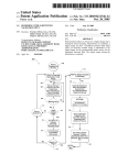
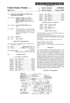
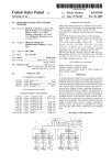
US006024539A
Ulllted States Patent [19]
[11] Patent Number:
Blomquist
[45]
[54]
[75]
Date of Patent:
SYSTEMS AND METHODS FOR
4,656,603
4/1987 Dunn .
COMMUNICATING WITH AMBULATORY
MEDICAL DEVICES SUCH AS DRUG
4,731,051
4,731,058
4,754,401
3/1988 Fischell ~
3/1988 Doan- _
Inventor:
Michael L. Blomquist, Coon Rapids,
[*l
This patent issued on a continued pros-
0 233 115
9/1987
0 319 272
6/1989
1.53(d), and is subject to the tWenty year
patent term provisions of 35 U_S_C_
154(a)(2)_
European Pat. Off. .
France '
OTHER PUBLICATIONS
“A Programmable Infusion Pump Controller,” 30th Annual
Conference on Engineering in Medicine and Biology, Nov.
5—9, 1977 in Los Angeles, California, 11 pages.
[21] Appl- N05 08/868,913
(List continued on neXt page.)
Jun‘ 4’ 1997
Primary Examiner—Charles G. Freay
-
-
Related U'S' Apphcatlon Data
[63]
European Pat 04- -
2 675 288 10/1992
ecution application ?led under 37 CFR
[22] Flled:
6/1988 KaCZYIlSkl et al. .
FOREIGN PATENT DOCUMENTS
Assignee: SIMS Deltec, Inc., 51. Paul, Minn.
NOIiCeI
*Feb. 15, 2000
(Llst Con?rmed on next page)
MiIlIL
[73]
6,024,539
Assistant Examiner—Ehud Gartenberg
Attorney, Agent, or Firm—Merchant & Gould RC.
Continuation of application No. 08/586,952, Jan. 16, 1996,
abandoned, which is a continuation of application No.
[57]
Pat NO_ 5338 157_
n1cat1ng W1th ambulatory
to medical devices, such as drug
7’
7
ABSTRACT
delivery devices, both locally and remotely. In one
[51]
Int. Cl.
.................................................... .. F04B 41/06
embodiment, a Caregiver drug pump Communicates With a
[52]
US. Cl. ........................... .. 417/63; 364/188; 395/340
Of Search .................................. ..
53,
remote patient drug pump for data gathering, trouble
Shooting, and Operational program Changes_ The Caregiver
364/ 188; 702/81, 122; 128/904; 345/340,
348, 349, 350, 351
drug pump is substantially identical in con?guration to the
patient drug pump. The caregiver drug pump transmits
caregiver key input signals to the remote patient drug pump.
The patient drug pump receives the key input signals,
[56]
References Cited
accesses a desired program, and transmits information for
US' PATENT DOCUMENTS
112947733 3/1988 Peterson et a1__
display on the display of the caregiver drug pump. In another
embodiment, a computer is provided for communicating
4,091,550
5/1978 shrenk et a1_ _
locally and/or remotely With a drug pump. The computer
4,098,267
4,396,977
7/1978 Stein et al. .
8/1983 Slater et al. .
may include a display With an image of a pump. The
computer may be operated through the use of a mouse or
4,413,314 11/1983 Slater et a1-475597038 12/1985 Berg et al' 4’565’542 1/1986 Berg '
touch screen With respect to the image of the pump, to
simulate use of the pump While using the personal computer.
The computer may also be used as a training aid for training
4,606,353
476247661
8/1986
TlIIlIIl .
11/1986 Arimond _
4,649,499
3/1987 Sutton et al. .
4,650,469
3/1987 Berg et al. .
.
.
a careglver and/or pat1ent hoW to use the drug pump.
13 Claims, 10 Drawing Sheets
6,024,539
Page 2
“Product Overview, Verifuse Ambulatory Infusion Pump,”
US. PATENT DOCUMENTS
4,756,706
4,778,449
Block Medical Inc., dated Sep. 1990, 4 pages.
Peter Lord et al. “MiniMed Technologies Programmable
7/1988 Kerns et al. .
10/1988 Weber et al. .
4,810,243
3/1989
4,832,033
4,847,764
4,889,132
4,898,578
5/1989
7/1989
12/1989
2/1990
Howson .................................. .. 604/31
Maher et al. .
Halvorsen .
Hutcheson et al. .
Rubalcaba .
Implanatable Infusion System,”pp. 66—71, from Annals of
the New York Academy of Sciences, Neurological Applica
tions of Implanted Drug Pumps, copyright 1988.
DertouZos, M., “Communications, Computers & Net
works,” Scienti?c American Sep. 1991, pp. 62—69.
4,901,221
2/1990 Kodosky et al. .
Dehne, T., “PC—Based Data Acquisition and Instrumenta
4,918,930
4/1990 Gaudet et al. ......................... .. 62/55.5
4,925,444
4,933,873
5/1990 Orkin et al. .
6/1990 Kaufman et al. .
tion,”Analytical Chemistry, vol. 62, No. 9, May 1, 1990, pp.
565A, 566A, 568A, 570A, 571A, 572A.
4,942,514
7/1990 Miyagaki et al. .
4,954,818
4,957,690
4,970,664
5,032,978
5,038,800
5,078,683
5,084,828
5,100,380
5,116,312
9/1990
9/1990
11/1990
7/1991
8/1991
1/1992
“allyTM Ambulatory Drug Infusion System”, Q—Life Sys
tems Inc., 3 pages.
Nakane et al. .
Fennern .
Kaiser .
Watson et al. .
Oba .
Sancoff et al. .
Fundamentals of Interactive Computer Graphics, Foley et
al., Mar., 1993, pp. 10, 11, 29—35.
Imed Status Infusion Management System literature, 6
pages.
Linkens et al., Computer Control Systems and Pharmaco
1/1992 Kaufman et al. .
logical Drug Administration: A Survey, Journal of Medical
Engineering & Technology, vol. 14, No. 2, Mar./Apr. 1990,
3/1992 Epstein et al. .
5/1992 Blankenship et al. .
pp. 41—54.
5,131,816
5,153,827
7/1992 Brown et al. .
10/1992 Coutre et al. .
5,155,693
10/1992 Altmayer et al. .
tems,” Design News, May 21, 1990, pp. 72—73.
5,157,928
10/1992 Gaudet et al. ......................... .. 62/55.5
National Instruments Document entitled “Scienti?c Data
5,168,441
5,172,698
12/1992 Onarheim et al. .
12/1992 Stanko .
Analysis,” 16 pages.
National Instruments’
1990, 20 pages.
National Instruments’
1991, 20 pages.
National Instruments’
1990, 18 pages.
National Instruments’
1990, 16 pages.
5,176,004
5,190,442
1/1993
3/1993
5,207,642
5/1993 Orkin et al..
5,224,051
5,230,623
6/1993
Johnson .
7/1993
Guthrie et al. .
5,241,461
8/1993 Georges .
5,247,434
5,256,157
5,291,190
5,295,062
5,301,301
9/1993
10/1993
3/1994
3/1994
McCarthy, L.H. “Software Simulates Instrumentation Sys
Gaudet .................................. .. 417/901
Jorritsma ................................. .. 417/12
Peterson et al. .
Samiotes et al. .
Scarola et al. .
Fukushima .
Instrumentation Newsletter, Feb.
Instrumentation Newsletter, May
Instrumentation Newsletter, Nov.
National Instruments LabWindows 2.0 materials, 6 pages.
National Instruments LabWindows 1.2 materials dated Oct.,
1989, 5 pages.
4/1994 Kokosky .
5,315,530
5,321,601
5,353,316
5,363,482
5/1994
6/1994
10/1994
11/1994
5,376,070
12/1994 Pun/is et al. ............................ .. 604/31
5,386,360
5,400,246
5,412,400
5,432,709
5,479,643
5,481,250
1/1995
3/1995
5/1995
7/1995
12/1995
1/1996
5,485,408
Instrumentation Newsletter, Aug.
Gerhardt et al. .
Riedel et al. .
Scarola et al. .
Victor et al. .
Bedder, M. et al., “Cost Analysis of Two Implantable
Narcotic Delivery Systems,” Journal of Pain and Symptom
Management, vol. 6, No. 6, Aug., 1991, pp. 368—373.
Wilson et al. .
Wilson et al. .
Takahara et al. .
Vollweiler et al. .
Bhaskar et al. .
Hano .
Sheppard, L.C., Computer—based Clinical Systems: Auto
mation and Integration, 39th Annual Conference on Engi
neering in Medicine and Biology, Baltimore, Maryland, Sep.
13—16, 1986, pp. 73—75.
Principles and Guidelines in Software User Interface
Design, Deborah J. Mayhew, Chapter 9 Dialog Styles:
Direct Manipulation, copyright 1992, 17 pages.
1/1996 Blomquist .
5,718,562
2/1998 Lawless et al.
5,719,761
2/1998 Gatti et al. ............................ .. 364/130
417/1
OTHER PUBLICATIONS
Advertisement from HERCO, “Are Control Rooms Obso
lete?” dated Mar., 1971, 1 page.
Advertisement from HERCO, “Are Control Rooms Obso
lete?”, dated Mar., 1972, 1 page.
“Block Medical: Growing with Home Infusion Therapy,” In
Vivo, The Business and Medicine Report, Apr. 1991, 3
Electronics Feb. 1990 article entitled “Who Will Dominate
pages.
Designing the User Interface, Ben Shneiderman, Chapter 5
Direct Manipulation, Oct., 1993, 56 pages.
The Orange County Register, Nov. 21, 1991 article entitled
Abbott Literature, 37 pages.
Baxter literature for MultiPlexTM Series 100 Fluid Manage
ment System, 2 pages.
Baxter literature for MultiPlexTM Series 100 Fluid Mange
ment System, copyright 1988, 2 pages.
Baxter literature for Flo—Gard® 6201 Volumetric Infusion
Pump, copyright 1992, 2 pages.
San Diego Executive, “A Better Mousetrap,” Sep., 1989, pp.
8—10.
Blade—Citizen, “Entrepreneur takes aim at home health care
market,” Dec. 31, 1989, 2 pages.
the Desktop in the ’90s?”, 3 pages.
“Portable IV frees patients,” 1 page.
Article by McMorris, et al., “Are Process Control Rooms
Obsolete?”, Control Engineering, dated Jul., 1971, pp.
42—47.
LabVIEW®2 User Manual, Jan. 1990 Edition, cover page
and pp. 2—1 through 2—36.
National Instruments’ 1991 catalog entitled “IEEE—488
and VXIbus Control, Data Acquisition, and Analysis,” cover
page and pp. 1—1 through 1—13, 1—38, 4—68, and 4—69.
6,024,539
Page 3
Abbott Laboratories Blue Line System Life Care® Model 4
Series System brochure, copyright 1990, 16 pages.
Video tape—University of Maryland at College Park MD.
Hurnan—Cornputer Interaction Laboratory, Apr, 1991.
Video tape—University of Maryland at College Park MD.
Hurnan—Cornputer Interaction Laboratory, Apr, 1992.
U.S. Patent
Feb. 15,2000
Sheet 1 0f 10
6,024,539
10
FIG. 1
I'l-u
FIG. 2
(so
/
'l C
I
2 100-7 if 54
U.S. Patent
Feb. 15,2000
Sheet 2 0f 10
FIG. 1A
40-\
F 46'
f 42
41--\
420
\ 46G
f ‘5
\_ 450
I
4'90
/— 430
>
/— 4-4-0
6,024,539
U.S. Patent
Feb. 15,2000
Sheet 3 0f 10
6,024,539
FIG. 3
r
0 62
100
U.S. Patent
Feb. 15,2000
Sheet 4 0f 10
6,024,539
PATIENT PUMP INITIAUZATION
IS PATIENT
PUMP IN
SLAVE MODE
PUMP MODE
PUMP OPERATES
NORMALLY
?
PATIENT PUMP
MECHANISM DISABLED
HAS KEY INPUT
SIGNAL BEEN RECEVED
FROM CAREGNER
PUMP‘?
KEY INPUT SIGNAL RUNS
PROGRAM IN PATIENT PUMP
I
PROGRAM UPDATES DISPLAY
ON PATIENT PUMP
I
DISPLAY SIGNAL SENT
TO CAREGNER PUMP
FIG. 4
U.S. Patent
Feb. 15,2000
Sheet 5 0f 10
6,024,539
250
\
CAREGIVER PUMP INITIAUZATION
IS CAREGIVER'
PUMP IN MASTER
MODE
?
“0
PUMP OPERATES
NORMALLY
CAREGIVER PUMP
MECHANISM DISABLED
HAS KEY BEEN
PRESSED 0N CAREGNER
PUMP
?
KEY INPUT SIGNAL SENT
TO PATIENT PUMP
HAS DISPLAY
SIGNN. BEEN RECEIVED
FROM PATIENT PUMP
DISPLAY SIGNAL UPDATES
DISPLAY ON CAREGNER PUMP
FIG. 5
U.S. Patent
Feb. 15,2000
Sheet 6 0f 10
6,024,539
300
( 302
304
I
CAREGNER PUMP
CAREGIVER CONNECTS CAREGIVE? MODEM
CABLE TO CAREGIVER PUMP AND
INSTRUCTS PATIENT TO CONNECT
PATIENT MODEM CABLE TO PATIENT
PUMP.
PUMP TELLS MODEM TO
TURN ON SPEAKER
CAREGIVER ASKS PATIENT TO VERIFY
THAT PATIENT PUMP HAS RESPONDED
WITH "PRESS ENTER TO START SLAVE
COMMUNICATIONS" MESSAGE ON THE
DISPLAY. CAREGNER INSTRUCTS
w
PATIENT PUMP
PATIENT CONNECTS PATIENT MODEM
CABLE TO PATIENT PUMP
PATIENT TO PRESS ENTER KEY. THEN.
WITHOUT HANGING UP THE PHONE. TO
LISTBI FOR FURTHER INSTRUCTIONS.
COMING FROM THE MODEM SPEAKER.
PATIENT PRESSES ENTER KEY
PUMP TELLS MODEM TO START SLAVE
COMMUNICATIONS. PUMP STARTS TWO
MINUTE TIME OUT WHILE WAITING FOR
CARRIE? DETECT FROM MODEM.
MODEM GOES OFF-HOOK
MODEM DISCONNECTS PHONE
MODEM TURNS ON SPEAKER
MODEM SENDS SHORT BEEP TO CAREGNER
PUMP THEN USTBIS FOR CARRIER
FIG. 6A
U.S. Patent
Feb. 15,2000
Sheet 7 0f 10
6,024,539
300
T
302
I
304
T
CAREGIVH? HEARS SHORT MODEM BEEP PATIENT SETS PHONE DOWN
EITHER FROM PHONE HANDPIECE OR
WITHOUT HANGING UP
MODEM SPEAKER AND KNOWS THAT
THE PATIENT PUMP IS READY
CAREGNER PRESSES ENTER KEY
PUMP TELLS MODEM TO START MASTER
COMMUNICATIONS, THEN PUMP WAITS
FOR INCOMING DATA. PUMP STARTS TWO
MINUTE TIME OUT WHILE WAITING FOR
RESPONSE FROM PATIENT PUMP
MODEM GOES OFF-HOOK
MODEM DISCONNECTS PHONE
MODBA SDIDS CARRIER
cAREGIvER SETS PHONE DOWN
MODEM RECEIVES CARRIER, THEN
wrrHour HANGING UP
SENDS "CARRIER RECEIVE)" sIGNAL
T0 PATIENT PUMP
PUMP TELLS MODEM T0
SHUT OFF SPEAKER
MODBII SHUTS OFF SPEAKER
PUMP SENDS "I'M HERE" SIGNAL TO
CAREGNER PUMP
PUMP ACKNOWLEDGES "I'M HERE"
SIGNAL AND SENDS "OK TO BEGIN"
SIGNAL TO PATIENT PUMP
PUMP TELLS MODEM To SHUT OFF SPEAKER
MODEM SHUTS OFF SPEAKER
PUMP SENDS KEY INPUT SIGNALS
T0 PATIBIT PUMP
PATIBIT PUMP RECEVES "OKAY TO
BEGIN" SIGNAL AND SENDS CURRENT
DISPLAY SIGNAL TO CAREGNER PUMP
PUMP SENDS DISPLAY SIGNALS T0
CAREGNER PUMP IN RESPONSE TO
KI-Y INPUT SIGNALS
FIG. 6B
U.S. Patent
Feb. 15,2000
(
4-02
.
Sheet 8 0f 10
I
CAREGNER PUMP
CAREGNER PRESSES STOP/START KEY
PUMP SENDS- "DISCONNECT" SIGNAL
TO PATIENT PUMP
PUMP SBIDS "DISCONNECT" SIGNAL
TO MODEM
MODEM CUTS CARRIER
MODEM CONNECTS PHONE
MODEM TURNS ON SPEAKER
4-04
6,024,539
w
PATIENT PUMP
PUMP ACKNOWLEDGES "DISCONNECT‘
SIGNAL
PUMP BEGINS TO BEEP
PUMP SBIDS "DISCONNECT" SIGNAL
TO MODEM
MODEM CUTS CARRIER
MODEM CONNECTS PHONE
MODEM TURNS ON SPEAKER
CAREGNER UNPLUGS CAREGNER
MODEM CABLE
MODEM DISCONNECTS SPEAKER
MODEM GOES ON HOOK
CAREGNER PICKS UP PHONE THEN
CALLS FOR PATIENT TO PICK UP PHONE.
PATTENT HEARS CAREGNER IN MODEM
SPEAKER AND PICKS UP PHONE
CAREGNER TELLS PATTENT TO
DISCONNECT PATIENT MODEM CABLE
PATTENT DISCONNECTS PATIENT
MODEM CABLE
PUMP STOPS BEEPING
MODEM DISCONNECTS SPEAKER
MODEM GOES ON HOOK
CAREGNER RESUMES NORMAL VOICE
COMMUNICATIONS
PATTENT RESUMES NORMAL VOICE
COMMUNICATIONS
FIG. 7
U.S. Patent
Feb. 15,2000
(502
Sheet 9 0f 10
I
CAREGNER PUMP
PUMP RECEIVES PAGE AND DISPLAYS
PATIENT PAGING MESSAGE
CAREGNER PRESSES STOP/START KEY
PUMP SENDS "DISCONNECT" SIGNAL TO
PATIENT PUMP
PUMP SENDS "DISCONNECT" SIGNAL
TO MODEM
MODEM CUTS CARRIER
MODEM CONNECTS PHONE
MODEM TURNS ON SPEAKS!
6,024,539
504w
PATIENT PUMP
PATIENT PRESSES STOP/START KEY
PUMP SENDS PAGE TO
CAREGNER PUMP
PUMP ACKNOWLHDGES "DISCONNECT"
SIGNAL
PUMP BEGINS TO BEEP
PUMP SENDS "DISCONNECT" SIGNAL
TO MODEM
MODEM CUTS CARRIER
MODEM CONNECTS PHONE
MODEM TURNS ON SPEAKER
CAREGNER UNPLUGS CAREGNER
MODEM CABLE
MODEM DISCONNECTS SPEAKER
MODEM GOES ON HOOK
CAREGNER PICKS UP PHONE THEN
CALLS FOR PATIENT TO PICK UP PHONE.
PATIENT HEARS CAREGNER IN MODEM
SPEAKER AND PICKS UP PHONE
CAREGNER TELLS PATIENT TO
DISCONNECT PATIENT MODEM CABLE
PATIENT DISCONNECTS PATIENT
MODEM CABLE
PUMP STOPS BEEPING
MODEM DISCONNECTS SPEAKER
MODEM GOES ON HOOK
CAREGNER RESUMES NORMAL VOICE
PATIENT RESUMES NORMAL VOICE
COMMUNICAIIONS
COMMUNICATIONS
FIG. 8
U.S. Patent
Feb. 15,2000
Sheet 10 0f 10
6,024,539
FIG. 9
FIG. 10
98
U
>
92
OOO
OOO
6,024,539
1
2
SYSTEMS AND METHODS FOR
COMMUNICATING WITH AMBULATORY
MEDICAL DEVICES SUCH AS DRUG
DELIVERY DEVICES
There may further arise a need for the caregiver to access
the controller, such as the processor and the programs, Which
controls operation of the ambulatory medical devices. For
example, in the case of drug delivery devices, some thera
pies change over time. The caregiver may need to access the
operating program in order to change the operation of the
This is a Continuation of application Ser. No. 08/586,
952, ?led Jan. 16, 1996 noW abandoned, Which is a Con
drug delivery device. Further, some drug delivery devices,
for example, may be used for very different applications,
tinuation of patent application Ser. No. 08/276,025, ?led Jul.
15, 1994, noW issued as US. Pat. No. 5,485,408, Which is
a Continuation of patent application Ser. No. 07/942,288,
?led Sep. 9, 1992, noW issued as US. Pat. No. 5,338,157.
requiring different operating programs. These operating pro
10
FIELD OF THE INVENTION
The present invention relates generally to ambulatory
medical devices and methods for communicating With such
15
devices. In particular, the present invention relates to sys
tems and methods for locally and remotely communicating
With drug delivery devices.
BACKGROUND OF THE INVENTION
Various ambulatory medical devices are knoWn for treat
the drug pump. The caregiver may visit the patient at the
patient’s home at some point after the drug therapy has
begun using the drug pump. The caregiver may sample the
20
patient’s blood. The caregiver returns to the of?ce and the
25
blood sample is analyZed. The results of the blood analysis
may indicate the patient is not receiving the proper drug
therapy. This usually means the controller of the drug pump
must be adjusted to give the proper therapy to the speci?c
patient. To adjust the controller, the caregiver needs to be
ing and/or monitoring patients at a remote site aWay from the
caregiver’s or clinician’s office. One eXample of an ambu
latory medical device is a drug delivery device, such as a
drug pump, for providing periodic or continuous drug deliv
ery to the patient When the patient is aWay from the
caregiver’s office.
Certain drugs rarely achieve their maXimum therapeutic
action through conventional injection techniques. Many
drugs reach their full potential only through precise delivery
able access the controller.
Another problem facing caregivers in the area of ambu
latory medical devices relates to the ease of remote com
30
over an eXtended period of time. With controlled drug
infusion through a drug pump, the drug can be given at a
precise rate that Will keep the drug concentration Within the
therapeutic margin and out of the toXic range. Ambulatory
drug pumps can provide appropriate drug delivery to the
35
hospital or caregiver’s of?ce.
A failure to adequately monitor the drug pump and the
delivery therapy. In some cases, the drug therapies can have
serious health consequences to the patient if the drugs are
not administered properly.
Several concerns arise When the patient utiliZes the vari
45
In the case of remote communication With a patient’s
medical device using a personal computer/base station, the
caregiver also needs to remain near the personal computer/
base station, or else transport the personal computer/base
station With the caregiver, if the caregiver Wishes to remain
in communication With the patient’s medical device.
It sometimes may become necessary to communicate With
a personal computer or base station either locally or
ambulatory medical device gathers data With respect to the
device and/or the patient, the data needs to be easily acces
sible by the caregiver to permit the caregiver to monitor the
device and the patient. Often, the patient may be of little or
no assistance in accessing the data and communicating With
the caregiver from the remote site. If the caregiver needs to
remotely in order to take advantage of the greater data
handling or processing capability of the personal computer
55
or base station, for eXample. The ability of the caregiver to
communicate easily With the pump using a personal com
puter or base station may be important in those circum
stances. In addition, the patient may be able to do very little
to assist the caregiver in linking the remote medical device
to the local personal computer/base station.
There is a need for systems and methods for communi
cating With ambulatory medical devices such as drug deliv
ery devices, both locally and remotely, Which addresses the
visit the patient. If the caregiver attempts to trouble shoot
from a remote site, the patient may be unable physically or
medical device. The caregiver must then be knowledgeable
both in operation of the medical device and in operation of
the personal computer/base station. This concern also
applies to local communication With the ambulatory medical
device.
40
ous ambulatory medical devices at remote sites. If the
physically handle the device to access the data, the device
and caregiver must be brought to the same location.
Similar problems can also arise in that the medical
devices may fail or be used improperly at the remote sites.
If the device is not operating properly, the device may have
to be brought to the caregiver, or the caregiver may have to
munication With the devices, if such remote communication
capability is provided. Remote communication With an
ambulatory medical device using a personal computer or
base station may be dif?cult for some caregivers, if the
personal computer/base station operates differently than the
patient at a controllable rate Which does not require frequent
medical attention and Which alloWs the patient to leave the
patient’s usage of the drug pump can reduce or eliminate any
bene?ts the patient may have received from a proper drug
grams can be changed as the use of the drug delivery device
changes. Resources may not be used ef?ciently if the car
egiver and the device must be brought to the same location
for the caregiver to access the processor and operating
programs.
One speci?c situation often arises in the case of a drug
pump Where the caregiver needs to access the controller of
above concerns and other concerns.
60
mentally to suf?ciently cooperate With the caregiver for the
SUMMARY OF THE INVENTION
caregiver to trouble shoot from the remote site. Operating
The present invention relates to systems and methods for
communicating With an ambulatory medical device, such as
a drug delivery device, and in particular, a drug pump. In one
embodiment, a communication system is provided Where a
remote drug pump communicates With a similar local drug
pump. Each of the drug pumps are provided With a pump
problems can arise at inconvenient times, such as at night or
on Weekends and holidays. The caregiver may also need to
be able to easily periodically monitor the patient’s usage of
the medical device to observe patient compliance With
prescribed treatments While the patient is at the remote site.
65
6,024,539
4
3
controller for controlling operation of the pump. The con
In one embodiment, the caregiver pump and the patient
pump both include program means for operating in both the
master and slave modes. Automatic selection of the master
or slave mode from the normal pumping mode is provided
When a communications cable is connected to the respective
pump.
troller may include a processor and associated memory for
storing operating programs and other information. The
pumps each include a pumping mechanism controlled by the
controller for pumping ?uid to a patient in the normal
pumping mode of operation.
Interconnect structure, such as modems, is provided to
permit interconnection of the controllers of the pumps in the
pump to pump communications mode of operation. The
interconnect structure permits communication betWeen the
Various program means and sequences are disclosed for
communication betWeen the local caregiver pump and the
remote caregiver pump to facilitate e?icient communication
10
While emphasiZing easy usage by the caregiver and by the
patient, some of Whom may have di?iculty carrying out
instructions from the caregiver over the telephone.
In another embodiment, systems and methods are pro
respective processors over a communications medium, such
as conventional telephone communication lines. The tele
phone lines also permit initial voice communication betWeen
the patient and the caregiver using conventional telephones
vided for communicating betWeen a remote pump and a
or other devices before the pumps are linked together for the 15 local caregiver computer, such as a personal computer. Such
pump to pump communications mode of operation. The
communication may permit greater data processing utiliZing
modems may include speakers to facilitate ease of operation
the computer’s data handling capability. Also, communica
during pump to pump communication With patients Who
have di?iculty in cooperating With the caregiver due to
mental and/or physical limitations.
Each drug pump includes operator input structure for
making operator inputs to the controller of the respective
pump. The operator input structure is useful for selecting
tion With the remote pump using the local computer may be
useful for recertifying the remote pump periodically as is
sometimes required With respect to medical devices. The
local computer may also be useful in changing or adjusting
the pump operations program of the remote pump. Modem
desired pump control programs or desired pump data or both
communications medium, such as conventional telephone
lines, betWeen the remote pump and the local computer.
from the memory of the processor of the pump. The infor
mation selection structure may include a keypad comprising
communication structure permits communication over a
25
In a further embodiment, modem communication struc
a plurality of keys.
ture is provided Which links a local pump to a local com
puter. Preferably, the modem communication structure also
includes structure for further permitting communication
Display structure on each pump is interconnected to the
controller of the respective pump. The display structure
displays information about operations of the pump sent to
the display structure by the controller. The display structure
may display desired information from the memory of the
betWeen the local computer or the local pump and a remote
processor, such as information relating to the normal pump
ing operations mode of the pumping mechanism. Other
information that may be displayed may relate to various
sensor outputs to the controller. Other information displayed
35
may relate to the pump to pump communications mode. The
display structure may include an LCD dot matrix display.
tWo pumps to communicate in such a Way during pump to
pump communications that one pump controls the functions
likely already familiar With operation of the patient pump,
thereby saving training time because the caregiver pump
operates similarly to the patient pump. Further, the caregiver
In another embodiment of the invention, a computer
system is provided, With a processor and memory, Which is
programmed to display an image of a pump on a display that
resembles the pump utiliZed by the patient. The image
includes representations of the keys and the display of an
actual pump. The computer is further programmed such that
Information programmed into the controllers alloWs the
of the other. Information programmed into the local drug
pump, or caregiver pump, instructs that the caregiver pump
be put into the master mode at some point during operation.
In the master mode, the local caregiver pump sends its
keyboard inputs to a remote patient pump. The caregiver
pump also receives its display inputs from the remote patient
pump. The caregiver pump is used by the caregiver for such
purposes as data gathering, trouble shooting, and operational
program changes With respect to the remote patient pump.
Ease of communication is provided since the caregiver is
pump. This modem communication structure permits: (1)
local pump and local computer communication; (2) local
pump and remote pump communication; and (3) remote
pump and local computer communication.
the image of the pump is utiliZed to communicate With an
actual remote pump or an actual local pump by manipulating
45
or activating the keys on the image of the pump. The keys
of the image can be activated by such techniques as through
the use of a mouse or a touch screen. Activating the keys of
the image of the pump simulates for the caregiver the
presence of an actual pump. This facilitates reductions in
training time for training the caregiver to communicate With
the patient’s pump, since the caregiver is most likely already
familiar With operation of the patient’s pump.
The computer system With the pump image program may
also be used as a simulator for training the caregiver or the
patient hoW to use the pump. The simulator includes various
55
can remain in constant communication With the patient
pump by merely transporting the caregiver pump and a
modem With the caregiver at all times.
The remote patient pump has information programmed
into the controller that instructs the patient pump to be put
into the slave mode at the appropriate time. In the slave
programs for simulating for the patient trainee and/or the
caregiver trainee various pump operations situations With a
patient’s pump for pumping ?uid. The simulator also
includes various programs for simulating for the patient
trainee and/or the caregiver trainee various communication
situations With a patient’s pump.
These and other features of the present invention are
mode, the patient pump receives its keyboard input signals
described in greater detail in the detailed description of the
primarily from the caregiver pump. The patient pump sends
preferred embodiments.
its display signals to the caregiver pump. In one
embodiment, the slave mode of the patient pump disables
the patient pump from actually pumping the ?uid during
communication With the caregiver pump.
65
BRIEF DESCRIPTION OF THE DRAWINGS
In the draWings, Where like numerals refer to like features
throughout the several vieWs:
6,024,539
5
6
FIG. 1 is a schematic diagram illustrating a ?rst system of
local pump and remote pump communications.
FIG. 1A is a schematic diagram illustrating components
of the remote pump shoWn in FIG. 1.
FIG. 2 is a schematic diagram illustrating a second system
using a personal computer to communicate With a local
patient. Speci?c components of patient pump 40 are shoWn
in greater detail in FIG. 1A. Caregiver pump 20 is preferably
pump and/or a remote pump. Local pump and remote pump
?uid communication structure 47a, such as a tube. The ?uid
reservoir 47 may be a cassette mounted to pump 40, or the
?uid reservoir may be a container located at a remote site
from pump 40, both interconnected to pump 40 With a ?uid
communication tube 47a. To pump ?uid to a patient, the
identical to patient pump 40 With respect to the features
shoWn in FIG. 1A.
Pump 40 as shoWn in FIG. 1A includes a pumping
mechanism 43 and a ?uid reservoir 47 interconnected by a
communications capability is also shoWn.
FIG. 3 is a schematic diagram of a modem useful in the
communication system shoWn in FIG. 2 to interconnect a
personal computer, a local pump, and a remote pump.
FIG. 4 is a ?oW chart of an operational sequence of the
patient pump With respect to the normal pumping mode for
pumping ?uid and the slave mode for pump to pump
communication.
FIG. 5 is a ?oW chart of an operational sequence of the
10
15
pump is also interconnected to the patient, such as through
a tube 40a. The pumping mechanism 43 pumps ?uid from
the reservoir 47 to the patient through the tube 40a inter
connected to the patient.
Pumps 20,40 may be any of a variety of drug delivery
pumps. An eXample of one drug delivery pump is described
in US. Pat. No. 4,559,038, incorporated herein by reference.
In US. Pat. No. 4,559,038, a rotating camshaft is provided
Which engages tWo reciprocating valves and a reciprocating
eXpulser. The valves and eXpulser engage a tube intercon
caregiver pump With respect to the normal pumping mode
for pumping ?uid and the master mode for pump to pump
communication.
FIGS. 6A and B comprise a single ?oW chart of opera
tional sequences involving the caregiver pump and the
patient pump during connection and communication
betWeen the caregiver pump and the patient pump When the
nected in ?uid communication betWeen a ?uid reservoir and
patient pump is located at a remote site. FIG. 6B folloWs 25
after FIG. 6A during operations.
the patient. The rotating camshaft moves the valves and
eXpulser to pump ?uid through the tube.
In the communication system 10 of FIG. 1, only patient
Wants to discontinue communication betWeen the caregiver
pump and the patient pump at some time during remote
pump 40 is utiliZed to pump ?uid to the patient. Caregiver
pump 20 is used by the caregiver to communicate With
patient pump 40. Caregiver pump 20 is preferably not used
to pump ?uid during pump to pump communication With
communication betWeen the caregiver pump and the patient
patient pump 40. HoWever, caregiver pump 20 could be used
FIG. 7 is a ?oW chart of operational sequences involving
the caregiver pump and the patient pump When the caregiver
to pump ?uid to a patient before or after communication
pump.
FIG. 8 is a ?oW chart of operational sequences involving
the caregiver pump and the patient pump When the patient
Wishes to speak to the caregiver at some time during remote
35
Pumps 20,40 each include a controller for controlling
operation of the pumping mechanism utiliZed to pump ?uid.
Pump 40 shoWn in greater detail in FIG. 1A includes a
controller 41 interconnected to pumping mechanism 43
through connection structure 43a. The controller 41 prefer
ably includes a processor and memory programmable With
communication betWeen the caregiver pump and the patient
pump.
FIG. 9 is a schematic diagram shoWing a computer screen
displaying an image of a pump, as part of a computer system
used for communicating With a pump.
FIG. 10 is a schematic diagram shoWing a second com
puter screen displaying an image of a pump, as part of a
selected functions for controlling operation of the pumping
mechanism 43. As shoWn in FIG. 1A, the controller 41 is
computer system, and including information displayed on
the screen relating to simulation sequences for use in train
mg.
With patient pump 40, should the need arise. In some cases,
caregiver pump 20 could be used to pump ?uid during pump
to pump communications With patient pump 40.
also connectable to one or more electrical sensor elements in
45 the pump, such as sensors 45,49.
A variety of sensors like sensor 45 may be provided
depending on the type of pump and the intended usage of the
pump. For example, since the ?uid is pumped through a tube
40a to the patient by the pump, the pump may include a
DESCRIPTION OF THE PREFERRED
EMBODIMENTS
Referring noW to FIG. 1, a system 10 of communication
betWeen a local drug pump 20 (or caregiver pump) and a
doWnstream high pressure sensor to detect When an occlu
remote drug pump 40 (or patient pump) is shoWn. In system
sion of the tube has occurred. A sensor may also be provided
10, local pump 20 is functioning as a caregiver pump for use
to sense When a vacuum develops in tube 47a upstream from
by the caregiver at the site 32 Where the caregiver is located,
the pump betWeen the pump mechanism 43 and the ?uid
reservoir 47, indicating a lack of ?uid to be pumped. Other
such as the caregiver’s office. Site 32 may be the caregiver’s
home, during on call periods, or even the caregiver’s
automobile, if the automobile is provided With some com
55
sensors may be provided to sense pump electrical poWer
supply status. Still other sensors may be provided to monitor
munications capability for sending and receiving signals
the operation of the mechanical components comprising the
With respect to another site. In system 10, the caregiver
operating pump 20 is typically a nurse, physician, therapist,
ambulatory patient pump for pumping drugs to the patient
pumping mechanism. The sensors, like sensor 45, all typi
cally send a suitable electrical signal to the processor of
controller 41 through connection structure, like structure
45a, indicative of the conditions sensed. The controller is
appropriately programmed to receive and process the sensor
and is located With the patient at a site remote from caregiver
pump 20, such as at the patient’s home 52. Also, site 52 may
signals it receives. Sensor 49 relates a particular sensor
useful during pump to pump communications to assist the
or other medical personnel.
In system 10, remote pump 40 is functioning as an
be the patient’s Workplace.
Pumps 20,40 each include a pumping mechanism Which
is capable of pumping ?uid from a ?uid reservoir to a
65
operators (both patient and caregiver) in communication
betWeen the pumps, Which Will be discussed in greater detail
beloW.
6,024,539
7
8
The controller 41 includes memory for storing various
programs and data related to operation of the pump. The
modem 28 located locally With respect to caregiver pump
20. Caregiver pump 20 is interconnected to modem 28
processor runs the desired operating programs to control
through connection structure 30, such as an RS232 serial
cable. Caregiver pump 20 and modem 28 may be located at
operation of the pumping mechanism 43. The processor
further responds to the sensor input signals by generating
appropriate control output signals in accordance With its
programmed control logic. Access to the processor is pro
the caregiver’s office 32, at the caregiver’s home during
on-call periods, or even at a mobile site, such as the
caregiver’s automobile.
vided through an external communication port 42. For
caregiver pump 20, access to the processor is provided
through an external communication port 22 (see FIG. 1).
Both caregiver pump 20 and patient pump 40 can be
utiliZed for pumping or delivering a drug to a patient When
Communication port 42 permits interconnection of the
controller of patient pump 40 to modem 48 With connection
10
structure 50, such as an RS232 serial cable. Patient pump 40
and modem 48 are both located remotely to caregiver pump
20 and modem 28, such as at the patient’s home or Work
the respective pump is interconnected to the patient. Pumps
place 52, or other location remote from caregiver pump 20.
Communication betWeen pump 20 and pump 40 through
20,40 are preferably identical With respect to the electrical
and the mechanical ?uid pumping functions. One advantage
of this is that caregiver pump 20 can be an unused spare 15 modems 28,48 is over communications medium 54 such as
conventional telephone lines, cellular phones, ?ber optics
patient pump 40. As Will be discussed beloW, the respective
controllers of pumps 20,40 may be programmed differently
links, satellite links, microWave links, or other. Modems
28,48 preferably communicate at 9600 bps and include error
correction and data compression features over conventional
to operate in the appropriate desired manner during pump to
pump communications. As Will also be discussed, this
telephone lines.
programming can be done locally or remotely. Preferably,
pumps 20,40 include appropriate programs to operate either
One advantage of the present invention is that the car
egiver can communicate With the patient pump 40 using a
similar pump, the caregiver’s pump 20. The caregiver pre
as a master pump or as a slave pump during pump to pump
communications. In some cases, the programs in each pump
that control operation of the pumping mechanism Will be
different. This Will also be discussed in more detail beloW.
25
communicate With patient pump 40 to access the processor
of patient pump 40 from a remote location.
Communication betWeen the controller of the remote
One preferred processor that may be used in connection
With pumps 20,40 is a MC68HCllE9 high-density compli
mentary metal-oxides semiconductor (HCMOS) high
performance microcontroller unit (MCU) by Motorola. Such
patient pump 40 and the controller of the local caregiver
pump 20 permits remote data gathering from the remote
processor includes 512 bytes of electrically erasable pro
grammable ROM (EEPROM), and 512 bytes of RAM.
Pumps 20,40 each include operator input structure for
permitting an operator of the respective pump to communi
cate With the controller of the pump, speci?cally the internal
processor of the pump and the information in the internal
memory. In one preferred embodiment, a plurality of opera
tor keys 24 on caregiver pump 20 are provided for pressing
sumably has knoWledge of operation of patient pump 40.
This knoWledge is useful in utiliZing caregiver pump 20 to
patient pump by the local caregiver pump. Such data gath
ering may be useful for periodic monitoring of the patient
35
pump 40 during use of the patient pump at the remote site.
Data gathering may also be useful at the end of the patient
use.
Communication betWeen the remote patient pump 40 and
the local caregiver pump 20 permits troubleshooting With
by the caregiver. Preferably, each key has at least one
function. Keys 24 send a signal to the controller of caregiver
pump 20 indicative of the key pressed by the caregiver. The
respect to the remote patient pump, Without the caregiver
being located at the same location as the patient’s pump.
Remote troubleshooting is useful in the case Where patients
controller of pump 20 responds in the desired manner if an
are unfamiliar With the some of the more sophisticated
acceptable key press is made by the caregiver.
operations of their pump. Also, remote troubleshooting
Patient pump 40 has keys 44 preferably identical to keys
24. Keys 44 send a signal to the controller of patient pump
40 indicative of the key pressed. The controller of patient
using the pump to pump communication system is useful for
45
patients Who have difficulty orally communicating With the
caregiver over the telephone.
pump 40 responds in the desired manner if an acceptable key
Communication With the remote patient pump 40 is also
press is made by the patient. As shoWn in FIG. 1A, keyboard
Caregiver pump 20 includes a display 26 for displaying
useful for accessing the pump operations programs for
changing or adjusting the operation of the remote patient
pump from the local site, thereby saving the caregiver and
the patient time from not having to make an in-person visit.
selected information stored in the controller. In one preferred
embodiment, the display 26 includes an LCD dot matrix
egiver pump 20 permits the caregiver pump 20 to be put into
44 is interconnected to controller 41 through connection
structure 44a.
display. LCD dot matrix display 26 is interconnected to the
controller of caregiver pump 20. Display signals sent from
the controller of caregiver pump 20 permit display of
Information programmed into the controller of the car
a master mode from the normal pumping mode at the
55
information related to operation of pump 20 on display 26.
One preferred LCD dot matrix display is a display With four
lines and tWenty-one characters per line.
Patient pump 40 has a display 46 preferably identical to
display 26 of caregiver pump 20. Display signals sent from
the controller of patient pump 40 display information related
to operation of pump 40 on display 46. As shoWn in FIG. 1A,
display 46 is interconnected to controller 41 through con
nection structure 46a.
Communication port 22 of caregiver pump 20 permits
interconnection of the controller of caregiver pump 20 to a
appropriate time. In the master mode, caregiver pump 20
sends a keyboard input signal indicative of a key 24 pressed
by the caregiver over port 22 to patient pump 40. In the
master mode, caregiver pump 20 receives its display signals
primarily from patient pump 40 via communication port 22.
In the master mode, the key presses on keys 24 of caregiver
pump 20 do not access the memory of caregiver pump 20 for
65
the purposes of programming the memory of caregiver
pump 20 or selecting information for display relating to
caregiver pump 20. The master mode is primarily for
permitting caregiver pump 20 to communicate With the
controller of patient pump 40 for the purposes of program
ming the memory of patient pump 40 or selecting informa
6,024,539
9
10
tion for display relating to patient pump 40 from the memory
of patient pump 40.
With respect to patient pump 40, information pro
grammed into its controller permits patient pump 40 be put
operation of the patient’s pump from the remote site.
HoWever, in some situations it may be desirable for car
egiver pump 20 to begin operation of the pumping mecha
nism of patient pump 40 at a site remote from the location
of the caregiver during pump to pump communications. If a
into a slave mode from the normal pumping mode at the
suitable controller is provided, it may be possible to operate
the pumping mechanism of patient pump 40 While patient
pump 40 is communicating With caregiver pump 20.
appropriate time. In the slave mode, patient pump 40
receives keyboard input signals primarily from caregiver
pump 20 via communication port 42. Patient pump 40 sends
its display signals from communication port 42 to caregiver
pump 20.
Referring noW to FIG. 4, a How chart 200 is shoWn
10
illustrating one preferred operational sequence of patient
To communicate betWeen caregiver pump 20 and patient
pump 40 With respect to the normal pumping mode and the
pump 40 over modems 28,48, caregiver pump 20 is out of
the normal pumping mode and in the master mode.
preferred operational sequence of caregiver pump 20 With
Similarly, patient pump 40 is out of the normal pumping
respect to the normal pumping mode and the master mode.
sufficient capacity may be provided Where the pumps 20,40
operate simultaneously in the normal pumping mode and in
pump With respect to normal pumping operations mode, or
pump to pump communications operations mode (slave and
master modes). FIGS. 4 and 5 speci?cally shoW the
slave mode. FIG. 5 is a How chart 250 illustrating one
mode and in the slave mode. In some cases, controllers With 15 FIGS. 4 and 5 illustrate the operational sequences for each
the master or slave modes.
In system 10, patient pump 40 is at least programmed to
be operable in tWo modes, the normal pumping mode and
sequences With respect to communicating the key input
signals and the display signals betWeen the pumps.
the slave mode. There typically is not a need for patient
pump 40 to operate in the master mode When the patient
shoWn for more speci?c operational sequences folloWed
possesses the patient pump. Further, in system 10, caregiver
during connection and communication betWeen caregiver
pump 20 and patient pump 40, respectively. FloW chart 300
pump 20 is at least operable in the master mode. HoWever,
situations are anticipated Where it is desireable to have one
Referring noW to FIGS. 6A and 6B, a How chart 300 is
25
or both pumps 20,40 include programs for operation in the
normal pumping mode, the slave mode, and the master
of FIGS. 6A and 6B includes a caregiver sequence 302 in the
left hand column and a patient sequence 304 in the right
hand column. FloW chart 300 also includes actions to be
mode. In some cases, caregiver pump 20 may be an unused
taken by the patient and the caregiver during connection and
patient spare. At a later date, the unused patient spare may
be needed as a patient pump. This Would require the slave
mode operating program, and a particular normal operation
mode program suitable for the patient. It may be more
ef?cient for the caregiver if the controller of each pump
20,40 is preprogrammed to include both the master mode
program and the slave mode program. The selection of
master or slave mode may be made by the caregiver by
precon?guring the patient’s pump 40 to enter the slave mode
during pump to pump communication, and not enter the
master mode. The caregiver Would have the capability to
precon?gure the caregiver pump 20 to only enter the master
mode during pump to pump communication, and not the
communication betWeen the tWo pumps.
The How chart 300 of FIGS. 6A and 6B shoWs various
steps including the step of hitting the ENTER key. The
ENTER key is one key of keys 24 on caregiver pump 20 and
keys 44 on patient pump 40.
35
Would ?rst contact each other, such as by voice communi
cation over the telephone 29,49, as shoWn in FIG. 1, to begin
initiation of pump to pump communication. Telephones
29,49 may be conventional telephones including means for
dialing another phone, and a handpiece or other device for
permitting voice communication With the party on the other
slave mode if the caregiver desired . At some point later in
time, the caregiver could recon?gure the caregiver pump 20
to only enter the slave mode during pump to pump com
munications if the caregiver pump 20 Was needed as a
If a caregiver Wanted to monitor or program a patient’s
pump 40 over the phone line 54, the caregiver and the patient
45
patient pump.
end. Prior to initiation of pump to pump communication,
both pumps 20,40 are in the normal pumping mode. At the
top of each column 302,304 of FIG. 6A, pumps 20,40 are in
the normal pumping mode. As shoWn in FIG. 6A, the
caregiver Would ?rst instruct the patient to connect pump 40
pump 20 to patient pump 40, the caregiver is able to access
to modem 48, thereby automatically stopping the pump and
selecting the appropriate processor program for the slave
the controller of patient pump 40, make various inputs using
the caregiver’s pump 20, and receive back display inputs
mode.
Automatic selection of the slave mode and stoppage of the
In system 10 of FIG. 1 Which shoWs linking caregiver
from patient pump 40 such that the caregiver can see the
normal pumping mode in patient pump 40 is provided using
display inputs on the display 26 of caregiver pump 20. Such
suitable logic circuitry and sensor structure, such as sensor
49 in FIG. 1A, to sense the presence of cable 50. Automatic
communication can occur When the patient pump 40 is
located at a remote site from caregiver pump 20. This is 55 selection of the slave mode and stoppage of normal pumping
particularly advantageous in saving resources by reducing
mode by inserting cable 50 into patient pump 40 is useful
the number of in-person visits betWeen the caregiver and the
since it eliminates one or more keyboard entries that might
patient.
otherWise be necessary by the patient or caregiver to place
patient pump 40 in the slave mode from the normal pumping
mode. Alternatively, the patient may have to hit a predeter
In one embodiment, disabling structure is provided With
respect to caregiver pump 20 for disabling the pumping
mined key 44 or ?ip a suitable sWitch to eXit the normal
pumping mode and enter the slave mode if no automatic
selection of the slave mode and automatic stoppage of the
mechanism of caregiver pump 20 such that during pump to
pump communications, the pumping mechanism is disabled.
similarly, for patient pump 40, disabling structure is pro
vided to disable the pumping mechanism of patient pump 40
during pump to pump communications. This may be nec
essary due to processor capability limitations. This may also
be a safety feature to prevent a caregiver from starting
normal pumping mode is provided.
65
In FIG. 1A, sensor 49 is interconnected to communica
tions port 42 through connection structure 49b, and to
controller 41 through connection structure 49a. Sensor 49
6,024,539
11
12
If the communication session Were interrupted by a bad
may include tWo spaced apart pins Which engage the com
munication cable 50 to close an electrical loop When the
phone line, patient pump 40 might remain unchanged or
cable 50 is operatively positioned in communications port
partially programmed. During programming of patient pump
42. Closure of the loop sends a suitable signal to controller
41 that the cable 50 is present and pump to pump commu
nications is desired, ie the slave mode operations program.
40, caregiver pump 20 could get a continuously updated
status report from patient pump 40 through appropriate
programming in caregiver pump 20 and patient pump 40.
The operating system of caregiver pump 20 shall alloW
The caregiver could revieW the status report after discon
necting the pump from the modem to verify that patient
pump 40 had been programmed as desired by the caregiver.
The controller of each pump 20,40 controls operation of
the pump to be placed in the caregiver mode of remote
programming from the normal pumping mode of operation.
Automatic selection of the master mode and automatic
stoppage of the normal pumping mode in caregiver pump 20
is provided using suitable logic circuitry and sensor structure
10
the respective modem 28,48 attached as a peripheral device.
The controller of each pump 20,40 instructs its respective
to sense the presence of cable 30, such as With a similar
sensor to sensor 49 of patient pump 40. Alternatively, the
caregiver may have to hit a predetermined key 24 or ?ip a
suitable sWitch to eXit the normal pumping mode and enter
15
the master mode if no automatic selection linked to insertion
of cable 30 is provided.
Caregiver pump 20 operating in the master mode includes
program means for initiating a modem link to the patient
pump 40 operating in the slave mode, as shoWn in How chart
300 of FIGS. 6A and 6B. The phone connection to the
patient pump 40 shall be assumed to be open. When the
modem link betWeen the pumps is established, each time the
caregiver presses a key 26 on caregiver pump 20, a key input
signal is sent by program means in the controller of car
egiver pump 20 to patient pump 40. Program means in
patient pump 40 responds to the signal as if it Were a key
pressed on its oWn keyboard. Once the processor of patient
pump 40 responds to the key input signal, program means in
and after the voice transmitting and receiving characteristics
of one or both of the telephone hand piece have been
terminated. The modem speakers are useful if the patient or
caregiver is not using the telephone handpiece and such
communication is desired. The one party can call to the other
25
through the speaker to pick up the telephone handpiece.
Also, the modem speaker lets the caregiver hear predeter
mined signals from the patient pump 40 during connection
to let the caregiver knoW When the patient pump 40 is ready
to begin pump to pump communication, as shoWn in the
How chart of FIGS. 6A and 6B.
The controller of each pump 20,40 may be provided With
masking programs to mask the keys 24,44 Which are inactive
during pump to pump communication.
the controller of patient pump 40 sends the updated display
signal to caregiver pump 20.
As shoWn in FIG. 6B, patient pump 40 sends its current
Referring noW to FIG. 7, a How chart 400 of a caregiver
initiated disconnect operational sequence is shoWn for dis
display to caregiver pump 20 once the pumps are ?rst linked
together. In pump to pump communications, the controllers
modem to go off-hook and disconnect the phone at the
initiation of pump to pump communications. The controllers
further control operation of a modem speaker associated
With each modem so that the patient and caregiver can orally
communicate before pump to pump communication begins,
35
connecting caregiver pump 20 from patient pump 40. Such
are preferably menu driven and the current display lets the
caregiver see the current status of the patient pump 40 before
disconnect operational sequence is desirable When the car
the caregiver begins to send key input signals to patient
40. In the How chart 400 of FIG. 7, a caregiver sequence 402
is shoWn in the left hand column and a patient sequence 404
is shoWn in the right hand column. FloW chart 400 describes
egiver no longer desires communication With patient pump
pump 40 to obtain the desired information from the patient
pump. FolloWing the display on display 26 of the current
information on display 46, caregiver pump 20 receives its
displays sent to caregiver pump 20 in response to the key
inputs to caregiver pump 20 Which are sent to patient pump
40.
the various steps during the disconnect sequence initiated by
the caregiver. At the top of each column 402,404 of FIG. 7,
pumps 20,40 are in the master and the slave modes, respec
tively.
Instead of an automatic initiation of the modem link to 45
patient pump 40 operating in the slave mode, the caregiver
and the patient could both hang up their respective phones
Attempting to start the caregiver pump 20 is one method
of signalling to the controller to terminate the pump to pump
communication. The controller of caregiver pump 20 begins
after the modem cables Were connected. Patient pump 40 is
the disconnection sequence With respect to modem 28. The
programmed to instruct modem 48 installed at the patient’s
home to ansWer the phone the neXt time it rings. The patient
Would then Wait for the caregiver to call back. Caregiver
pump 20 is programmed to instruct modem 28 to call the
patient back. Once modem 28 is connected With modem 48,
communication betWeen the respective controllers is pro
pump 40 begin the disconnection sequence With respect to
modem 48.
The operating system of each controller alloWs for auto
matic disconnection of the respective modems at the con
vided With respect to key input signals and display signals.
controller of caregiver pump 20 further requests that patient
clusion of pump to pump communication, as shoWn in FIG.
55
In one embodiment, display 46 of patient pump 40
displays everything that is sent to display 26 of caregiver
pump 20. In another embodiment, the controller of patient
pump 40 is programmed to include a blocking program to
block some or all of the information that is sent to the
controller of caregiver pump 20 from the controller of
7. The controllers further control operation of the modem
speaker so that the patient and the caregiver can orally
communicate after pump to pump communication, such that
the caregiver can instruct the patient during the disconnect
procedures prior to telephone voice communication through
the telephone handpiece of the patient.
patient, such as controller access codes used to access the 65
Program means is provided With patient pump 40 to
control operation of a beeper, other sound alarm, or other
pump to patient indicator to inform the patient of the
upcoming disconnection, as noted in How chart 400 of FIG.
7. The beeping or other signal may continue until the
processor of patient pump 40 via the keys 44, or keys 24
during pump to pump communications.
patient When the pump to pump communications discon
patient pump 40 from being displayed on display 46 of
patient pump 40 during pump to pump communication. This
may be advantageous in keeping some information from the
disconnection is complete. This is useful in informing the
6,024,539
13
14
nection procedure begins and When it ends such that the
pump is ready to be used in the normal pumping mode.
egiver can then relock the pump lock of patient pump 40
after the caregiver has adjusted or changed the pump opera
Referring noW to FIG. 8, a How chart 500 for a patient
tions program. Automatic relock program means may be
initiated disconnect operational sequence is shoWn. The How
chart of FIG. 8 shoWs a caregiver sequence 502 in the left
hand column and a patient sequence 504 in the right hand
column. At the top of each column 502,504 of FIG. 8, pumps
20,40 are in the master and slave modes, respectively.
In the How charts of FIG. 7 and 8, it is noted that the
provided to automatically relock the controller at the con
clusion of the caregiver’s access of the controller to change
caregiver and the patient press the STOP/START key. The
the operating programs.
Referring noW to FIG. 2 Where an alternative embodiment
is shoWn, the schematic diagram illustrates a communication
system 60 for communication betWeen pump 62 and a
10
computer 80, both located at caregiver’s office 66. Pump 62
may be a caregiver pump, like caregiver pump 20, or a
STOP/START key is another one of the keys on keys 24,44
of pumps 20,40. If the pumps are not in the normal pumping
patient pump, like patient pump 40.
FIG. 2 also illustrates communication betWeen a patient
mode during pump to pump communication, as is the case
pump 64, located at the patient’s home 68, and both com
in one embodiment, then the STOP/START key is a conve
nient means for sending a signal to the respective controllers 15 puter 80 and pump 62. It is to be appreciated that in some
that a discontinuation of the pump to pump communications
applications, pump 62 may not be present. Also, it is to be
session is desired by the patient or the caregiver.
appreciated that in some applications pump 64 may not be
As shoWn in FIG. 8, attempting to start patient pump 40
using the STOP/START key on patient pump 40 is a one
method of signalling to the processor to terminate the pump
to pump communication. Patient pump 40 requests that
present. In either of those applications, computer 80 Would
caregiver pump 20 begin the disconnection sequences.
commercially available operations softWare such as DOS,
UNIX, and others and further programmed With application
Patient pump 40 Waits for caregiver pump 20 to initiate the
disconnect process. The controller of caregiver pump 20
begins disconnection With modem 28, and the controller of
caregiver pump 20 further requests that controller of patient
pump 40 begin the disconnection sequence With respect to
modem 48. It is to be appreciated that When patient pump 40
receives a key input signal from the patient to begin dis
be communicating only With the remaining pump.
An eXample of computer 80 includes an 80386 INTEL
microprocessor, With 2 megabytes of RAM and operated by
25
As shoWn in FIG. 2, computer 80 may further commu
connection, caregiver pump 40 may continue until caregiver
desires to terminate the pump to pump communications
sequence at the desired time.
62,64 and carry out the speci?ed tasks desired by the
caregiver. A suitable keyboard may be provided With com
puter 80 to make operator inputs to the microprocessor.
nicate With a second computer 86 to transfer data and or
programs to and from computer 80 over communications
connection of the pump to pump communications
connection. The caregiver presses a key, such as the STOP/
START key, as noted in FIG. 8 to begin the disconnection
speci?c program functions to communicate With pumps
35
As in the caregiver disconnect sequence of FIG. 7, the
disconnect sequence of FIG. 8 includes the controllers
medium 87, such as conventional telephone lines. For
eXample, computer 80 may be located at the caregiver’s
of?ce 66, such as a hospital. The second computer 86 may
be located at the pump manufacturer’s/servicer’s facilities
88. The second computer may receive and transmit infor
mation to a plurality of computers 80. This arrangement may
controlling operation of the modem speakers so that the
patient and the caregiver can orally communicate after pump
be useful for maintaining a plurality of patient pumps 64,
through a plurality of caregiver’s of?ces 66. Also, improved
drug therapies may result if the pump manufacturer/servicer
to pump communication, so that the caregiver can instruct
has ready access to patient pump usage data.
the patient during the disconnect procedures prior to tele
phone voice communication through the handpieces.
Program means is provided With patient pump 40 to
control operation of a beeper or other sound alarm or patient
indicator to inform the patient of that the disconnection
Pumps 62,64 are preferably identical mechanically and
45
electrically to pumps 20,40 described previously. In some
situations, the controllers of pumps 62,64 may be pro
grammed differently, depending on hoW the pumps are to be
used. Pump 64 is typically used as a patient pump. As a
requested by the patient is upcoming, as noted in How chart
patient pump, pump 64 requires the normal pumping mode
operating program and the slave mode operating program at
500 of FIG. 8. The beeping or other signal continues until
the disconnection is complete. The audible or other patient
signal may be used in combination With or in alternative to
the use of the modem speaker at the patient site to indicate
to the patient When the cable 50 is to be disconnected from
minimum.
In system 60, pump 62 may be a patient pump or a
caregiver pump. As a patient pump, pump 62 requires the
normal pumping mode operating program and the slave
patient pump 40.
Program means is provided With caregiver pump 20 to
mode operating program at a minimum. Pump 62 as a
patient pump is present at the same site as computer 80 such
control operation of a beeper or other sound alarm or 55 as When pump 62 is brought in by the patient. In some
caregiver indicator to inform the caregiver that the discon
nection has been requested by the patient. This is a page type
situations, pump 62 may be a patient pump that is in the
caregiver’s of?ce 66 for data gathering, trouble shooting,
and/or program changes or modi?cations. Also, before the
function Where the caregiver can continue With pump to
pump communication, or start the disconnect sequence by
patient leaves the caregiver’s of?ce 66, pump 62 is present
pressing the STOP/START key.
in caregiver’s of?ce 66 for use as a patient pump in the
In some applications, the controller of patient pump 40 is
caregiver’s of?ce. As a caregiver pump, pump 62 requires
locked, at least partially, via an access code program to
the master mode operating program at a minimum. Pump 62
operating as a caregiver pump may also include the normal
prevent the patient from altering the pump operations pro
gram or from accessing other information in the memory. In
one preferred embodiment, the caregiver can unlock the
pump lock of patient pump 40 from a remote location via the
pump to pump communication system. Preferably, the car
pumping mode operating program and the slave mode
65
operating program.
To permit communication betWeen pump 62, computer
80, and pump 64, a modem 100 is provided. Referring noW