1
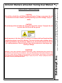
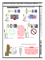
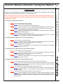
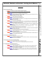
General guidelines for use Statement of purpose Equipment capacity Installation Set-up guide Operation Step-by-step operating procedure Troubleshooting Maintenance PM guide and schedule Proper lubricants and fastener tor ques Recommended spare parts Service information Care and maintenance documentation page Manufacturer’s declaration Mandrel operation Assembly drawings, spare parts lists & wiring diagrams 1 Schlumpf USA Stacker Tooling User Manual Page Schlumpf, Inc., 39 Enterprise Drive, Windham, Maine 04062 U.S.A. Tel: 207-893-1903. Fax: 207-893-1905. Internet: www.schlumpf-inc.com. www.armanni-usa.com. E-mail: [email protected] Armanni Stackers w/Custom Tooling User Manual General Guidelines On The Use Of Schlumpf Material Handling Equipment General: Thank you for choosing to use Schlumpf material handling equipment for your handling applications and needs. All Schlumpf machinery is proudly designed, manufactured, assembled, and tested in the U.S.A. This information is intended for use and review by maintenance and operating personnel before the equipment is operated or maintenance is performed. Schlumpf material handling equipment is high-value machinery and should be used and maintained with care. Please read these instructions carefully! Safety: All equipment must be operated by trained personnel. Never touch any rotating machinery or machine parts until movement has completely stopped. Damage or injury may result! Lifting Capacity / Permissible Use under Load: Maximum load allowances have been calculated for this equipment based upon operating data supplied to Schlumpf at the time of order. Maximum load values refer to the maximum weight of the material to be handled. Never exceed the maximum allowable load value for this equipment. Consult Schlumpf before using this equipment in any other application for which it was not originally intended. Damage or injury may result! Schlumpf material handling machines are intended to lift, lower, insert, extract, and position rolls or other forms of material. The machine is not intended to lift material over the specified design weights supplied to Schlumpf at the time of order. Damage to the machine or operator injury may result! Plant / Workplace Conditions and Operation: Machinery with which this Schlumpf equipment will be used should be in good repair and properly aligned (spindle to spindle axis, web path axis, etc.). Misalignment will cause adverse affects that may hamper desired operation and will increase the rate of wear of Schlumpf and other equipment. Page 2 Schlumpf, Inc., 39 Enterprise Drive, Windham, Maine 04062 U.S.A. Tel: 207-893-1903. Fax: 207-893-1905. Internet: www.schlumpf-inc.com. www.armanni-usa.com. E-mail: [email protected] Armanni Stackers w/Custom Tooling User Manual To assure safe and proper operation of this and other equipment, follow preventative maintenance guidelines set forth in this manual* and any additional instructions prescribed by the manufacturer of the equipment on which your Schlumpf product will be used. Periodically check screws and bolts for proper tightness as fasteners can loosen due to vibration. This product should be kept clean and free of foreign matter. Replace any and all damaged parts immediately. * Warranty claims can not be accepted unless proof of periodic maintenance (according to the guidelines set forth in this manual) can be furnished by the user. Lubrication: For lubrication of moving or gliding surfaces we recommend the use of a high quality grease such as JetLube Clear-Clean Lubricant with PTFE. If alternative products are used it is important that they meet the following requirements: high adhesion of the lubricant, high and permanent lubricate under load, little or no attraction of dust, contains no dangerous or hazardous propellants, gases, or ingredients that may be harmful to the environment or operators. Schlumpf, Inc. Maintenance and Warranty: Service and maintenance should be performed only by trained personnel following the guidelines established in this installation, operation, and maintenance manual. Damage or injury may result if established procedures are not followed! Please consult Schlumpf with any questions or problems you may have with this or any other Schlumpf equipment. Spare Parts And Tools: Use only Schlumpf spare and replacement parts or those recommended by Schlumpf. Use of any other parts will void your product warranty! Tools, metric fasteners, metric components, or any other special related items required for the maintenance of Schlumpf equipment are available from Schlumpf. Transport Damage: Schlumpf equipment is thoroughly tested and carefully packaged prior to shipment. If your unit was damaged in transport, contact the shipper immediately. Make sure that you contact the transporter within 24 hours of the receipt of the machine and, preferably, do not sign a receipt for the machine without noting the damage on the bill of lading. Call Schlumpf immediately! Do not try to operate the equipment. Damaged parts which have not been reported immediately to Schlumpf will not be replaced under warranty. Equipment and Operating Safety: This equipment was manufactured in accordance with the acknowledged regulations of the technology involved and has been thoroughly tested under load. Before placing the unit into service, check for possible transport damage and review this manual with all potential operators of the equipment. Thoroughly test the equipment unloaded before attempting to handle any kind of load. Follow these guidelines for operating safety: "WARNING" Never step under or stand under suspended loads. In principle, the operator stands behind or to the side of the unit, never to the front. Only the operator should remain within the working radius of the equipment. Always work within the permissible load capacity of the Schlumpf equipment and hoist system. Only allow trained maintenance personnel to service and repair the equipment. Use only Schlumpf accessories and spare parts. Always unload the equipment before lowering the unit to the floor or taking the unit out of service. Never exceed Schlumpf capacities for maximum roll or material weight and dimensions. Schlumpf equipment is designed to lift material only. Never lift personnel. Operators and personnel should never stand or ride on the machine. The maximum load capacity of all Schlumpf equipment is clearly labeled on the machine itself. Never exceed the load capacity of the unit. Damage, extreme wear and operator injury may result. Closely follow the recommendations and instructions of the manufacturer of purchased system components. Failure to do so can result in equipment damage and/or serious operator injury! 3 Schlumpf, Inc. Service: Page Schlumpf, Inc., 39 Enterprise Drive, Windham, Maine 04062 U.S.A. Tel: 207-893-1903. Fax: 207-893-1905. Internet: www.schlumpf-inc.com. www.armanni-usa.com. E-mail: [email protected] Armanni Stackers w/Custom Tooling User Manual Schlumpf material handling equipment has been designed to operate as mechanical lifting, turning and positioning devices for the handling of materials in a horizontal and / or vertical orientation. Schlumpf hoist-based equipment is for use with cranes and overhead hoists within the operating perimeter of the material handling plant or workspace and may be used only for this purpose. The hoist or crane on which Schlumpf hoist-based material handling equipment is used should have the capability of being rendered inoperable with an Emergency stop switch. Schlumpf portable / floor-based equipment is for use within the operating perimeter of the material handling plant or workspace with a solid concrete or comparable floor and may be used only for this purpose. Consult Schlumpf if the unit is to be used with materials other than rolled (cored) materials, or other than what the equipment was originally specified and designed. Schlumpf standard mandrels are designed to handle materials with a paper/cardboard core. If the core of the material to be handled has been changed or is not paper/cardboard, special modifications to the grippers must be made. This includes, but is not limited to, steel, plastic and aluminum cores. Schlumpf mechanically expanding mandrels are “fail safe”, self tightening, and can only be disengaged from the core by the operator. CAUTION! Schlumpf material handling equipment is for use under operating conditions supplied to Schlumpf at the time of order. As such, it may not be possible to safely use the machine for any conditions beyond the stated capacities and specifications. Please consult Schlumpf when a change in operating parameters may affect the unit’s safe and proper use. Schlumpf equipment has been clearly labeled with warning and informational signs. For your safety, read and obey all labeling on your machine. Load capacity, when handling and manipulating a rolled/cored bundle of material, is a function of roll weight vs. roll face width. A load capacity curve has been generated for most Schlumpf handling equipment and is located on the capacity page for the specific equipment pertaining to this manual. Do not exceed maximum capacity! Serious injury or equipment damage will result! 4 Schlumpf, Inc. Statement Of Purpose Page Schlumpf, Inc., 39 Enterprise Drive, Windham, Maine 04062 U.S.A. Tel: 207-893-1903. Fax: 207-893-1905. Internet: www.schlumpf-inc.com. www.armanni-usa.com. E-mail: [email protected] Armanni Stackers w/Custom Tooling User Manual Equipment Specifications And Capacities The capacity for the stacker tooling is clearly labeled on the unit itself. Examples of capacity label and chart on Armanni unit Refer to Stacker User manual for operating the stacker unit Power Source: (2) 12 volt DC sealed lead-acid batteries in series for 24 volt DC output or 24 VDC wet cell traction batteries. Operating Controls: Push buttons or precision hydraulic lever valves. Power Transmission for Toolings: Electric linear actuators, hydraulic cylinders DO NOT OVERCLUTCH ACTUATORS! ELECTRIC ACTUATORS ARE EQUIPPED WITH A SLIP CLUTCH FOR REACHING END-OF-STROKE. DO NOT LET ACTUATOR CLUTCH RATCHET CONTINUOUSLY. OVERCLUTCHING ELECTRIC ACTUATORS WILL CAUSE PREMATURE WEAR AND DAMAGE! Page 5 Schlumpf, Inc., 39 Enterprise Drive, Windham, Maine 04062 U.S.A. Tel: 207-893-1903. Fax: 207-893-1905. Internet: www.schlumpf-inc.com. www.armanni-usa.com. E-mail: [email protected] Armanni Stackers w/Custom Tooling User Manual The Schlumpf tooling is clearly labeled with a load capacity sticker. Do not exceed the maximum roll weight. Serious injury or equipment damage will result! Example of capacity label and chart on Schlumpf unit*: (*actual weight, width and diameter capacities will vary!) Schlumpf, Inc. * Batteries not covered under warranty CAUTION! Do not lift a roll with the roll OR the tooling off-center. Doing so may cause the roll or machine to become unstable, possibly resulting in product damage, injury or death! CAUTION! Do not transport the roll when the roll is at the top of the column. Transport the roll no more than 24”(61cm) off the ground. Avoid exposure to the laser light. The stacker is equipped with an Operational Hazard-Semiconductor Laser Diode Module. This laser module emits radiation that is visible and harmful to the human eye. When in use, do not look directly into the laser emitting aperture. Direct viewing of laser diode emission at close range may cause eye damage. CAUTION! Damaged or worn parts should be replaced immediately! Many Schlumpf parts have specific surface treatment and especially heat treatment. Use only Schlumpf spare and replacement parts. Failure to do so may result in damage to the equipment or process! Never alter tooling or lift carriage parts without first consulting Schlumpf. Damage or injury may result. Always unplug the power cables before servicing Schlumpf machines. 6 Schlumpf, Inc. General Stacker Cautions/Warnings Page Schlumpf, Inc., 39 Enterprise Drive, Windham, Maine 04062 U.S.A. Tel: 207-893-1903. Fax: 207-893-1905. Internet: www.schlumpf-inc.com. www.armanni-usa.com. E-mail: [email protected] Armanni Stackers w/Custom Tooling User Manual Armanni Stackers w/Custom Tooling User Manual Page General Stacker Operation Schlumpf, Inc., 39 Enterprise Drive, Windham, Maine 04062 U.S.A. Tel: 207-893-1903. Fax: 207-893-1905. Internet: www.schlumpf-inc.com. www.armanni-usa.com. E-mail: [email protected] Refer to Stacker User manual for operating the stacker unit Tooling function pushbuttons on tiller “Lift”, “Lower”, drive, and tooling function levers and buttons located on stacker top panel Example All operators should become familiar with the controller buttons and functions prior to operating the unit in service. Schlumpf, Inc. Functions of the tooling are controlled with handheld controller, control box, tiller buttons and/or the hydraulic levers, shown below. 7 1. 2. CAUTION! Always clamp the roll in the center. Do not clamp the roll so it is off center from the clamp (see above right). Failure to clamp the roll on center will result in equipment damage and / or personal injury! 3. Press the “clamp” function on the controls. Controls example CAUTION RELEASE THE CLAMP BUTTON WHEN THE ROLL IS SECURE IN THE CLAMP TOOLING. CONTINUING TO PRESS THE CLAMP BUTTON WILL CAUSE PREMATURE WEAR / DAMAGE TO THE CLAMP ACTUATORS! 8 Schlumpf, Inc. Operation (POD) & (OD-R): Clamping a roll in the vertical position Page Schlumpf, Inc., 39 Enterprise Drive, Windham, Maine 04062 U.S.A. Tel: 207-893-1903. Fax: 207-893-1905. Internet: www.schlumpf-inc.com. www.armanni-usa.com. E-mail: [email protected] Armanni Stackers w/Custom Tooling User Manual 1. 2. CAUTION! Always clamp the roll in the center. Do not clamp the roll so it is off center from the clamp (see above right). Failure to clamp the roll on center will result in equipment damage and / or personal injury! 3. Press the “clamp” function on the controls. Controls example CAUTION RELEASE THE CLAMP BUTTON WHEN THE ROLL IS SECURE IN THE CLAMP TOOLING. CONTINUING TO PRESS THE CLAMP BUTTON WILL CAUSE PREMATURE WEAR / DAMAGE TO THE CLAMP ACTUATORS! 9 Schlumpf, Inc. Operation (OD-R): Clamping a roll in the horizontal position Page Schlumpf, Inc., 39 Enterprise Drive, Windham, Maine 04062 U.S.A. Tel: 207-893-1903. Fax: 207-893-1905. Internet: www.schlumpf-inc.com. www.armanni-usa.com. E-mail: [email protected] Armanni Stackers w/Custom Tooling User Manual 1. 2. 3. Transport the roll to the desired location. CAUTION! Do not transport the roll when the roll is at the top of the column. Transport the roll no more than 12”(30cm) off the ground. The roll can be transported in the horizontal or vertical position. 10 Schlumpf, Inc. Operation (OD-R): Rotating a roll once it has been clamped. Page Schlumpf, Inc., 39 Enterprise Drive, Windham, Maine 04062 U.S.A. Tel: 207-893-1903. Fax: 207-893-1905. Internet: www.schlumpf-inc.com. www.armanni-usa.com. E-mail: [email protected] Armanni Stackers w/Custom Tooling User Manual Lift the roll with the unit and move it away from the pallet / stack from which it is being moved. Press the “counter-clockwise” button/lever on the handheld controller/control panel/control box. Rotate the roll to the core-horizontal position, as shown below. The tooling will stop at the intermediate sensor. Press the “down” button/lever on the handheld controller/control panel/control box. Lower the roll to the floor or until the roll is supported. Unclamp the roll from the clamp tooling. Press the “unclamp” and “unclamp enable” buttons/lever on the handheld controller/control panel/control box. Pull the unit away from the roll. 11 Schlumpf, Inc. Operation (cont’d) OD-R Page Schlumpf, Inc., 39 Enterprise Drive, Windham, Maine 04062 U.S.A. Tel: 207-893-1903. Fax: 207-893-1905. Internet: www.schlumpf-inc.com. www.armanni-usa.com. E-mail: [email protected] Armanni Stackers w/Custom Tooling User Manual Set-up (Mandrels) Mandrel installation Locking tab Locking thumb screw 1. Unlock the mandrel locking plate and slide the mandrel into the turner arm. Mandrel notch 2. With the mandrel neck inserted all the way in the turner arm, swing the locking plate around the mandrel neck, locking the locking tab in the notch at the top of the mandrel. 3. Lock the mandrel locking plate back in place with the locking thumb screw. Page 12 Schlumpf, Inc., 39 Enterprise Drive, Windham, Maine 04062 U.S.A. Tel: 207-893-1903. Fax: 207-893-1905. Internet: www.schlumpf-inc.com. www.armanni-usa.com. E-mail: [email protected] Armanni Stackers w/Custom Tooling User Manual Schlumpf, Inc. Locking thumb screw 1. Unscrew the locking thumb screw and slide or swing the mandrel plate to the open position. 2. Insert the mandrel into the turner arm. The toggle handle should be facing the front, as shown. 3. When the mandrel is fully inserted into the arm, slide the mandrel plate around the mandrel neck to lock it in place. Toggle handle 4. Screw the captive screw into the locking hole. The mandrel toggle handle should be facing forward and the toggle handle roller should be under the captive support on the mandrel plate. Toggle handle roller underneath captive support 13 Schlumpf, Inc. Set-up (Mandrels, toggle handle) Page Schlumpf, Inc., 39 Enterprise Drive, Windham, Maine 04062 U.S.A. Tel: 207-893-1903. Fax: 207-893-1905. Internet: www.schlumpf-inc.com. www.armanni-usa.com. E-mail: [email protected] Armanni Stackers w/Custom Tooling User Manual Limit switch adjustment The turner limit cam should be adjusted so the tooling turns a roll to the horizontal position. Set screw Loosen the set screw on the limit cam to adjust the position. Tighten the set screw onto the shaft when the cam has been adjusted. Adjust the turner limit cam clockwise to increase the horizontal travel. Adjust the limit cam counter-clockwise to decrease the horizontal travel. The roller plunger on the limit switch will drop onto the small diameter of the turner limit cam and stop the Roll should be horizontal travel. horizontal when turner stops This will need to be done when the unit is loaded, so it can be adjusted properly to position the roll horizontal. 14 Schlumpf, Inc. Set-up (PT5) Page Schlumpf, Inc., 39 Enterprise Drive, Windham, Maine 04062 U.S.A. Tel: 207-893-1903. Fax: 207-893-1905. Internet: www.schlumpf-inc.com. www.armanni-usa.com. E-mail: [email protected] Armanni Stackers w/Custom Tooling User Manual 1. Retract the mandrel grippers Grippers retracted 2. Keep the grippers retracted and insert the mandrel into a roll. Use the hydraulic levers to drive the tooling / mandrel down into the roll core TIP: Some tooling assemblies are designed to “float” a few degrees to assist in mandrel & core alignment. Tooling arm float— No actuator movement 1/4"(.6cm)1/2"(1.3cm) space TIP: Leave a small space (1/4"(.6cm)-1/2"(1.3cm)) between the roll face and roll handling device. This will help with the retraction of the grippers when the roll is set down and the mandrel is removed. CAUTION! Always transport the roll in the vertical position. Do not turn the roll to the horizontal position to transport. Transport the roll no more than 6-12”(15-30cm) off the ground. 15 Schlumpf, Inc. Operation (PT) Page Schlumpf, Inc., 39 Enterprise Drive, Windham, Maine 04062 U.S.A. Tel: 207-893-1903. Fax: 207-893-1905. Internet: www.schlumpf-inc.com. www.armanni-usa.com. E-mail: [email protected] Armanni Stackers w/Custom Tooling User Manual 5. Release the grippers when the mandrel is inserted properly into the core. Grippers expanded Transport the roll to the desired location. 6. After reaching the desired location of the roll, lift the roll as necessary or to the desired height. 7. Turn the roll to the horizontal position. Operate the handheld controller/control panel/control box on the unit. 8. Raise / lower the roll as desired and load the roll in the desired location, so it is fully and safely supported. 9. Retract the mandrel grippers. 16 Schlumpf, Inc. Operation (cont’d) Page Schlumpf, Inc., 39 Enterprise Drive, Windham, Maine 04062 U.S.A. Tel: 207-893-1903. Fax: 207-893-1905. Internet: www.schlumpf-inc.com. www.armanni-usa.com. E-mail: [email protected] Armanni Stackers w/Custom Tooling User Manual 1. Drive the unit to the roll that is to be handled. 2. Move the lift carriage up/down and side shift left/right so the probe is in line with the core of the roll. Roll MUST bump against tooling frame! 3. Drive the unit forward to insert the probe into the core of the roll. 4. Insert the probe into the core until the tooling of the Stacker unit bumps against the face of the roll. CAUTION! Never transport or lift roll when the roll is not fully engaged with the probe and up against the tooling frame! 17 Schlumpf, Inc. Operation (PH): Loading and Unloading a Roll Page Schlumpf, Inc., 39 Enterprise Drive, Windham, Maine 04062 U.S.A. Tel: 207-893-1903. Fax: 207-893-1905. Internet: www.schlumpf-inc.com. www.armanni-usa.com. E-mail: [email protected] Armanni Stackers w/Custom Tooling User Manual 5. Transport the roll to the desired location and load it so it is fully and safely supported. 6. Once the load is fully supported, lower the probe slightly to relieve it of the load. 7. Extract the probe from the core by reversing the Stacker unit straight back. CAUTION! Do not transport the roll when the roll is at the top of the column. Transport the roll no more than 24”(61cm) off the ground. 18 Schlumpf, Inc. Operation (PH, cont’d) Page Schlumpf, Inc., 39 Enterprise Drive, Windham, Maine 04062 U.S.A. Tel: 207-893-1903. Fax: 207-893-1905. Internet: www.schlumpf-inc.com. www.armanni-usa.com. E-mail: [email protected] Armanni Stackers w/Custom Tooling User Manual The coupling receivers must be mounted to all spindles. Drill and tap 1/2-13 UNC hole on center of all spindles for receiver mounting. The sensor couplings will be factory set to properly engage with the spindle couplings. If any further adjustment is needed, see below. Remove the coupling from the probe by removing the fasteners. Slide the coupling out of the probe. If equipped, adjust the probe sensor switch by threading it into or out of the probe coupling. Threading it further into the coupling will decrease the sensitivity. Threading it out of the coupling will increase the sensitivity. ALWAYS TEST THE UNITS UNLOADED BEFORE PLACING THEM INTO SERVICE! 19 Schlumpf, Inc. Set-up (PH) Page Schlumpf, Inc., 39 Enterprise Drive, Windham, Maine 04062 U.S.A. Tel: 207-893-1903. Fax: 207-893-1905. Internet: www.schlumpf-inc.com. www.armanni-usa.com. E-mail: [email protected] Armanni Stackers w/Custom Tooling User Manual Schlumpf recommends marking the floor at each spindle for proper loader alignment. Engage the unit with the spindle coupling at each spindle and mark the floor as need with guide lines. This will increase production efficiency and reduce wear and damage to the unit. Floor Markings 20 Schlumpf, Inc. Set-up (cont’d) Page Schlumpf, Inc., 39 Enterprise Drive, Windham, Maine 04062 U.S.A. Tel: 207-893-1903. Fax: 207-893-1905. Internet: www.schlumpf-inc.com. www.armanni-usa.com. E-mail: [email protected] Armanni Stackers w/Custom Tooling User Manual All functions of the unit will be controlled with the hydraulic levers, control pendants, tiller control buttons, and/or control box buttons. All operators should become familiar with the control buttons and functions prior to operating the unit in service. 1. Raise / lower the probe tooling to the proper height and push the unit forward into the core of a roll. 2. Insert the probe into the roll all the way so the roll face bumps against the roll push plate. 21 Schlumpf, Inc. Operation (PH) Page Schlumpf, Inc., 39 Enterprise Drive, Windham, Maine 04062 U.S.A. Tel: 207-893-1903. Fax: 207-893-1905. Internet: www.schlumpf-inc.com. www.armanni-usa.com. E-mail: [email protected] Armanni Stackers w/Custom Tooling User Manual 3. Raise the unit to the maximum height or to a height that will easily clear the spindle to be loaded. Use the hydraulic levers to drive the tooling and roll up. 4. Drive the unit to the marks on the floor for proper coupling alignment. Step to the front of the unit to check that the spindle and coupling are aligned. 5. Lower the probe towards the spindle coupling. Use the hydraulic levers to drive the tooling and roll down. 6. Drive the unit down until the coupling engages with the spindle. The down function will automatically stop when the coupling is engaged, via the sensor. 22 Schlumpf, Inc. Operation (cont’d) Page Schlumpf, Inc., 39 Enterprise Drive, Windham, Maine 04062 U.S.A. Tel: 207-893-1903. Fax: 207-893-1905. Internet: www.schlumpf-inc.com. www.armanni-usa.com. E-mail: [email protected] Armanni Stackers w/Custom Tooling User Manual 7. Transfer the roll from the probe to the spindle with the roll pusher. Use the buttons/levers on the handheld controller/control panel/control box to extend the tooling. DO NOT ATTEMPT to operate pusher unless properly engaged. DO NOT OVERCLUTCH ACTUATORS! ELECTRIC ACTUATORS ARE EQUIPPED WITH A SLIP CLUTCH FOR REACHING END-OF-STROKE. DO NOT LET ACTUATOR CLUTCH RATCHET CONTINUOUSLY. OVERCLUTCHING ELECTRIC ACTUATORS WILL CAUSE PREMATURE WEAR AND DAMAGE! 8. Retract the pusher when the roll is completely transferred onto the spindle. Use the buttons/levers on the handheld controller/control panel/control box to retract the tooling. The pusher will function only when the spindle coupling is properly engaged. 9. Raise the tooling and probe to disengage the sensor coupling. Use the hydraulic levers to drive the tooling up. 10. Pull the unit away from the spindle. Lower the probe tooling if desired by using the hydraulic levers. 23 Schlumpf, Inc. Operation (cont’d) Page Schlumpf, Inc., 39 Enterprise Drive, Windham, Maine 04062 U.S.A. Tel: 207-893-1903. Fax: 207-893-1905. Internet: www.schlumpf-inc.com. www.armanni-usa.com. E-mail: [email protected] Armanni Stackers w/Custom Tooling User Manual 1. 2. 4. CAUTION! Do not lift a roll with the roll OR the tooling off-center. Doing so may cause the roll or machine to become unstable, possibly resulting in product damage, injury or death! 3. 24 Schlumpf, Inc. Operation (PV90): Loading and Unloading a Roll Page Schlumpf, Inc., 39 Enterprise Drive, Windham, Maine 04062 U.S.A. Tel: 207-893-1903. Fax: 207-893-1905. Internet: www.schlumpf-inc.com. www.armanni-usa.com. E-mail: [email protected] Armanni Stackers w/Custom Tooling User Manual “Clamp” and “Unclamp” functions of the shaft handling tooling are controlled either from the Stacker control handle bar, shown to the left, OR on a handheld controller/ stacker cabinet, shown below. Refer to Stacker User manual for operating the stacker unit “Clamp” & “Unclamp” tooling function pushbuttons on Stacker handle bar All operators should become familiar with the controller buttons and functions prior to operating the unit in service. “Lift”, “Lower”, and drive functions located on stacker handle bar and control panel “Clamp” & “Unclamp” tooling function pushbuttons on stacker control box and/ or tiller. For stackers equipped with laser alignment the “Laser” is turned on by pushbutton on the control box or tiller. 25 Schlumpf, Inc. Operation (Shaft Handling) Page Schlumpf, Inc., 39 Enterprise Drive, Windham, Maine 04062 U.S.A. Tel: 207-893-1903. Fax: 207-893-1905. Internet: www.schlumpf-inc.com. www.armanni-usa.com. E-mail: [email protected] Armanni Stackers w/Custom Tooling User Manual If equipped, press the “Laser” key on the handheld controller/control panel/control box to activate the laser. The laser will make an X when activated. See below for correct alignment. The laser is attached to a steel plate which is adjustable. Adjust the position of the laser to the size shaft(s) you may have. TIP: Align laser just below centerline to clear anvil Laser WARNING Avoid exposure to the laser light. The stacker is equipped with an Operational HazardSemiconductor Laser Diode Module. This laser module emits radiation that is visible and harmful to the human eye. When in use, do not look directly into the laser emitting aperture. Direct viewing of laser diode emission at close range may cause eye damage. If the ESH tooling is supplied with multiple shaft support anvils, select the appropriate anvil for the shaft that is to be handled and place it on the front anvil support of the tooling. The spare anvil should be stored on the bracket shown. Spare anvil bracket Front anvil support and active bracket 26 Schlumpf, Inc. Operation (cont’d) Page Schlumpf, Inc., 39 Enterprise Drive, Windham, Maine 04062 U.S.A. Tel: 207-893-1903. Fax: 207-893-1905. Internet: www.schlumpf-inc.com. www.armanni-usa.com. E-mail: [email protected] Armanni Stackers w/Custom Tooling User Manual Extracting a shaft: 1. Drive the unit toward the shaft that is to be extracted. 2. Raise / lower the carriage and tooling so the shaft support anvils are just under the shaft journal end. Press the “up” or “down” buttons/levers on the handheld controller/control panel/control box. 3. Drive the unit forward so the shaft anvils line up with the designated journal features onto which the clamp tooling will clamp. Anvils should align with journal features (The designated journal features on which to clamp are specified during design approval.) 4. Raise tooling up underneath shaft. If equipped, shaft presence sensor will limit upward travel when shaft is in the correct position (blue light). 5. Clamp the end of the journal shaft with the powered clamp tooling. The clamp actuator clutch may ratchet a couple of times when the shaft if fully clamped. Do not over-clutch the clamp actuator! On units equipped w/hydraulic shaft clamping, the green “shaft clamped” indicator will illuminate when the shaft is clamped. Press the “Clamp” buttons/levers on the handheld controller/control panel/control box. DO NOT OVERCLUTCH ACTUATORS! ELECTRIC ACTUATORS ARE EQUIPPED WITH A SLIP CLUTCH FOR REACHING END-OF-STROKE. DO NOT LET ACTUATOR CLUTCH RATCHET CONTINUOUSLY. OVERCLUTCHING ELECTRIC ACTUATORS WILL CAUSE PREMATURE WEAR AND DAMAGE! 27 Schlumpf, Inc. Operation (cont’d) Page Schlumpf, Inc., 39 Enterprise Drive, Windham, Maine 04062 U.S.A. Tel: 207-893-1903. Fax: 207-893-1905. Internet: www.schlumpf-inc.com. www.armanni-usa.com. E-mail: [email protected] Armanni Stackers w/Custom Tooling User Manual 5. When the shaft is fully clamped in the powered clamp tooling, extract the shaft from the core by driving the unit away from the roll. 6. When the shaft is fully extracted it may be transported to the desired location. CAUTION! TRANSPORT THE SHAFT AT A SAFE CENTERLINE HEIGHT. IF THE SHAFT IS EXTRACTED FROM A CORE THAT IS HIGH OFF THE GROUND, LOWER THE TOOLING BEFORE TRANSPORTING THE SHAFT! Press the “Down” button/levers on the handheld controller/control panel/control box 28 Schlumpf, Inc. Operation (cont’d) Page Schlumpf, Inc., 39 Enterprise Drive, Windham, Maine 04062 U.S.A. Tel: 207-893-1903. Fax: 207-893-1905. Internet: www.schlumpf-inc.com. www.armanni-usa.com. E-mail: [email protected] Armanni Stackers w/Custom Tooling User Manual Armanni Stackers w/Custom Tooling User Manual 29 Inserting a shaft: 1. With a shaft loaded in the clamp tooling, drive the unit toward the roll into which the shaft will be inserted. 2. Raise / lower the carriage and tooling so the shaft lines up with the core of the roll. Press the “up” or “down” buttons/levers on the handheld controller/control panel/control box. 3. Insert the shaft into the core of the roll by driving the unit forward. Schlumpf, Inc. Schlumpf, Inc., 39 Enterprise Drive, Windham, Maine 04062 U.S.A. Tel: 207-893-1903. Fax: 207-893-1905. Internet: www.schlumpf-inc.com. www.armanni-usa.com. E-mail: [email protected] Operation (cont’d) Page 4. Insert the shaft into the core as far as desired. 5. Release the journal end from the clamp tooling by raising the powered clamp off the shaft journal. Press the “Unclamp” and “Enable” button on the buttons/levers on the handheld controller/control panel/control box. 6. Lower the carriage and tooling a small amount so the shaft support anvils are disengaged from the shaft journal. Press the “Down” buttons/levers on the handheld controller/control panel/control box. 7. Drive the unit away from the roll and shaft, leaving the shaft in the core of the roll. 30 Schlumpf, Inc. Operation (cont’d) Page Schlumpf, Inc., 39 Enterprise Drive, Windham, Maine 04062 U.S.A. Tel: 207-893-1903. Fax: 207-893-1905. Internet: www.schlumpf-inc.com. www.armanni-usa.com. E-mail: [email protected] Armanni Stackers w/Custom Tooling User Manual 1. 2. 3. 5. 6. 4. Example Controls 7. 9. 8. Example Controls 6-12” (15-30cm) MAX Schlumpf, Inc. Operation (PSC) Schlumpf, Inc., 39 Enterprise Drive, Windham, Maine 04062 U.S.A. Tel: 207-893-1903. Fax: 207-893-1905. Internet: www.schlumpf-inc.com. www.armanni-usa.com. E-mail: [email protected] Armanni Stackers w/Custom Tooling User Manual Page 31 10. 1. 2. 4. 3. Example Controls 5. 6. Example Controls 7. 8. 6-12” (15-30cm) MAX Schlumpf, Inc. Operation (PC) Schlumpf, Inc., 39 Enterprise Drive, Windham, Maine 04062 U.S.A. Tel: 207-893-1903. Fax: 207-893-1905. Internet: www.schlumpf-inc.com. www.armanni-usa.com. E-mail: [email protected] Armanni Stackers w/Custom Tooling User Manual Page 32 Please refer to the following list of potential problems and their solutions if the equipment is not functioning normally before calling Schlumpf. We'll ask you the same questions! Note: Continual misuse of this product will cause extreme wear and increase the potential for operator injury. Units damaged in this manner should be removed from service immediately and returned to Schlumpf for repair. 1. The tooling / side shift will not operate: Dilemma: the power switch is in the “OFF” position. Solution: turn the switch to the “ON” position. Dilemma: there is a loose wire connection inside the control enclosure. Solution: remove the unit from service. A trained electrical technician should open and inspect the tooling control enclosure for any loose wire connections and reconnect them as necessary. Dilemma: there is an obstruction blocking the travel of the side shift. Solution: remove the obstruction from the unit and clean and lubricate the unit before performing any new operations with the loader. Dilemma: The roll is above the rated capacity of the unit. Solution: DO NOT attempt the handle a roll that is greater than the capacity of the unit. Contact Schlumpf, Inc. if there has been a change to the application / roll specs. 2. The mandrel will not engage with a roll in the vertical position: Dilemma: the mandrel is not in a vertical position. Solution: Jog the “Horizontal” / “Vertical” buttons on the handheld controller until the mandrel is vertical. Use the Bull’s eye level indicators located on the turner arm. Dilemma: the mandrel grippers are not retracted. Solution: Retract the mandrel grippers. Keep the grippers in the retracted position while engaging the mandrel with the core of a roll. 3. The mandrel will not engage with a roll in the horizontal position: Dilemma: the mandrel is not in a horizontal position. Solution: Adjust the horizontal limit switch cam so the tooling stops the mandrel in the horizontal position. Use the Bull’s eye level indicators located on the turner arm. Dilemma: the mandrel grippers are not retracted. Solution: Retract the mandrel grippers. Keep the grippers in the retracted position while engaging the mandrel with the core of a roll. 4. The powered clamp tooling will not clamp onto a journal end: Dilemma: the clamp and support anvils are not positioned correctly with the shaft journal. Solution: Refer to the spec drawing in the back of this manual to determine the correct features on the journal end on which to clamp. Move the unit forward or backward according to the position of the journal end in the tooling. Dilemma: shaft support anvils are incorrectly positioned in the clamp tooling. Solution: switch the positions of the plastic support anvils, as they are quick-change and may have been reversed in position. In most cases the anvil with the bigger “V” groove will be in the front of the tooling. Dilemma: the journal end is too small to be clamped in the powered clamp. Solution: Review the application notes, shaft specs, and design approval drawings and contact Schlumpf if there is a discrepancy between the design and the shaft that is to be handled. In most cases Schlumpf will be able to manufacture new support anvils to correctly support and clamp the shaft journal end. 33 Schlumpf, Inc. Troubleshooting Page Schlumpf, Inc., 39 Enterprise Drive, Windham, Maine 04062 U.S.A. Tel: 207-893-1903. Fax: 207-893-1905. Internet: www.schlumpf-inc.com. www.armanni-usa.com. E-mail: [email protected] Armanni Stackers w/Custom Tooling User Manual 5. The unit will not lift a load: Dilemma: the batteries are carrying insufficient voltage (see below). Pendant control functions will turn off when battery voltage drops too low! Solution: remove the loader from service and charge batteries. Dilemma: a wire has become loose or damaged inside the control box. Solution: remove the loader from service. A trained electrical technician should open the control enclosure and replace and loose / damaged wires. Dilemma: the power switch is in the “OFF” position. Solution: turn the switch to the “ON” position. Dilemma: there is an obstruction blocking the lifting screw Solution: remove the obstruction from the unit. Thoroughly clean all electro-mechanical components and their surroundings. Dilemma: the lift screw is at the end of its stroke. Solution: do not try to lift the load any higher. Do not continuously over-clutch the lift actuator! Contact the sales department at Schlumpf, Inc. if the application requires an extended lift height. Dilemma: the load is exceeding the capacity of the unit. Solution: Do not attempt to lift a load that exceeds the capacity of the unit. Damage to the lift motor will occur. Contact the sales department at Schlumpf, Inc. if the application requires a greater lift capacity. Dilemma: the thermal overload protection has momentarily cut power to the lift motor. This is due to continuous loading without adhering to the duty cycle (see below). Solution: Stop use of the unit for at least 10-15 minutes. The thermal overload will automatically reset when the motor cools down. Dilemma: the motor overload has tripped and cut power to the lifting motor. Solution: remove the loader from service. A trained electrical technician should open the control enclosure and reset the overload. Dilemma: there is an obstruction blocking the photo-optic sensor(s) Solution: remove the obstruction from the unit and wait for the time delay to complete before performing any new operations with the loader. 6. The unit will not properly release a roll: Dilemma: the turner tooling is not horizontal or vertical. Solution: jog the turner tooling so the turner is vertical or horizontal. Use the bull’s eye levels provided on the turner arm for assistance. 7. The unit will not turn a roll to horizontal position: Dilemma: the turner horizontal limit switch is not adjusted correctly. Solution: refer to the “Set-up” section for properly adjusting the turner limit switch. 8. The mandrel will not disengage from a roll: Dilemma: the roll is not properly supported. Solution: Jog the “Horizontal” / “Vertical” and “Up” / “Down” buttons on the handheld controller until the roll is fully supported. Mandrel gripper will not easily retract if still supporting a load. Dilemma: the roll core and mandrel are not aligned. Solution: Jog the “Horizontal” / “Vertical” and “Up” / “Down” buttons on the handheld controller until the roll and mandrel are aligned. With floating tooling, the tooling will begin to float when the mandrel and roll are aligned. 34 Schlumpf, Inc. Troubleshooting Page Schlumpf, Inc., 39 Enterprise Drive, Windham, Maine 04062 U.S.A. Tel: 207-893-1903. Fax: 207-893-1905. Internet: www.schlumpf-inc.com. www.armanni-usa.com. E-mail: [email protected] Armanni Stackers w/Custom Tooling User Manual Generally, Schlumpf handling equipment is maintenance free. However, all mechanical equipment should be inspected periodically for safety, proper function, lubrication, and wear. This care will ensure years of trouble-free performance from Schlumpf equipment. The check should be performed by trained maintenance personnel and a written record of the inspection should be maintained in accordance with regulations covering “load lifting devices”. A tabulated page is located in this manual for keeping care and maintenance records. Schlumpf will, for a nominal fee, perform the inspection and submit a written report on all services. Contact Schlumpf for further information. All Schlumpf products should be Cared for According to this schedule*: DAILY: Inspect the loader for worn, damaged, or missing parts & fasteners. Inspect the normal operation: The side shift operate smoothly through the entire range. The turner operates smoothly through the entire range. The hard stops stop the travel of the side shift. Carriage MONTHLY: (remove unit from service) Lubricate all moving parts and linear motion components. Side shift screw Linear bearings Actuator / turner arm pivot point All other metal-on-metal moving components Disconnect power to the control box. Open control enclosure and inspect for loose / damaged wires and components. This should only be performed by a trained electrical technician. Check all fasteners on the unit and tighten to the proper torque if loose. * Schedule is based on one shift per day. The time intervals between service may need to be reduced, depending on the amount of use and the environmental conditions present in your application (i.e., a machine used in a dusty environment may need to be cleaned and lubricated more often). 35 Schlumpf, Inc. Periodic Maintenance Page Schlumpf, Inc., 39 Enterprise Drive, Windham, Maine 04062 U.S.A. Tel: 207-893-1903. Fax: 207-893-1905. Internet: www.schlumpf-inc.com. www.armanni-usa.com. E-mail: [email protected] Armanni Stackers w/Custom Tooling User Manual Fastener torque Fasteners should always be installed to their proper tightening torque. The table below shows the recommended tightening torques for standard metric screws. Size Torque (N-m) Torque (lb-in) M4 x 0.7 5.8 52 M5 x 0.8 12 106 M6 x 1.0 20 179 M8 x 1.25 49 430 M10 x 1.5 97.5 863 M12 x 1.75 165 1460 M16 x 2.0 412 3650 Lubricants & Thread locking fluids Schlumpf recommends the following compounds & fluids or their equivalent be used to provide care and maintenance for the Schlumpf turner and side shift tooling: Lifting screw & linear bearing lubricant Metal-on-metal lubricant Jet-Lube Clear-Clean Lubricant with PTFE 36 Motorex Universal 2000 spray lubricant Fastener thread locking Loctite 242 (Blue) medium-duty threadlocker CAUTION! Damaged or worn parts should be replaced immediately! Many Schlumpf parts have specific surface treatment and especially heat treatment. Use only Schlumpf spare and replacement parts. Failure to do so may result in damage to the equipment or process! Never alter tooling or lift carriage parts without first consulting Schlumpf. Damage or injury may result. Always unplug the power cables before servicing Schlumpf machines. Schlumpf, Inc. Page Schlumpf, Inc., 39 Enterprise Drive, Windham, Maine 04062 U.S.A. Tel: 207-893-1903. Fax: 207-893-1905. Internet: www.schlumpf-inc.com. www.armanni-usa.com. E-mail: [email protected] Armanni Stackers w/Custom Tooling User Manual Spare parts lists, assembly specifications, and in the case of units with integral controls, wiring diagrams, are attached to the back of this manual for the Roll Handling Tooling. Copies of the spare parts list are available upon request. Recommended spare parts to be kept on hand, per unit, are indicated on the spare parts list drawings in the back of the manual. They have an asterisk at the end of the part number. Example: P-10186* Crank handle Service Information: To arrange for service on any Schlumpf roll handling devices, contact Schlumpf at the following address: Schlumpf, Inc. 39 Enterprise Drive Windham, Maine 04062-5650 U.S.A. Tel: 207-893-1903 Fax: 207-893-1905 E-mail: [email protected] Internet: www.schlumpf-inc.com Be prepared to supply the following information: 1. 2. 3. 4. 5. 6. 7. Handling unit Serial No. (M-XXXXX). Description of service required or nature of problem. Original Purchase Order No. Schlumpf Invoice or Sales Order No. Date of purchase. Your name, address, telephone No. , fax No. or other contact information. Purchase Order for service. 37 Schlumpf, Inc. Recommended spare parts Page Schlumpf, Inc., 39 Enterprise Drive, Windham, Maine 04062 U.S.A. Tel: 207-893-1903. Fax: 207-893-1905. Internet: www.schlumpf-inc.com. www.armanni-usa.com. E-mail: [email protected] Armanni Stackers w/Custom Tooling User Manual Desription of Care / Maintenance Performed: Date Performed: Maintenance Performed by: Schlumpf, Inc. Notes & Maintenance Records: Schlumpf, Inc., 39 Enterprise Drive, Windham, Maine 04062 U.S.A. Tel: 207-893-1903. Fax: 207-893-1905. Internet: www.schlumpf-inc.com. www.armanni-usa.com. E-mail: [email protected] Armanni Stackers w/Custom Tooling User Manual Page 38 Manufacturer and Distributor: Schlumpf, Inc. 39 Enterprise Drive, Suite 1 Windham, Maine 04062-5649 U.S.A. Tel: 207-893-1903 Fax: 207-893-1905 E-mail: [email protected] Internet: www.schlumpf-inc.com Declares that this Schlumpf-type material handling tooling unit has been designed and manufactured according to known engineering and safety specification and regulations. This unit was made in the U.S.A. with materials and components known to be of high quality. The use of the equipment is governed by local, sate and federal safety regulations. Warranty Statement: Seller warrants that the products sold will be free of defects in material and workmanship for a period of one year (365 days) when used on a one shift per day (not more than eight hours) basis, six months (180 days) when used on a two or three shift per day (more than eight hours) basis, from the date of delivery unless otherwise specified on the face of this document. This warranty is limited by the paragraphs below. If buyer discovers a defect in any of the products covered by this Agreement, Buyer's exclusive remedy shall be to notify Seller immediately of such defect, and Seller,, at its option, will repair or replace the Products, or refund the purchase price. Said notice shall be in writing and shall contain pertinent information to permit Seller to identify the Product which is claimed to be defective, including without limitation, the product type and serial number and a full description of the circumstances giving rise to the claim. Failure to properly notify Seller within warranty period of such defects or Buyers undertaking or authorizing others to undertake remedial action without Seller's express approval in writing shall immediately invalidate Seller's warranty obligations. Upon timely receipt of proper notice, Seller shall inform Buyer of the remedial action which it intends to take, and if return of the product is elected by Seller, Seller will provide Buyer with a Return Authorization Number. Buyer must comply with Seller's shipment instructions (see paragraph below) and ship the defective Product immediately. Seller reserves the right to reject any warranty claim not properly reported and any warranty claim on any item that has been the subject of abuse, misuse, neglect, improper installation or repair, alteration, modification, accident, improper return handling, use in or with equipment not suitable for such use, unusual physical, electrical, electro-magnetic stress, failure of electric power, external causes affecting the Product, or other factors which are not covers by the warranty. Buyer must pay freight costs to Seller for returned Products. Buyer's packaging list must show the Return Authorization Number, invoice number, date and list of all returned goods. The carton must also show the Return Authorization Number. Seller will pay return freight to the Buyer and reimburse Buyer for its reasonable return freight costs for products which are subject to warranty adjustment. There is no other charge for warranty adjustment during the warranty period, When Buyer returns any Product, Buyer shall be responsible for all damage resulting from improper packing or handling and for loss in transit notwithstanding any defect or nonconformity in the Product. If it is found that a warranty adjustment is not available for any defect claimed by Buyer, for any reason, Buyer will be notified and the product will be returned at Buyer's expense. 49 Schlumpf, Inc. Manufacturer's Declaration: Page Schlumpf, Inc., 39 Enterprise Drive, Windham, Maine 04062 U.S.A. Tel: 207-893-1903. Fax: 207-893-1905. Internet: www.schlumpf-inc.com. www.armanni-usa.com. E-mail: [email protected] Armanni Stackers w/Custom Tooling User Manual Buyer hereby acknowledges that it has not entered into the agreement in reliance upon any warranty or representation by any specific person or entity except for the warranties or representations set forth herein. Disclaimer Seller shall not be liable for any loss, damage or penalty resulting from delay in delivery or performance when such delay is due to causes beyond the reasonable control of Seller, including, but not limited to, supplier delay, acts of God, civil or military authority, labor unrest, fire, riots, war, embargoes, unusually severe weather, shortage of power, explosion, or earthquake. THIS WARRANTY IS THE ONLY WARRANTY BY SELLER WITH RESPECT TO THE PRODUCTS DELIVERED HEREUNDER AND MAY BE MODIFIED OR AMENDED ONLY BY A WRITTEN INSTRUMENT SIGNED BY A DULY AUTHORIZED OFFICER OF SELLER. EXCEPT AS HEREINABOVE PROVIDED, SELLER MAKES NO WARRANTIES, WHETHER EXPRESSED OR IMPLIED INCLUDING, WITHOUT LIMITATION, ANY WARRANTY OF MERCHANTABILITY OR FITNESS FOR A PARTICULAR PURPOSE. THE WARRANTIES SET FORTH IN SECTION ABOVE EXTEND ONLY TO BUYER. Sellers Limited Liability SELLER'S LIABILITY FOR BREACH OF THIS AGREEMENT, INCLUDING, WITHOUT LIMITATION, DELAY IN DELIVERY OR PERFORMANCE, SHALL BE LIMITED TO REPAIR OR REPLACEMENT OF THE GOODS OR REFUND OF THE PURCHASE PRICE. IN NO EVENT SHALL SELLER BE LIABLE FOR COST OF PROCUREMENT OF SUBSTITUTE GOODS BY THE BUYER OR ANY SPECIAL, CONSEQUENTIAL, OR INCIDENTAL DAMAGES, HOWEVER CAUSED, WHETHER FOR BREACH OF WARRANTY, NEGLIGENCE OR OTHERWISE. Product Returns Returns of products are accepted at the sole discretion of Schlumpf, Inc. Products returned must be accompanied by a complete written description of the reason for the return and will not be accepted without prior notification and issuance of a Return Authorization Number (RA No.) by Schlumpf, Inc. Buyer is responsible for the cost of the return freight and the return may be subject to restocking fees. Extreme care should be made for the packaging of goods returned for credit. Buyer will be held responsible for reasonable damages to the return resulting from insufficient packaging and handling during transit. Page 40 Schlumpf, Inc., 39 Enterprise Drive, Windham, Maine 04062 U.S.A. Tel: 207-893-1903. Fax: 207-893-1905. Internet: www.schlumpf-inc.com. www.armanni-usa.com. E-mail: [email protected] Armanni Stackers w/Custom Tooling User Manual Schlumpf, Inc. A complete statement of terms and conditions of sale are available from Schlumpf upon request.