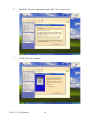
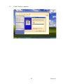
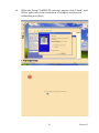
1
POC-155
Point-of-Care Terminal with 15"
TFT LCD
User Manual
Copyright
This document is copyrighted, © 2006. All rights are reserved. The original manufacturer reserves the right to make improvements to the products
described in this manual at any time without notice.
No part of this manual may be reproduced, copied, translated or transmitted in any form or by any means without the prior written permission of
the original manufacturer. Information provided in this manual is
intended to be accurate and reliable. However, the original manufacturer
assumes no responsibility for its use, nor for any infringements upon the
rights of third parties that may result from such use.
Acknowledgements
Award is a trademark of Award Software International, Inc.
VIA is a trademark of VIA Technologies, Inc.
IBM, PC/AT, PS/2 and VGA are trademarks of International Business
Machines Corporation.
Intel and Pentium are trademarks of Intel Corporation.
Microsoft Windows is a registered trademark of Microsoft Corp.
RTL is a trademark of Realtek Semiconductor Co., Ltd.
ESS is a trademark of ESS Technology, Inc.
UMC is a trademark of United Microelectronics Corporation.
SMI is a trademark of Silicon Motion, Inc.
Creative is a trademark of Creative Technology LTD.
All other product names or trademarks are properties of their respective
owners.
This manual is for the POC-175.
Part No. 2006015500
1st Edition, Printed in Taiwan Sep 2006
POC-155 User Manual
ii
FCC Class B
This equipment has been tested and found to comply with the limits for a
Class B digital device, pursuant to Part 15 of the FCC Rules.
These limits are designed to provide reasonable protection against harmful interference when the equipment is operated in a residential environment. This equipment generates, uses and can radiate radio frequency
energy. If not installed and used in accordance with this user manual, it
may cause harmful interference to radio communications.
Note that even when this equipment is installed and used in accordance
with this user manual, there is still no guarantee that interference will not
occur. If this equipment is believed to be causing harmful interference to
radio or television reception, this can be determined by turning the equipment on and off. If interference is occurring, the user is encouraged to try
to correct the interference by one or more of the following measures:
• Reorient or relocate the receiving antenna
• Increase the separation between the equipment and the receiver
• Connect the equipment to a power outlet on a circuit different from that
to which the receiver is connected
• Consult the dealer or an experienced radio/TV technician for help
Warning
Any changes or modifications made to the equipment
which are not expressly approved by the relevant
standards authority could void your authority to operate the equipment.
Caution
Danger of explosion if battery is incorrectly replaced.
Replace only with the same or equivalent type recommended by the manufacturer. Dispose of used
batteries according to the manufacturer’s instructions.
iii
Packing List
Before installing your Point of Care Terminal, ensure that the following
materials have been received:
• POC-155 series Point of Care Terminal
• User manual
• Accessories for POC-155
–
Y-shaped adapter for PS/2 mouse and keyboard
–
Power cord (1.8 m) - USA type (UK, German types are available
on request)
–
“Drivers and Utilities” CD-ROM disc
–
Mounting kits and packet of screws
Warning
To prevent electric shock, Do not remove cover.
No user serviceable parts inside, refer servicing to
qualified personnel.
Additional Information and Assistance
1.
Visit the Advantech websites at www.advantech.com or
www.advantech.com.tw where you can find the latest information
about the product.
2.
Contact your distributor, sales representative, or Advantech's customer service center for technical support if you need additional
assistance. Please have the following information ready before you
call:
a
Product name and serial number
b
Description of your peripheral attachments
c
Description of your software (operating system, version, application software, etc.)
d
A complete description of the problem
e
The exact wording of any error messages
POC-155 User Manual
iv
This equipment is a source of electromagnetic waves. Before use please,
make sure that there are not EMI sensitive devices in nearby which may
malfunction therefore.
Warning
1. Input voltage rated 100-240 VAC, 50-60 Hz, 4-2 A
(AC Mode)
2. Use a 3 V @ 195 mA lithium battery (Model No.
BR2032)
3. Packing: please carry the unit with both hands,
handle with care
4. Our European representative:
Advantech Europe GmbH
Kolberger Straße 7
D-40599 Düsseldorf, Germany
Tel: 49-211-97477350
Fax: 49-211-97477300
5. Maintenance: to properly maintain and clean the
surfaces, use only approved products or clean with a
dry applicator
Safety Instructions
1.
Read these safety instructions carefully.
2.
Keep this User Manual for later reference.
3.
Disconnect this equipment from any AC outlet before cleaning.
Use a damp cloth. Do not use liquid or spray detergents for cleaning.
4.
For plug-in equipment, the power outlet socket must be located
near the equipment and must be easily accessible.
5.
Keep this equipment away from humidity.
6.
Put this equipment on a reliable surface during installation. Dropping it or letting it fall may cause damage.
v
7.
The openings on the enclosure are for air convection. Protect the
equipment from overheating. DO NOT COVER THE OPENINGS.
8.
Make sure the voltage of the power source is correct before connecting the equipment to the power outlet.
9.
Position the power cord so that people cannot step on it. Do not
place anything over the power cord.
10.
All cautions and warnings on the equipment should be noted.
11.
If the equipment is not used for a long time, disconnect it from the
power source to avoid damage by transient overvoltage.
12.
Never pour any liquid into an opening. This may cause fire or electrical shock.
13.
Never open the equipment. For safety reasons, the equipment
should be opened only by qualified service personnel.
14.
If one of the following situations arises, get the equipment checked
by service personnel:
a
The power cord or plug is damaged.
b
Liquid has penetrated into the equipment.
c
The equipment has been exposed to moisture.
d
The equipment does not work well, or you cannot get it to work
according to the user manual.
e
The equipment has been dropped and damaged.
f
The equipment has obvious signs of breakage.
15.
DO NOT LEAVE THIS EQUIPMENT IN AN UNCONTROLLED
ENVIRONMENT WHERE THE STORAGE TEMPERATURE IS
BELOW -20° C (-4° F) OR ABOVE 60° C (140° F). THIS MAY
DAMAGE THE EQUIPMENT.
16.
If your computer is losing time or the BIOS configuration resets to
defaults, the battery has no power.
POC-155 User Manual
vi
Caution
1. Do not replace the battery yourself. Please contact
a qualified technician or your retailer.
2.The computer is provided with a battery-powered
real-time clock circuit. There is a danger of explosion
if the battery is incorrectly replaced. Replace only
with same or equivalent type recommended by the
manufacturer. Discard used batteries according to
the manufacturer’s instructions.
17.
IMPROPER VESA MOUNTING CAN RESULT IN SERIOUS
PERSONAL INJURY! VESA mount installation should be carried
out by a professional technician. Please contact the service technician or your retailer if you need this service.
18.
CLASSIFICATION:
Supply Class I adapter
No applied part
IPX1
Continuous Operation
Not AP or APG category
19.
Disconnect device: Appliance inlet.
20.
Follow national requirements when disposing of the unit.
21.
Maintenance: to properly maintain and clean the surfaces, use only
the approved products or clean with a dry applicator.
22.
Contact information:
No.1, Alley 20, Lane 26, Reuiguang Road Neihu District, Taipei,
Taiwan 114, R.O.C.
TEL: (02)27927818
23.
24.
This equipment must not be used for life support systems.
vii
25.
Accessory equipment connected to the analog and digital interfaces
must be in compliance with the respective nationally harmonized
IEC standards (i.e. IEC 60950 for data processing equipment, IEC
60065 for video equipment, IEC 61010-1 for laboratory equipment,
and IEC 60601-1 for medical equipment). Furthermore all configurations shall comply with the system standard IEC 60601-1-1.
Everybody who connects additional equipment to the signal input
part or signal output part configures a medical system, and is therefore, responsible that the system complies with the requirements of
the system standard IEC 60601-1-1. The unit is for exclusive interconnection with IEC 60601-1 certified equipment in the patient
environment and IEC 60XXX certified equipment outside of the
patient environment. If in doubt, consult the technical services
department or your local representative.
26.
Users must not to contact SIP/SOPs and the patient at the same
time.
27.
The sound pressure level at the operator's position according to IEC
704-1:1982 is no more than 70dB (A).
DISCLAIMER
POC-155 User Manual
This set of instructions is given according to
IEC 704-1. Advantech disclaims all responsibility for the accuracy of any statements contained
herein
viii
Contents
Chapter
Chapter
1 General Information ....................................... 2
1.1
1.2
Introduction ....................................................................... 2
Specifications .................................................................... 2
1.3
1.4
1.5
Cleaning/Disinfecting........................................................ 5
LCD Specifications ........................................................... 6
Dimensions........................................................................ 7
2.3
2.4
2.5
3.2
3.3
Chapter
A Quick Tour of the POC-155 ........................................ 10
Installation Procedures .................................................... 13
2.2.1
2.2.2
2.2.3
Connecting the power cord ......................................... 13
Connecting the keyboard and mouse ........................... 14
Switching on the power ............................................... 14
Running the BIOS Setup Program .................................. 15
Installing System Software.............................................. 15
Installing the Drivers....................................................... 16
3 Graphic Chipset Setup.................................. 20
3.1
Chapter
General ........................................................................... 2
Standard PC functions ................................................... 2
Flat panel interface ......................................................... 3
Audio function ............................................................... 3
Ethernet interface ........................................................... 4
Optional modules ........................................................... 4
Touchscreen (optional) .................................................. 4
Environment ................................................................... 5
2 System Setup.................................................. 10
2.1
2.2
Chapter
1.2.1
1.2.2
1.2.3
1.2.4
1.2.5
1.2.6
1.2.7
1.2.8
Introduction ..................................................................... 20
3.1.1
3.1.2
3.1.3
3.1.4
Chipset ......................................................................... 20
Display memory ........................................................... 20
LVDS Transmitter ...................................................... 20
Display types ................................................................ 20
Installation of Graphic Driver ......................................... 21
3.2.1
Installation for Windows XP ....................................... 22
Further information ......................................................... 28
4 Audio Interface.............................................. 30
4.1
4.2
Introduction ..................................................................... 30
Installation of Audio Driver ............................................ 30
4.3
Further information ......................................................... 32
4.2.1
Installation for Windows 2000/XP .............................. 31
5 Touchscreen Interface .................................. 34
5.1
Introduction ..................................................................... 34
5.1.1
5.1.2
5.1.3
General Information ..................................................... 34
General specifications .................................................. 34
Environmental specifications ....................................... 34
ix
5.2
5.3
Chapter
Installation of Touchscreen Drivers ................................ 35
5.2.1
Installation for Windows XP ....................................... 35
Further information ......................................................... 42
6 PCI Express Ethernet Interface................... 44
6.1
6.2
Introduction ..................................................................... 44
Installation of Ethernet Driver......................................... 44
6.3
Further information ........................................................ 46
6.2.1
Installation for Windows XP ....................................... 44
Appendix A Connector Pinouts ......................................... 48
A.1
A.2
A.3
A.4
A.5
A.6
A.7
A.8
A.9
A.10
A.11
A.12
A.13
ATX Power Connector.................................................... 48
Inverter Power Connector ............................................... 49
Internal Speaker Connector............................................. 50
Front Panel Control Connector (*Reserved)................... 50
IR Connector (*Reserved)............................................... 51
EIDE Hard Disk Drive Connector (Primary/Master)...... 52
CD-ROM Connector (Primary/Slave)............................ 54
CPU Fan Power Connector ............................................ 55
System Fan Power Connector ........................................ 56
PCI Bus Expansion Connector (PCI1) ............................ 56
CPU Selection Switches.................................................. 57
COM2.............................................................................. 58
Locating Connectors ....................................................... 59
Appendix B Jumper Setting and Connectors .................. 62
B.1
B.2
B.3
B.4
Jumpers and connectors .................................................. 62
B.1.1
B.1.2
B.1.3
Setting jumpers ............................................................ 62
Jumpers and switches ................................................... 62
Locating jumpers ......................................................... 63
CPU Configuration.......................................................... 64
COM port Interface ......................................................... 64
B.3.1
B.3.2
COM2 Output Type Setting (JP9) ............................... 65
COM1/COM2/COM3 Pin9 Output Type Setting (JP4/
JP6/JP5) 67
Watchdog Timer Configuration ...................................... 68
Appendix C Hardware Installation................................... 70
C.1
C.2
C.3
C.4
Overview of Hardware Installation and Upgrading ........ 70
Disassembling the Panel PC............................................ 71
Installing the 2.5" Hard Disk Drive (HDD) .................... 72
Installing the Central Processing Unit (CPU) ................. 73
Appendix D Programing the Watchdog Timer................ 76
Appendix E VESA Mounting ............................................ 80
E.1
Install VESA Mounting................................................... 80
POC-155 User Manual
x
CHAPTER
1
General Information
This chapter gives an overview of the
POC-155.
Sections include:
• Introduction
• Specifications
• Cleaning/Disinfecting
• LCD Specifications
• Dimensions
Chapter 1 General Information
1.1 Introduction
The POC-155 is a multimedia Pentium® Mobile processor-based computer that is designed to serve as a Point of Care terminal (POC). It is a
PC-based system with 15" color TFT LCD display, on-board PCI express
Ethernet controller, multiple COM port interfaces and 18-bit stereo audio
controller. With a built-in CD-ROM drive and mini PCI expansion slot,
the POC-155 is as compact and user-friendly as a notebook computer.
This simple, complete and highly integrated multimedia system lets system integrators easily build a Point of Care Terminal into their applications. Common industrial applications include factory automation
systems, precision machinery, and production process control. It is also
suitable for many non-industrial applications, including interactive kiosk
systems, entertainment management, and car park automation. The POC155 is a reliable, cost-effective solution to your application's processing
requirements.
1.2 Specifications
1.2.1 General
• Dimensions (W x H x D): 414 x 339 x 115 mm (16.30" x 13.34" x
4.52")
• Weight: 6.5 kg (14.4 lb)
• Power supply:
–
AC model: (180 watts)
–
Input voltage 100 ~ 240 VAC, 4/2 A max. @ 50 ~ 60 Hz
–
Output voltages +5 V @ 12 A, +12 V @ 12 A, +3.3 V @ 16.8 A,
+5 Vsb @ 2.0 A, -12V @ 0.8 A
• Cooling fan dimensions (L x W x H): 60 x 60 x 10 mm (2.4" x 2.4" x
0.4")
• Disk drive housing: Space for one 2.5" HDD, one 12.7 mm Compact
CD-ROM drive.
• Front panel: IP65/NEMA compliant
• Whole System: IPX1 compliant
1.2.2 Standard PC functions
POC-155 User Manual
2
• CPU: Socket 479 Intel® Pentium® Mobile up to 2.0 GHz
• BIOS: Award 512 KB Flash BIOS, supports Plug & Play, APM
• Chipset: Intel® 915GM GMCH, 82801FBM (ICH6-M)
• Front side Bus: FSB 533/400 MHz
• RAM: 240 pins DDR2 DIMM slots x 2, supports unbuffered 400/533
MHz DDR2 SDRAM (Non ECC), capacity maximum to 2 GB
• IDE interface: ATA/100 x 1. Supports one IDE device.
• SATA interface: SATA x 1. Supports one SATA device.
• Parallel port: Parallel port x 1, supports SPP/BPP/EPP/ECP parallel
mode.
• Serial ports: RS-232 port x 3, they are all compatible with 16C550
UARTs. COM2 has optical isolation and supports RS-422/485 by
jumper selection; COM1/COM2/COM3 support +5 by jumper
selection
• Universal serial bus (USB) port: USB 2.0 port x 8 (6 external, 2
internal)
• IEEE 1394 port: IEEE 1394a port x 3.
• Expansion slot: PCI 33 MHz slot x 1
• Watchdog timer: 62-level, interval 1 ~ 62 seconds. Automatically
generates system reset when the system stops due to a program error or
EMI.
• CMOS Battery (BIOS): 3.0 V @ 195 mA lithium battery
1.2.3 Flat panel interface
• SDVO Interface: Chrontel 7308A Single/Dual LVDS transmitter
• Display resolution: Supports LVDS LCD panel resolutions up to 1600
x 900
• Graphic Chipset: Intel® Graphics Media Accelerator (GMA) 900
• Shared memory: Dynamic Video Memory Technology (DVMT) 3.0
to dynamically allocate up to 128 MB of system memory for graphics
usage.
• Display type: Simultaneously supports CRT
1.2.4 Audio function
• Chipset: Realtek ALC203, compliant with AC’97 rev 2.2
• Audio controller: 18-bit codec, full-duplex stereo codec
3
Chapter 1
• Audio interface: Microphone-in, Line-in, Line-out
• Internal Speaker: 1 W speaker x 2, Full alarm volume > 70 dB(A) 1
meter
1.2.5 Ethernet interface
• Chipset: Marvell 88E8053 PCI express high performance Gigabit
Ethernet controller
• Ethernet interface: Gigabit Ethernet port x 2. Fully integrated Gigabit
Ethernet Media Access Control (MAC) and Physical Layer (PHY)
functions, each providing a standard IEEE 803.3 Ethernet interface for
1000BASE-T, 100BASE-TX and 10BASE-T applications.
1.2.6 Optional modules
• CPU: Intel® Pentium® M 1.6 GHz, 1.8 GHz, 2.0 GHz
• Memory: 256 MB / 512 MB / 1 GB, DDR2 400/533 MHz SDRAM
• HDD: 2.5", 40 GB / 60 GB / 80 GB, 4200rpm, PATA HDD or 40 GB /
80 GB, 5400 rpm, SATA HDD
• Touchscreen: Analog resistive
• CD-ROM drive: Compact 24X CD-ROM or above
• COMBO drive: Compact 8X DVD-ROM, 24X CD-ROM, 24X CDR, 24X CD-RW
• DVD-RW drive: Compact 8X DVD-ROM, 24X CD-ROM, 24X CDR, 10X CD-RW, 4X DVD-RW
• Mini PCI WLAN module: 802.11b/g WLAN
1.2.7 Touchscreen (optional)
Type
Resolution
Light Transmission
Controller
Power Consumption
Software Driver
Durability (touches in a lifetime)
Analog Resistive
Continuous
75%
RS-232 interface (uses COM4)
+5 V @ 200 mA
Supports Windows 2000,Windows XP
30 million
Table 1.1:Touchscreen specification
POC-155 User Manual
4
Note
The Point of Care Terminal with the optionally
installed touchscreen will share COM4. Once the
touchscreen is installed, COM4 cannot be used for
other purposes.
1.2.8 Environment
• Temperature: 0 ~ 40° C (32 ~ 104° F)
• Relative humidity:
–
20% ~ 90% RH at 10 ~ 40° C operating
–
10% ~ 95% RH at -20 ~ 50 °C Storage (Non-condensing)
• Shock: 30G, half sine, 11 msec duration
• Vibration Sinusoidual Test: 5 ~ 500 Hz, 1G acceleration, non-operating
• Power MTBF: 100,000 hrs
• Altitudes: Operating: 6,000 feet; Shipping: 40,000 feet
• Certifications:
–
EMC: CE, FCC approved
–
Safety: UL60601-1 and EN60601-1 approved.
–
This device bears the CE label in accordance with the provisions of
the EMC Directive 89/336/EMC.
1.3 Cleaning/Disinfecting
During normal use of the POC-155 may become soiled and should, therefore, be cleaned regularly. Agents: Green tinctured soap and Enzymatic
detergents.
Steps:
1.
Wipe the POC-155 with a clean cloth that has been moistened in
the cleaning solution.
2.
Prepare agent as per the manufacturer’s instructions or hospital
protocol.
3.
Wipe the POC-155 thoroughly with a clean cloth
5
Chapter 1
Cautions
Do not immerse or rinse the POC-155 and its peripherals. If you accidentally spill liquid on the device, disconnect the unit from the power source. Contact your
Biomed regarding the continued safety of the unit
before placing it back in operation.
Do not spray cleaning agent on the chassis.
Do not use disinfectants that contain phenol.
Do not autoclave or clean the POC-155 or its peripherals with strong aromatic, chlorinated, ketone, ether,
or Esther solvents, sharp tools or abrasives. Never
immerse electrical connectors in water or other liquids.
1.4 LCD Specifications
• Display type: 15" TFT LCD.
• Resolution: 1024 x 768
• Colors: 262,144 (6 bits/color)
• Dot size (mm): 0.264 x 0.264
• Viewing angle: 120°
• Luminance: 350 cd/m2
• Contrast ratio: 400:1
• LCD MTBF: 50,000 hours
• Backlight lifetime: 50,000 hours @ Standard current 6.5 ±0.5 mA
POC-155 User Manual
6
115
1.5 Dimensions
342
416
Figure 1.1: Dimensions of the POC-155
7
Chapter 1
POC-155 User Manual
8
CHAPTER
2
System Setup
This chapter gives hardware and system software installation information.
Sections include:
• A Quick Tour of the POC-155
• Installation Procedures
• Running the BIOS Setup Program
• Installing System Software
• Installing the Drivers
Chapter 2 System Setup
2.1 A Quick Tour of the POC-155
Before you start to set up the POC-155, take a moment to become familiar with the locations and purposes of the controls, drives, connections
and ports, which are illustrated in the figures below.
When you place the POC-155 upright on the desktop, its front panel
appears as shown in Figure 2-1.
Volume adjustment
Brightness adjustment
Power Indicator LED (Green- Power ON)
Figure 2.1: Front View of the Point of Care Terminal
POC-155 User Manual
10
When you look at the left side of the panel PC, you will see the CD-ROM
drive, two USB 2.0 ports and two IEEE1394a ports, as shown in Figure 22.
IEEE 1394a
USB 2.0
Figure 2.2: Left side view of the Point of Care Terminal
When you turn the Point of Care Terminal around and look at its rear
cover, you will find the PCI expansion slot located on the left side. This
slot is covered by a side panel cover. The sunken I/O section is at the bottom of the panel PC, as shown in Figure 2-3. (The I/O section includes
11
Chapter 2
various I/O ports, including serial ports, parallel port, Ethernet ports,
USB ports, the microphone jack, and so on).
1
2
3
4
5
6
7
8
9
Figure 2.3:
1
2
3
4
5
6
7
8
9
Functional Earth Ground Connector
Isolated RS-232 COM port (COM1 /COM2/COM3)
PS/2 Mouse/Keyboard Port
IEEE-1394a Port
Parallel Port
Line-out/Line-in/MIC-in Port (From left to right)
D-sub VGA port
USB 2.0 Ports
RJ-45 Gigabit LAN Port
POC-155 User Manual
12
2.2 Installation Procedures
2.2.1 Connecting the power cord
Be sure to always handle the power cords by holding the plug ends only.
1.
Connect the female end of the power cord to the AC inlet of the
panel PC. (See Figure 2-5.)
2.
Connect the 3-pin male plug of the power cord to an electrical outlet.
Figure 2.4: Connecting the power cord
13
Chapter 2
2.2.2 Connecting the keyboard and mouse
1.
Connect the Y-shaped adapter to the PS/2 mouse and keyboard port
on the I/O section of the POC-155. (See Figure 2-6.)
2.
Connect the PS/2 mouse and keyboard to the Y-shaped adapter.
If you use a serial mouse, you can connect the mouse to any COM port in
the I/O section.
Figure 2.5: Connecting the mouse and keyboard
2.2.3 Switching on the power
Switch on the power switch on the rear cover.
POC-155 User Manual
14
2.3 Running the BIOS Setup Program
Your POC-155 is likely to have been properly set up and configured by
your dealer prior to delivery. You may still find it necessary to use the
BIOS (Basic Input-Output System) setup program to change system configuration information, such as the current date and time or your type of
hard drive. The setup program is stored in read-only memory. It can be
accessed either when you turn on or reset the panel PC, by pressing the
“Crtl+Alt+Del.” keys on your keyboard immediately after powering on
the computer.
The settings you specify with the setup program are recorded in a special
area of memory called CMOS RAM. This memory is backed up by a battery so that it will not be erased when you turn off or reset the system.
Whenever you turn on the power, the system reads the settings stored in
CMOS RAM and compares them to the equipment check conducted during the power on self-test (POST). If an error occurs, an error message
will be displayed on screen, and you will be prompted to run the setup
program.
2.4 Installing System Software
Recent releases of operating systems from major vendors include setup
programs which load automatically and guide you through hard disk
preparation and operating system installation. The guidelines below will
help you determine the steps necessary to install your operating system
on the panel PC hard drive.
Note
Some distributors and system integrators may have
already pre-installed system software prior to shipment of your panel PC.
If required, insert your operating system's installation or setup diskette
into the optical drive until the release button pops out. (See Figure 2-14)
The BIOS supports system boot-up directly from the CD-ROM drive.
You may also insert your system installation CD-ROM disk into the CDROM drive.
15
Chapter 2
Power on or reset the system by pressing the “Ctrl+Alt+Del” keys simultaneously. The Point of Care Terminal will automatically load the operating system from the diskette or CD-ROM.
If you are presented with the opening screen of a setup or installation program, follow the instructions on screen. The setup program will guide
you through preparation of your hard drive, and installation of the operating system.
Busy indicator
Eject button
Emergency eject hole
Figure 2.6: Insert the disk to CD-ROM drive
2.5 Installing the Drivers
After installing your system software, you will be able to set up the Ethernet, SVGA, audio and touchscreen functions. All the drivers except the
CD-ROM drive driver are stored in a CD-ROM disc entitled “Drivers and
Utilities which can be found in your accessory box.
The standard procedures for installing the SVGA, audio, touchscreen, and
Ethernet drivers are described in Chapters 3, 4, 5, and 6 respectively.
The utility directory includes multimedia programs. Refer to the
README.TXT file inside the VGA folders for more detailed information.
POC-155 User Manual
16
The various drivers and utilities in the CD-ROM disc have their own text
files which help users install the drivers and understand their functions.
These files are a very useful supplement to the information in this manual.
For your reference, the directory of drivers on the “Drivers and Utilities”
CD-ROM is:
Figure 2.7: The file directory on “Drivers and Utilities” CD-ROM
Note
The drivers and utilities used for the POC-155 panel
PCs are subject to change without notice. If in doubt,
check Advantech's website or contact our application
engineers for the latest information regarding drivers
and utilities.
17
Chapter 2
POC-155 User Manual
18
CHAPTER
3
Graphic Chipset Setup
This chapter gives details of graphics
chipset setup.
Sections include:
• Introduction
• Installation of Graphic Driver
• Further information
Chapter 3 Graphic Chipset Setup
3.1 Introduction
The POC-155 has an onboard VGA interface. The specifications and features are described as follows:
3.1.1 Chipset
The POC-155 uses Mobile Intel® 915GM Express chipset for its graphic
controller. It supports SDVO device, and CRT monitors. The Mobile
Intel® 915GM Express chipset is a component of the Intel® Centrino®
mobile technology. Featuring the Intel® Graphics Media Accelerator
900, the 915GM chipset enables twice the graphics performance of the
previous generation of platforms based on the Intel® 855GME chipset.
3.1.2 Display memory
Maximum memory allocation is based on the total system memory. 1 MB
or 8 MB of pre-allocated memory is supported.
3.1.3 LVDS Transmitter
The POC-155 uses Chrontel CH7308A for driving its LCD panel. The
CH7308A is a display controller device, which accepts digital graphics
input signals, upscales, encodes, and transmits data through an LVDS
transmitter to an LCD panel. The CH7308A operates at pixel rates of up
to 140 MHz, and support 18/24-bit LCD panels.
3.1.4 Display types
CRT and panel displays can be used simultaneously. The POC-155 can
be set in one of three configurations: CRT only, LVDS only, both CRT
and LFP (LVDS). The system is initially set to simultaneous display
mode—CRT and LFP (BIOS default setting).
The analog CRT DAC interface supports maximum DAC frequency up to
400 MHz, 24-bit RAMDAC, DDC2B compliant, and resolution up to
2048 x 1536.
POC-155 User Manual
20
3.2 Installation of Graphic Driver
Complete the following steps to install the SVGA driver. Follow the procedures in the flow chart that apply to the operating system that you are
using within your POC-155.
Important
The following windows illustrations are examples
only. You must follow the flow chart instructions and
pay attention to the instructions which appear on your
screen.
Note1
The CD-ROM drive is designated as “D” throughout
this chapter.
Note2
<Enter> means pressing the “Enter” key on the keyboard.
Note3
Before you install the graphic driver of POC-155,
please ensure you have installed the “Intel Chipset
Software Installation Utility”. You can find this driver
in the Utility CD-ROM.
Note4
The resolution of window display will be fixed at 640 x
480 before you install VGA driver. Depend on your
LCD native resolution, the black area might be different.
21
Chapter 3
3.2.1 Installation for Windows XP
1.
Click the 'Start' button in the task bar, click 'Run' and then select
'infinst_autol.exe' from the drive directory “D:/Chipsetsoftware/”
where the driver files are stored. The Install dialog will appear.
2.
Click 'Next' to continue.
POC-155 User Manual
22
3.
Read the License Agreement and click ‘Yes’ to proceed.
23
Chapter 3
4.
When the 'Setup COMPLETE' message appears click 'Finish' to
restart your computer.
POC-155 User Manual
24
1.
Click the 'Start' button in the task bar, click 'Run' and then select
‘Setup.exe’ from the drive directory “D:/VGA/” where the driver
files are stored. The Install dialog will appear.
2.
Click 'Next' to continue.
25
Chapter 3
3.
Read the License Agreement and click ‘Yes’ to proceed.
POC-155 User Manual
26
4.
When the 'Setup COMPLETE' message appears click 'Finish' to
restart your computer.
27
Chapter 3
3.3 Further information
For further information about the VGA installation in your POC-155,
included driver updates, troubleshooting guides and FAQ lists please visit
the following web resources.
Intel website:
www.intel.com.tw
Advantech websites:
www.advantech.com
www.advantech.com.tw
POC-155 User Manual
28
CHAPTER
4
Audio Interface
This chapter gives details of audio
interface setup.
Sections include:
• Introduction
• Installation of Audio Driver
• Further information
Chapter 4 Audio Interface
4.1 Introduction
The POC-155's onboard audio interface provides high-quality stereo
sound and FM music synthesis (ESFM) by using the ALC202 audio controller from Realtek. The audio interface can record, compress, and play
back voice, sound, and music with a built-in mixer control. The POC155's onboard audio interface also supports the Plug and Play (PnP) standard and provides PnP configuration for audio, FM, and MPU-104 logical devices. It is compatible with Sound Blaster, Sound Blaster Pro
version 3.01, voice, and music functions. The ESFM synthesizer is register compatible with the OPL3 and has extended capabilities.
4.2 Installation of Audio Driver
Before installing the audio driver, please take note of the procedures
detailed below. You must know which operating system you are using in
your POC-155, and then refer to the corresponding installation flow
chart. Just follow the steps in the flow chart. You can quickly and successfully complete the installation, even though you are not familiar with
instructions for Windows.
Important
The following windows illustrations are examples
only. You must follow the flow chart instructions and
pay attention to the instructions which appear on your
screen.
Note1
The CD-ROM drive is designated as “D” throughout
this chapter.
Note2
<Enter> means pressing the “Enter” key on the keyboard.
POC-155 User Manual
30
4.2.1 Installation for Windows 2000/XP
1.
Click the 'Start' button in the task bar, click 'Run' and then select
'infinst_autol.exe' from the drive directory “D:/Audio/” where the
driver files are stored. The Install dialog will appear.
2.
Click 'Next' to continue.
31
Chapter 4
3.
Click 'Next' to continue.
4.
When the 'Setup COMPLETE' message appears click 'Finish' to
restart your computer.
4.3 Further information
For further information about the audio interface installation in your
POC-155, included driver updates, troubleshooting guides and FAQ lists
please visit the following web resources.
Realtek website:
www.realtek.com.tw
Advantech websites:
www.advantech.com
www.advantech.com.tw
POC-155 User Manual
32
CHAPTER
5
Touchscreen Interface
This chapter gives details of touchscreen interface setup.
Sections include:
• Introduction
• Installation of Touchscreen Drivers
• Further information
Chapter 5 Touchscreen Interface
5.1 Introduction
5.1.1 General Information
The POC-155's optional touchscreen incorporates advanced second-generation 5-wire resistive technology. They allow 75% light transmission.
The resistive and capacitive models have an antiglare surface. All models
provide greatly enhanced visual resolution. They also have new improved
scratch-resistant features.
The touchscreen is manufactured from UL-recognized components.
When properly installed, the touchscreen's ball impact resistance meets
the UL 1950 standard. Its fire resistance meets the UL-746C, 19 mm
(0.75") flame test standard. Systems incorporating the touchscreen, controllers, and cables have been approved to FCC Class A and Class B standards.
5.1.2 General specifications
Please refer to Chapter 1, Section 1.2 of this manual.
5.1.3 Environmental specifications
• Temperature:
–
-0 ~ 40° C (operating)
–
-20 ~ 60° C (storage)
• Relative humidity:
–
90 RH at 35° C (operating)
–
90 RH at 35° C for 240 hours, non-condensing (storage)
• Chemical resistance: The active area of the touchscreen is resistant to
the following chemicals when exposed for a period of one hour at a
temperature of 21° C (71° F):
–
Acetone
–
Methylene chloride
–
Methyl ethyl ketone
–
Isopropyl alcohol
–
Hexane
–
Ammonia-based glass cleaners
–
Turpentine
POC-155 User Manual
34
–
Mineral spirits
–
Foods and beverages
5.2 Installation of Touchscreen Drivers
To facilitate installation of the touchscreen driver, you should read the
instructions in this section carefully before you attempt installation.
Important
The following windows illustrations are examples
only. You must follow the flow chart instructions and
pay attention to the instructions which appear on your
screen.
Note1
The CD-ROM drive is designated as “D” throughout
this chapter.
Note2
<Enter> means pressing the “Enter” key on the keyboard.
5.2.1 Installation for Windows XP
1.
Click the 'Start' button in the task bar, click 'Run' and then select
'sw500930.exe' from the drive directory “D:/Elotouch/” where the
driver files are stored. The Install dialog will appear.
35
Chapter 5
2.
Click 'Ok' to continue.
3.
Click 'Unzip' to continue.
POC-155 User Manual
36
4.
Click 'Ok' to continue.
5.
Click 'Next' to continue.
37
Chapter 5
6.
Read the License Agreement and click ‘Yes’ to proceed.
7.
Click 'Next' to continue.
POC-155 User Manual
38
8.
Click 'Next' to continue.
39
Chapter 5
9.
Click 'Next' to continue.
POC-155 User Manual
40
10.
When the 'Setup COMPLETE' message appears click 'Finish'. And
follow upthe on-screen instructions to complete touchscreen
calibration procedures.
41
Chapter 5
5.3 Further information
For further information about the Touchscreen installation in your POC155, included driver updates, troubleshooting guides and FAQ lists please
visit the following web resources.
Elo website:
www.elotouch.com
Advantech websites:
www.advantech.com
www.advantech.com.tw
POC-155 User Manual
42
CHAPTER
6
PCI Express Ethernet
Interface
This chapter gives details of Ethernet
interface setup.
Sections include:
• Introduction
• Installation of Ethernet Driver
• Further information
Chapter 6 PCI Express Ethernet Interface
6.1 Introduction
The POC-155 is equipped with a high performance Marvell 88E805 PCIe
Ethernet chipset 3 which is fully compliant with IEEE 802.3 10/100/1000
Mbps standards. The Ethernet port provides a standard RJ-45 jack.
6.2 Installation of Ethernet Driver
6.2.1 Installation for Windows XP
1.
Click the 'Start' button in the task bar, click 'Run' and then select
'SetupYukonWin.exe' from the drive directory “D:/LAN_Marvell/”
where the driver files are stored. The Install dialog will appear.
2.
Click 'Next' to continue.
POC-155 User Manual
44
3.
Click 'Next' to continue.
4.
When the 'Setup COMPLETE' message appears click 'Finish' to
restart your computer.
45
Chapter 6
6.3 Further information
For further information about the Ethernet installation in your POC-155,
included driver updates, troubleshooting guides and FAQ lists please visit
the following web resources.
Marvell website:
www.marvell.com
Advantech websites:
www.advantech.com
www.advantech.com.tw
POC-155 User Manual
46
APPENDIX
A
Connector Pinouts
This appendix gives details of connector pinouts.
Sections include:
• ATX Power Connector
• Inverter Power Connector
• Internal Speaker Connector
• Front Panel Control Connector
(*Reserved)
• IR Connector (*Reserved)
• EIDE Hard Disk Drive Connector(Secondary Master)
• CD-ROM Connector (Primary Master)
• CPU Fan Power Connector
• System Fan Power Connector
• PCI Bus Expansion Connector
(PCI1)
• CPU Selection Switches
• COM2
• Locating Connectors
Appendix A Connector Pinouts
A.1 ATX Power Connector
Figure A.1: POC-155 ATX power connector
Table A.1: ATX power connector (CN37)
Pin No.
1
2
3
4
5
6
7
8
9
10
11
12
13
14
Signal Description
3.3V
3.3V
GND
5V
GND
5V
GND
POK
5 VSB
12 V
3.3V
-12V
GND
PSON
POC-155 User Manual
48
15
16
17
18
19
20
GND
GND
GND
-5V
5V
5V
A.2 Inverter Power Connector
Figure A.2: POC-155 Inverter power connector
Table A.2: Inverter power connector (CN3
Pin No.
1
2
3
4
5
Signal Description
+12 V
GND
ENABLE
Brightness Adjustment
+5V
49
Appendix A
A.3 Internal Speaker Connector
Figure A.3:
Table A.3: POC-155 Internal speaker connector(CN26)
Pin No.
1
2
3
4
Signal Description
Speaker out_RSpeaker out_R+
Speaker out_L+
Speaker out_L-
A.4 Front Panel Control Connector (*Reserved)
Figure A.4: POC-155 Flat panel control connector
POC-155 User Manual
50
Table A.4: Power connector (J4)
Pin No.
1
2
Signal Description
Power SW+
Power SW-
Table A.5: Reset connector (J3)
Pin No.
1
2
Signal Description
RESET SW
GND
A.5 IR Connector (*Reserved)
Figure A.5: POC-155 IR connector
Table A.6: IR connector (CN12)
Pin No.
1
2
3
4
5
Signal Description
Vcc
NC
IR_IN
GND
IR_OUT
51
Appendix A
A.6 EIDE Hard Disk Drive Connector (Primary/Master)
Figure A.6: POC-155 EIDE hard drive connector
Table A.7: EIDE hard disk connector (CN10)
Pin No.
1
2
3
4
5
6
7
8
9
10
11
12
13
Signal Description
IDE RESET#
GND
DATA7
DATA8
DATA6
DATA9
DATA5
DATA10
DATA4
DATA11
DATA3
DATA12
DATA2
POC-155 User Manual
52
14
15
16
17
18
19
20
21
22
23
24
25
26
27
28
29
30
31
32
33
34
35
36
37
38
39
40
41
42
43
44
DATA13
DATA1
DATA14
DATA0
DATA15
SIGNAL GND
NC
HDD DREQ
GND
IO WRITE
GND
IO READ
GND
HD READY
CABLE SELECT
HD ACK0#
GND
IRQ14
NC
ADDR1
NC
ADDR0
ADDR2
HDD SELECT 0#
HDD SELECT 1#
IDE ACTIVE 0#
GND
Vcc
Vcc
GND
NC
# Low active
53
Appendix A
A.7 CD-ROM Connector (Primary/Slave)
Table A.8: CD-ROM connector (CN7)
Pin No.
1
2
3
4
5
6
7
8
9
10
11
12
13
14
15
16
17
18
19
20
21
22
23
24
25
26
27
28
29
30
31
32
33
Signal Description
Audio_L
Audio_R
GND
GND
IDE RESET #
DATA8
DATA7
DATA9
DATA6
DATA10
DATA5
DATA11
DATA4
DATA12
DATA3
DATA13
DATA2
DATA14
DATA1
DATA15
DATA0
HDD DREQ
GND
IO READ
IO WRITE
GND
HD READY
HD ACK0#
IRQ15
NC
ADDR1
NC
ADDR0
POC-155 User Manual
54
34
35
36
37
38
39
40
ADDR2
HDD SELECT 0#
HDD SELECT 1#
Vcc (+5V)
Vcc (+5V)
GND
GND
A.8 CPU Fan Power Connector
Figure A.7: POC-155 CPU fan connector
Table A.9: CPU fan power connector (CN19)
Pin No.
1
2
3
Signal Description
FAN_DET
+12V
GND
55
Appendix A
A.9 System Fan Power Connector
Figure A.8: POC-155 System fan connector
Table A.10: System fan power connector (CN39)
Pin No.
1
2
3
Signal Description
FAN_DET
+12V
GND
A.10 PCI Bus Expansion Connector (PCI1)
Figure A.9: POC-155 PCI slot connector
Note
This PCI slot uses standard PCI Bus V2.2. If you
wish to use this slot, you can connect the add-on
cards directly without any issues.
POC-155 User Manual
56
A.11 CPU Selection Switches
Table A.11: CPU Selection Switch SW1
Pin No.
1
2
3
4
5
6
Dothan
(Default)
OFF
ON
ON
OFF
OFF
ON
Banias 533
Banias 400
ON
OFF
ON
OFF
ON
OFF
ON
OFF
ON
OFF
ON
OFF
Table A.12: CPU Selection Switch SW2
Pin No.
1
2
3
4
Dothan
(Default)
OFF
ON
OFF
ON
57
Banias 533
Banias 400
ON
OFF
OFF
ON
OFF
OFF
ON
OFF
Appendix A
A.12 COM2
Figure A.10: POC-155 COM2 connector
Table A.13: COM2 pin assignment
Configure
Pin No.
1
2
3
4
5
6
7
8
9
POC-155 User Manual
Signal Description
RS-232
RS-422
DCD
TXRX
TX+
TX
RX+
DTR
RXGND
GND
DSR
-RTS
-CTS
-RI
--
58
RS-485
DATADATA+
--------
L68
CN27
R929
L67
L70
H13
CN28
59
U59
C571
L71
L18
L66
L65
L64
L63
U79
CN26
R234
C206
C207
J8
C631
U44
F2
CN29
CN31
R719
R727
C208
F9
C629
C634
F3
F4
R855
R849
C698
R854
C697
R856
F8
C731 L92 C716
C
TP43
R839 C345 C346
R377
Y2
R388
C370
C369
C368
C367
R430 M53
R405
R416
R415 RP4
RP2
R428
R555
Q34
R556
Q35
R558
Q44
U58
R840
C699
E
U92
C
M83
M82
CK5
U13
R890
CN34
L44
U84
Y3
R571
C487
R583
C494
R576
R575
R574
R572
CN9
CN8
CN42
C153
U62
U64
R448
R435
R440
R427
R431
R439
C87
R557
R554
R553
R551
R550
U99
U70
C701
E
C702
R859
R860 R858
C703 R857
C704 C734
F5
U65
J6
Y9
CN21
U63
C492
FS7
C826
C225
C832 C226
C831
C833
D21
LED2
R394
C119
C639
C403
C640
C344
R578
CN7
U66
C563
CN10
C785 R552
L98 R547
C786
C787 C479
C788 R548
L97 R549
C771
C372
C371
FB2
LED12
C402
C770
C810
R939
C811
R289
L21
R973
R888
R887
R886
C752
C784
C783
C835
U12
C578
R73
C220
C222
C223
R279
C221
CN3
LED10
RP6
U15
R395
C358
D22
LED11
B
R586
Q37
LED6 R584
R788
U85
L10
C123
R87
Q18
R96
L20
Q27
L19
L11
CN37
U42
R975
R974
M60
R141
CN24
R710
C93
C824
M48
BT1
M49
R398
R397
R396
M13
C359
D17
R97
R89
R93
C122
Q19
C109
R84
R85
R83
R82
R72
R71
R74
R75
R77
R76
C115
C809 FB1
Q46
U46
C348
C349
L87
C670
CN25
R378
R390
R383
R442
R417
R407
R408
R409
R406
R392
R391
C355
C354
C357
C356
C351
C350
C353
C352
R88
R90
R91
R92
R94
R95
C113
C114
R66
U22
C102
R937
C564
R688
C565
R262
TP8 R258
C92
U86
R790
C667
R793
R792
R799
R800
R794
C107
R65
R78
R64
R70
C110
C101
U25
D16
C819
C715
RP7
RP8
R424
A
R386
R381
R382
R389
C85
R798
R801
R795
R789
C661
R830
B
C755
R233
R235
U40
R721
R720
CN4
R853
R852
R851
C700
C729
C728
R722
C20
C726
C600 C599
L81
C648
A
Q47
C733
C732
R913
Q45
L30
C827
C584
C793
U77
R829
R170
R169
C100
H
C794
Y8
C252
C738
TP20
CN35
R270 C682
JP1
C739
L29
U83 R760
R759
C278
R804
R805
C668
R807
C662
L85
L77
C614
C613
C612
C611
C610
C609
C608
L82
C649
R287
C249
M85
TP21
U87
M84
C277
C248 C664
J4
CN36
H16
L86
R753
R754
H11
TP4
R161
R163
SW1
L78
JP5
R253
R251
C688
R154
R155
R755
R756
C302
C194
C259
C262
C681
C251
L34
C300
C95
C299
R201
R204
R194
R197
R189
R191
C94
C686
C261
C260
C687
R255
R260
R282
R256
R284
TP7
C376
C296
R228
R199
R196
J3
U39
C671
R809
R816
R821
R818
R826
C678
R824
R823
R166
R168
R162
TP2
R164
C255
U73
C443
R165
D15
C227
R832
L74
C630
L75
C632
SP1
R245
R247
H4
R288
Q28
CN23
CN22
FS2 R542 R541
R770
R767
R768
R766
R765
R772
R769
R305
C448
C188
C189
C224
R876
R877
R878
R879
R880
R881
R882
R883
R669
M41
R667
CN16
C680
R250
R249
R159
R158
M9
JP7
R252
C99
M87
R281
CN32
C440
C672
C215
U38
L23
L22
C340
C341
C152
H3
R303
R304
R301
R300
R299
R302
M11
U48
C342
R280
C683
C257
C19
C653
C652
C651
C654
C655
C658
C657
H19
L24
R309
L25
U47
C343
U41
R69
R737
R735
R734
R736
R738
C619
U89
C294
R203
R193
R178
R180
R174
R176
R215
R217
R763
R764
R186
R188
M62
C210
Q25
Q26
R815
R820
R232
R817
R177
R179
R825
R173
C677
R175
R810
R181
R183
R761
R762
R185
R187 Y1
C205 C204
C212
R226
R223
R222
R230
R229
R236
R218
R220
R214
R216
R210
R212
R828
R827
C303
R237
R182
R184
R219
R221
R211
R213
Y7 R202
R205
R195
R198
R190
R192
C297
C211
C213
C214
M75
M61
R79
R730
R486
M86
R725
M74
R726
C601
R724
R723
C301
U91
C298
U90
J5
JP3
R841
R842
R843
R844
R845
R846
R847
R848
R617
M40
R615
CN20
Inverter Power
CN6
CN14
C209
L90
M58
C284
C285
C286
L35
C437
R482
RP11 RP10
C295
C118
C621
M73
C603
C604
C605
C606
R740
R739
R483
R965
C575
L32
C258
C256
C684 L31
R254
C217
SW2
R749 C625
C627
R746
R748 C623
R750 R743
R751 R744
R752 C626
C628 R747
U50
C308
RN12
RN11
RN13
RN8
RN9
RN10
R782
R783
C309
C313
C674
M66
R713 R715
R712
R711
C434 M65
R470
R469
R464
R465
R466 R717
L88
R367
CN30
U56 FS4
R371
L52
U57
R494
R369
R372
CN17
CN15
L89
C436
R495
R487
R745
C622 C624
R741
R742 R928
Q33
R368
R238
R239
PCM-9690 REV.A1
19C6969002
MADE IN TAIWAN
C834
R467
R468
M67
JP8
M64
R510
R563
M63
R370
R525
C438
C116
R522
R492
C576
R507
L47
C304
RN6
RN5
RN4
RN2
RN1
RN3
R780
R781
C312
R513
CN18
R504
L49
D2IMM1
M37
R559
C439
J2
R485
R488
M18
D2IMM2
L48
M17
M19
C591
C590
S10
S13
S19
S4
U49
PCI1
U32
C142
R142
R140
R139
R137
LED4
C660
C659
C656
MC1
CN2
C781
FS3
R491
LED5
CN12
PCIE2-1X1
CN38
R135
C141
R133 R132
R131 R130
R129 R127
R524
J1
RTX1
CN13
R121
R123
R125
R120
R124
R126 U31
R509
R560
R561
R562
R471
R472
R134
R523
R500
R508
Power
Switch
R505
R506
Reset
Switch
JP6
S9
S8
S11
S17
S6
S18
S12
S3
IR
JP9
JP4
C117
R422
ATX Power
R787
R503
R502
R540
R511
R520
R497
R546
R544
R521
R545
R543
R512
A.13 Locating Connectors
CPU selection
LVDS2/ LVDS1
JP2
CN5
01-3
FB5
H5
C825
FB4
C817
CN43
H
R403
LED3
D23
C10
U60
JP10
JP11
C491
R379
U76
U88
S1
FS8
Q48
D20
U75
R709
R708
R707
R706
R703
R702
R701
R700
R695
R696
R691
R690
C567
R697
H17
Y6
CK6
G
F
C756
C753
C754
R895
R894
D
H14
LED8 LED7 LED9
R972 R971 R970
F R875
C757
R885
C758
R889
C759
R891
G
R964 C481
CN33
CN41
D
Internal speaker
H15
Figure A.11: Locating connectors on the POC-155 motherboard
Appendix A
POC-155 User Manual
60
APPENDIX
B
Jumper Setting and
Connectors
This appendix describes jumper settings.
Sections include:
• Jumpers and connectors
• CPU Configuration
• COM port Interface
• Watchdog Timer Configuration
Appendix B Jumper Setting and Connectors
B.1 Jumpers and connectors
B.1.1 Setting jumpers
You can configure your Point of Care Terminal to match the needs of
your application by setting jumpers. A jumper is the simplest kind of
electrical switch. It consists of two metal pins and a small metal clip
(often protected by a plastic cover) that slides over the pins to connect
them. To “close” a jumper, you connect the pins with the clip.
To “open” a jumper you remove the clip. Sometimes a jumper will have
three pins, labeled 1, 2, and 3. In this case, you would connect either pins
1 and 2 or pins 2 and 3.
The jumper settings are schematically depicted in this manual as follows:
Figure B.1: Jumper Setting
A pair of needle-nose pliers may be helpful when working with jumpers.
If you have any doubts about the best hardware configuration for your
application, contact your local distributor or sales representative before
you make any changes.
B.1.2 Jumpers and switches
The motherboard of the Point of Care Terminal has a number of jumpers
that allow you to configure your system to suit your applications.
The table below lists the function of each of the board’s jumpers.
POC-155 User Manual
62
Table B.1: Jumpers and their functions
Label
JP9
S1
JP4
JP5
JP6
Function Description
Isolated COM2 RS-232/422/485 setting
CMOS clear for external RTC
COM1 Pin9 output type setting
COM3 Pin9 output type setting
COM2 Pin9 output type setting
B.1.3 Locating jumpers
C119
C225
C833
C831
C832 C226
CN9
CN8
R571
C487
R583
C494
R576
R575
R574
R572
FS7
C92
CN21
U63
R578
U84
R141
C563
R710
M48
M49
C348
C349
CN34
C755
G
R853
R852
R851
C700
C729
C728
LED8 LED7 LED9
R972 R971 R970
F R875
C757
R885
C758
R889
C759
R891
CN23
CN32
CN22
H14
D
U70
C701
E
C702
R859
R860 R858
C703 R857
C704 C734
F5
CN30
C639
C640
C785 R552
L98 R547
C786
C787 C479
C788 R548
L97 R549
C771
LED12
R975
R974
C753
C754
R895
R894
C756
U99
C726
CN35
F
Y9
C793
C739 C738
Y8
C
L78
L77
R849
C698
R854
C697
R856
F4
R973
R888
R887
R886
C752
C784
C783
C835
C770
LED10
Q46
Q47
R890
E
U92
C794
Q45
G
U73
F3
F2
LED11
C715
R386
R381
R382
R389
C733
C732
L81
C648
R557
R554
R553
R551
R550
C87
L24
R309
L25
L23
L22
C731 L92 C716
R964 C481
CN28
CN31
CN29
CN33
CN17
D
H15
CN6
C
R876
R877
R878
R879
R880
R881
R882
R883
R669
M41
R667
CN27
H13
R841
R842
R843
R844
R845
R846
R847
R848
R617
M40
R615
L52
C834
CN15
CN20
Y3
C492
R395
C358
R586
Q37
LED6 R584
M13
R398
R397
R396
C359
R378
R390
R383
R442
R417
R407
R408
R409
R406
R392
R391
C355
C354
C357
C356
C351
C350
C353
C352
RP7
RP8
R424
C85
M84
M85
CN36
R753
R754
C634
U44
R737
R735
R734
R736
R738
C619
L71
C571
CN16
CN14
M83
M82
CK5
U13
Q44
R840
R855 C699
C629
M9
CN26
L70
RP6
U15
F8
R755
R756
C631
R305
L66
L65
L64
L63
R929
L67
L68
R191 U83 R760
R759
C194
R201
R204
L82
R194
C649 R197
R189
J8
C628 R747
R745
C622 C624
R741
R742 R928
R749 C625
C627
R746
R748 C623
R750 R743
R751 R744
R752 C626
C443
F9
C208
R719
U79
C440
C564
R688
C565
C95
R228
R199
R196
U39
L18
U12
R727
U59
JP5
FS2 R542 R541
R798
R801
R795
R789
C661
R804
R805
C668
R807
C251
M73
C603
C604
C605
C606
R740
R739
R522
R492
C376
C671
R809
R816
R821
R818
R826
C678
R824
R823
U89
R815
R820
R232
R817
R177
R179
R825
R173
C677
R175
R810
R181
R183
R761
R762
R185
R187 Y1
C205 C204
R237
R226
R182 R223
R184 R222
R219 R230
R221 R229
R211 R236
R213 R218
R202 R220
R205 R214
R195 R216
R198 R210
R190 R212
R192
M75
U50
R525
JP8
R507
R513
S10
S13
S19
S4
R504
R234
C206
C207
R722 R233
R235 U40
R721
R720
C614
C613
C612
C611
C610
C609
C608
U58
CK6
C600 C599
U77
FS3
U56 FS4
R770
R767
R768
R766
R765
R772
R769
SP1
R495
R510
C439
M19
U49
R509
R491
JP6
JP9
L90
RP11 RP10
R965
D2IMM2
D2IMM1
PCI1
LED4
S9
S8
S11
S17
S6
S18
S12
S3
JP4
R503
R502
R540
R511
R520
R497
R546
R544
R521
R545
R543
R512
U57
Y6
R555
Q34
R556
Q35
R558
A
C448
R494
R430 M53
R405
R416
R415 RP4
RP2
R428
C370
C369
C368
C367
C781
Q33
JP7
R483
LED5
R523
R500
R508
R505
R487
R524
R467
R468
M67
R203
R193
R178
R180
R174
R176
R215
R217
R763
R764
R186
R188
U91
U90
C680
C672
U48
R730
C341
R709
R708
R707
R706
R703
R702
R701
R700
R695
R696
R691
R690
C567
R697
J6
R435
R440
R427
R431
R439
C403
C372
C371
R725
M74
R726
C601
R724
R723
Y7
C340
C343
C402
A
C621
C342
U47
H16
R388
R448
C94
R280
C674
L89
RTX1
R471
R472
H11
S1
H17
U75
R787
R560
R561
R562
L88
M66
R713 R715
R712
R711
C434 M65
R470
R469
R464
R465
R466 R717
R563
FS8
S1
Y2
L44
R913
C252
C284
C285
C286
L35
CN13
M64
C344
R839 C345 C346
R377
B
Q48
U46
L30
TP20
R270 C682
C683
U65
U64
D20
TP21
C259
C262
C681
U62
U86
C93
TP43
JP1
L29
C302
C308
RN12
RN11
RN13
RN8
RN9
RN10
R782
R783
C309
C313
M63
R379
R262
TP8 R258
R287
C249
R303
R304
R301
R300
R299
R302
M11
M62
CN18
R790
C667
R793
R792
R799
R800
R794
C662
L85 U88
C278
C277
M61
BT1
U60
U76
CN25
TP4
R830
R829
U87
L86
C248 C664
C297
L34
C300
C576
R939
C811
D17
R97
R88
R90
R91
R92
R94
R95
C113
C114
R66
R170
R253
R251
C688
R252
C296
C299
M37
R559
C810
R788
U85
U22
C102
R169
R161
R163
B
M60
R486
R506
C20
L87
C670
C687
R255
R260
R282
R256
R284
TP7
C686
C261
C260
C301
JP10
JP11
C491
L74
C630
L75
C632
C298
M58
C437
R482
J2
R485
R488
M18
CN10
SW1
C188
C189
C215
U41
C295
C575
J3
C255
R250 R165
R249
R166
R168
R162
TP2
R164
R245
R247
C211
C213
C214
C294
J5
CN24
R403
LED3
CN7
U66
C210
Q25
Q26
C212
C436
J4
H
D23
C209
C303
R828
R827
PCIE2-1X1
C304
RN6
RN5
RN4
RN2
RN1
RN3
R780
R781
C312
C438
J1
CN43
C817
C10
CN38
L48
M17
CN42
FB2
C824
C153
SW2
L49
D15
R154
R155
R368
R367
L47
FB4
C825
D22
C591
C590
CN12
C827
C584
C107
R65
R78
R64
R70
C110
R371
C257
R135
R369
R372
C809 FB1
R937
R159
R158
R370
R238
R239
R134
C819
H
FB5
C152
U32
C142
R142
R140
R139
R137
R121
R123
R125
L32
C258
C256
C684 L31
R254
C217
C141
R133 R132
R131 R130
R129 R127
H4
C101
R69
U38
R120
R124
R126 U31
R73
R89
R93
C122
Q19
C109
R84
R85
R83
R82
R72
R71
R74
R75
R77
R76
C115
U25
D16
C100
C99
R79
R289
C227
R832
CN5
C826
C220
C222
C223
R279
C221
L10
C123
R87
Q18
R96
L20
Q27
L19
L11
CN37
M87
C653
C652
C651
C654
C19
C655
C658
C657
C660
C659
C656
M86
H3
CN4
R288
Q28
C224
R422
MC1
C116
H5
JP2
R281
PCM-9690 REV.A1
19C6969002
MADE IN TAIWAN
D21
L21
CN3
LED2
R394
01-3
U42
JP3
C578
C118
CN2
C117
H19
CN41
JP9
JP4
JP5
JP6
Figure B.2: Locating jumpers on the POC-155 motherboard
63
Appendix B
B.2 CPU Configuration
You can install an Intel® Pentium® Mobile or Celeron™ Mobile CPU.
See Appendix C for detailed information.
B.3 COM port Interface
The Point of Care Terminal provides three serial ports (COM1/COM3:
RS-232; COM2: RS-232/422/485 optional in one COM port connector).
Figure B.3: COM port jumper
POC-155 User Manual
64
B.3.1 COM2 Output Type Setting (JP9)
COM2 can be configured to operate in RS-232, RS-422, or RS-485 mode.
This is done via JP9. JP9 is the 18 pins jumper close to the COM Port
Connector.
Figure B.4: COM2 port configuration
Table B.2: COM2 Port Configuration (JP9)
Pin No.
Pin5,6
Pin7.9
Pin8,10
Pin13,15
Pin14,16
Pin3,4
Pin9,11
Pin10,12
Pin15,17
Pin16,18
Pin1,2
Pin9,11
Pn10,12
Pin15,17
Pin16,18
Open/Closed
Closed
Function Description
COM2 is RS-232 port
(Default)
Closed
COM2 is RS-422 port
Closed
COM2 is RS-485 port
65
Appendix B
The IRQ and the address ranges for COM1, 2, and 3 are fixed.
However, if you wish to disable the port or change these parameters later
you can do this in the system BIOS setup. The table overleaf shows the
default settings for the panel PC’s serial ports. COM1 and COM2 are one
set. You can exchange the address range and interrupt IRQ of COM1 for
the address range and interrupt IRQ of COM2. After exchanging,
COM1's address range is 2F8 ~ 2FF and its request IRQ is IRQ3: and
COM2's address range is 3F8 ~ 3FF and its interrupt IRQ is IRQ4. COM3
are another set. Their selectable function is the same as the COM1/COM2
set.
Table B.3: Serial port default settings
Port No.
COM1
COM2
COM3
IO Address Range
3F8 ~ 3FF
2F8 ~ 2FF
3E8 ~ 3EF
POC-155 User Manual
Interrupt Request
IRQ4
IRQ3
IRQ10
66
B.3.2 COM1/COM2/COM3 Pin9 Output Type Setting (JP4/
JP6/JP5)
Figure B.5: COM port Pin9 configuration
Table B.4: COM Port Pin9 Output Type Configuration (JP5/JP6/JP7/JP8)
Pin No.
Pin3,4
Open/Closed
Closed
Pin1,3
Closed
Function Description
COM1/COM2/COM3 port
Pin9 Ring (Default)
COM1/COM2/COM3 port
Pin9 output +5V
* This function is for JP8 only.
67
Appendix B
B.4 Watchdog Timer Configuration
An onboard watchdog timer reduces the chance of disruptions which
EMP (electromagnetic pulse) interference can cause. This is an invaluable protective device for standalone or unmanned applications. (Refer to
Appendix D.)
POC-155 User Manual
68
APPENDIX
C
Hardware Installation
This appendix describes hardware
installation.
Sections include:
• Overview of Hardware Installation
and Upgrading
• Disassembling the Panel PC
• Installing the 2.5" Hard Disk Drive
(HDD)
• Installing the Central Processing Unit
(CPU)
Appendix C Hardware Installation
C.1 Overview of Hardware Installation and Upgrading
The Point of Care Terminal consists of a PC-based computer that is
housed in a plastic rear panel and a metal shielding case. Your HDD,
DDR2 DRAM, power supply, CPU, and so on are all readily accessible
by removing the rear panel and shielding case. Any maintenance or hardware upgrades can be easily completed after removing the rear panel and
shielding case.
Note
The color LCD display installed in the Point of Care
Terminal is high quality and reliable. However, it may
contain few defective pixels which do not always illuminate. With current technology, it is impossible to
completely eliminate defective pixels. Advantech is
actively working to improve this technology.
Warning
Do not remove the plastic rear cover until you have
verified that no power is flowing within the panel PC.
Power must be switched off and the power cord must
be unplugged. Every time you service the panel PC,
you should be aware of this.
POC-155 User Manual
70
C.2 Disassembling the Panel PC
The following are standard procedures for disassembling the Point of
Care Terminal before you upgrade your system. All procedures are illustrated in Figure C-1.
1.
Unscrew the screws that secure the plastic rear cover, and then
remove the cover.
2.
Unscrew the screws that secure the metal fan cover.
Figure C.1: Disassembling the plastic rear cover of the POC-155
71
Appendix C
C.3 Installing the 2.5" Hard Disk Drive (HDD)
You can attach one enhanced Integrated Device Electronics (IDE) hard
disk drive to the Point of Care Terminal’s internal controller which uses a
PCI local-bus interface. The following are instructions for installation:
1.
Detach the HDD bracket by unscrewing the four screws (#2) on the
top of the HDD bracket.
2.
Place the HDD inside the HDD bracket and tighten four screws
(#1) from both sides of the HDD bracket.
3.
The HDD cable (1 x 44-pin to 1 x 44-pin) is next to the HDD
bracket. Connect the HDD cable to the POC-155. Make sure that
the red wire corresponds to Pin 1 on the connector (CN6), which is
labeled on the board. Plug the other end of the cable into the HDD,
with Pin 1 on the cable corresponding to Pin 1 on the HDD.
Figure C.2: Installing the primary 2.5" HDD
POC-155 User Manual
72
C.4 Installing the Central Processing Unit (CPU)
The Point of Care Terminal's central processing unit (CPU) can be
upgraded to improve system performance. The Point of Care Terminal
provides one 479-pin socket (Socket 479). The CPU must come with an
attached heat sink and CPU fan to prevent overheating.
Warning
The CPU may be damaged if operated without a heat
sink and a fan.
Caution
Always disconnect the power cord from your panel
PC when you are working on it. Do not make connections while the power is on as sensitive electronic
components can be damaged by the sudden rush of
power. Only experienced electronics personnel
should open the panel PC.
1.
Detach and remove the plastic rear cover.
2.
Unscrew the screws that secure the metal fan cover.
3.
Detach the CPU fan power cable from the fan connector and
remove the four screws of the heat sink. This will expose the entire
CPU assembly underneath.
4.
Locate the mPGA479M socket, then find the Locked and Unlocked
positions on the socket.
5.
Insert the CPU with the correct orientation. The notched corner of
the CPU (with the white dot) should point towards the triangle
symbol on the socket.
73
Appendix C
6.
Slide the CPU in gently, and make sure the pins of the CPU correspond with the holes of the socket. DO NOT USE EXCESSIVE
FORCE!
7.
Lock the CPU socket by turning the lock clockwise. The plate will
slide across slightly.
8.
Place the heat sink on top of the CPU and fasten it with the heat
sink clip.
9.
Connect the CPU fan power cable to the 3-pin connector (FAN1).
10.
Put back the metal fan cover, and secure it with four screws.
POC-155 User Manual
74
APPENDIX
D
Programing the Watchdog Timer
This appendix describes programming
the watchdog timer.
Appendix D Programing the Watchdog
Timer
To program the watchdog timer, you must write a program which writes
I/O port address 443 (hex). The output data is a time interval value. The
value range is from 01 (hex) to 3E (hex), and the related time interval is
from 1 sec. to 62 sec.
Data Time Interval
01
1 sec.
02
2 sec.
03
3 sec.
04
4 sec.
•
•
•
•
•
•
3E
62 sec.
After data entry, your program must refresh the watchdog timer by
rewriting the I/O port 443 (hex) while simultaneously setting it. When
you want to disable the watchdog timer, your program should read I/O
port 443 (hex).
POC-155 User Manual
76
The following example shows how you might program the watchdog
timer in BASIC:
Figure D.1: Watchdog programming example in the BASIC Language
77
Appendix D
POC-155 User Manual
78
APPENDIX
E
VESA Mounting
This appendix describes VESA mounting.
Appendix E VESA Mounting
E.1 Install VESA Mounting
The POC-155 also provides standard VESA mounting to help system
integrators conveniently integrate the panel PC into their system.
Never use the mounting brackets except for providing by Advantech to
prevent the unreliable fixing of POC-155. VESA mount installation
should be carried out by a professional technician. Please contact a service technician or your retailer if you need this service.
Installation instructions follow:
1.
The wall-mounting attachment is comprised of two parts: one back
bracket, and one mounting bracket. Attach the back bracket to the
rear cover of the POC-155, securing it in place with four of the
Phillips-head screws provided.
2.
Attach the mounting bracket to a wall or other flat surface. The
back bracket slides vertically from the top into the mounting
bracket. It can be secured to the mounting bracket by screwing four
of the Phillips-head screws provided through the corresponding
holes at the tops of the mounting bracket.
Warning
Be sure to tighten the screws of the mounting
bracket. If the POC-155 and mounting bracket are
loosely coupled, injuries or damage could occur.
POC-155 User Manual
80
Figure E.1: VESA mounting dimension diagram (75 x 75 mm, 100 x 100
mm )
81
Appendix E
POC-155 User Manual
82