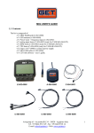
1
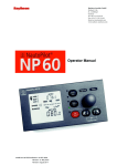
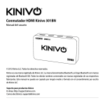
CONTENTS
GENERAL INTRODUCTION TO B&G NETWORK
INTRODUCTION TO NETWORK DEPTH
EXAMPLE SYSTEMS USING NETWORK DEPTH
SELECTING THE DISPLAY MODE
2
3
4
5
USING THE DEPTH KEY
6
SETTING THE DEPTH UNITS
THE DEPTH DATUM - D CAL
SETTING THE DEPTH DATUM
7
8
9
USING THE SIGNAL KEY
10
USING THE ALARM KEY
11
DEPTH ALARMS
ENABLING/DISABLING THE SHALLOW ALARM
ADJUSTING THE SHALLOW ALARM VALUE
ENABLING/DISABLING THE DEEP ALARM
ADJUSTING THE DEEP ALARM VALUE
THE ANCHOR ALARM
ENABLING/DISABLING THE ANCHOR ALARM
ADJUSTING THE ANCHOR ALARM LOW LIMIT
ADJUSTING THE ANCHOR ALARM HI LIMIT
610-HB-0501-04
11
12
12
13
13
14
15
16
16
USING THE LIGHTS KEY
17
SETTING THE DISPLAY LANGUAGE
18
NETWORK ALARMS
19
FAULT AND ERROR MESSAGES
20
INSTALLATION
21
SITING THE UNIT
MOUNTING THE UNIT
SPECIFICATION
21
21
23
CONDITIONS OF WARRANTY
1
GENERAL INTRODUCTION TO B&G NETWORK
The B&G Network range of instruments are designed to
be used as individual units or connected together to form
an integrated navigational system. A single network cable
is used to carry data and power between units. The latest
technology and screened cables throughout the Network
System ensure the ultimate protection from interference
between units and other systems.
All Network instruments can be linked to Network PILOT,
Network CHART, Network GPS or Network LORAN
receivers or via NMEA 0183 (v1.5) to other navigational
equipment.
INSTRUMENTS
Network SPEED
Network DEPTH
Network QUAD
Network WIND
Network TACK
Network DATA
NAVIGATIONAL AIDS
Network NAV
Network GPS
Network LORAN
LCD CHART
AUTOPILOTS
Network PILOT
610-HB-0501-04
2
INTRODUCTION TO NETWORK DEPTH
NETWORK DEPTH DISPLAY UNIT
The Network DEPTH unit measures and displays Depth
information on a large Liquid Crystal Display (LCD). The
five keys allow selection of the displayed information and
setting of the units mode, calibration factors and alarms.
It can operate as the main Network DEPTH unit either
alone or as part of an Integrated Network Instrument
System taking inputs directly from a Depth Sensor that
plugs directly into the rear of the display. It will also
operate as a repeater of depth information received via
the two Network cable tails.
The Network Depth unit has three adjustable alarms:
1. Shallow water alarm
2. Deep water alarm
3. Anchor alarm
An internal alarm buzzer will sound when an alarm
condition is met and the display will flash. The alarm is
broadcast to all other Network Instruments in an
integrated system, they will also sound their alarms and
flash their displays (except Network WIND). The Network
DEPTH unit will also indicated Network PILOT alarms and
fault conditions.
610-HB-0501-04
3
EXAMPLE SYSTEMS USING NETWORK DEPTH
Only one Network DEPTH unit should have a depth
sensor connected to it and set to transducer mode. Up to
three more Network DEPTH units can be connected on to
the system network, these must be set to repeater mode.
See SELECTING THE DISPLAY MODE.
When in repeater mode, if the data is not
being received from the system network, the
display will show OFF when a key is
pressed.
rEP Repeater mode, the unit operates as a depth
repeater using data from the system network.
610-HB-0501-04
4
SELECTING THE DISPLAY MODE
The Network DEPTH unit has two operating modes. The
correct mode must be selected for your network system
to operate properly.
trA
Transducer mode, the unit uses and displays depth
data from a depth sensor connected directly into the
display unit.
rEP Repeater mode, the unit operates as a depth
repeater using data from the system network.
Press SIGNAL
key.
610-HB-0501-04
Press SETUP key
to display the
current mode.
Press ENTER key
if the mode needs
to be changed.
Use S or T to
change mode.
Press ENTER to
memorise the
new mode.
Press SIGNAL
key to complete
the change.
5
USING THE DEPTH KEY
Press the DEPTH key to cycle through the following options:
• DEPTH M The current water depth in metres M, can
also be displayed in feet FT or fathoms FA. The unit is
factory set to metres. The depth displayed is from the
depth datum, see below.
• D CAL M The Depth Datum can be adjusted so the
displayed water depth is from the water- line, the depth
sensor (transducer) or the keel/outdrive depth. The
unit is factory set to display water depth from the
transducer.
The Network DEPTH unit can measure and display water
depth in the following ranges:
•
•
•
•
0.7 to 180 metres
2'4" to 590'
0.37 to 98.4 fathoms
Accuracy ± 2% or ± 0.2m (± 8")
610-HB-0501-04
If the Network DEPTH unit losses valid depth data, due
either the actual depth being outside the working range,
or to extreme turbulence in the water the LCD will show 3
"floating" bars. This shows that the unit is attempting to
calculate the depth and is still functioning.
6
SETTING THE DEPTH UNITS
The Network DEPTH unit can be set to display depth in
Metres M, Feet FT or Fathoms FA. The selected units are
used for displayed depth information on all Network
instruments on the entire network system.
Press DEPTH key
to display the
current depth.
610-HB-0501-04
Press SETUP
key. The depth
display will go
blank.
Press ENTER key
if the units are to
be changed.
Use S or T to
change the units.
Press ENTER key
to memorise the
change.
Press DEPTH to
display current
depth.
7
THE DEPTH DATUM - D CAL
The depth datum D CAL is an offset calibration value used
to determine the displayed information reference point. It is
added to the actual measured water depth to display the
depth from the waterline, the depth sensor (transducer) or
the keel/outdrive depth.
The Network DEPTH unit has factory set D CAL of zero,
i.e. the depth is displayed from the transducer. The D CAL
value is displayed in the same units as the depth.
610-HB-0501-04
8
SETTING THE DEPTH DATUM
D CAL zero, depth from transducer CAL TRA.
D CAL positive, depth from waterline CAL W/L.
D CAL negative, depth from keel CAL KEEL.
NOTE: If the CAL LOCK is set then the D CAL value cannot
be changed.
Press DEPTH key
to display depth
datum D CAL M.
610-HB-0501-04
Press SETUP key
to display current
datum value.
Press ENTER to
adjust the datum
value.
Use S or T to
adjust the value.
Press ENTER to
memorise the new
value.
Press DEPTH to
display the depth
datum.
9
USING THE SIGNAL KEY
Press the SIGNAL key to display a letter of merit from A to F,
this is an indication of the return echo strength. A is excellent,
F is poor.
The sea bed can have an effect on the quality of the return
echo strength, i.e. very good echoes are returned from rock,
shale and sand, however poor echoes are returned from mud.
Therefore the merit letter could be A or B for rocks but C or D
for mud.
610-HB-0501-04
10
USING THE ALARM KEY
Press the ALARM key to cycle through the following
options:
SHA A M
DEP A M
ANC A M
Shallow Alarm, when enabled it will sound if
the water depth is less than the alarm value.
Deep Alarm, when enabled it will sound if
the water depth is more than the alarm
value.
Anchor Alarm, when enabled it will sound if
the water depth is outside two alarm limits.
DEPTH ALARMS
The display will show OFF if the alarm is disabled or the
alarm value when enabled. The value will be displayed in
metres M, feet FT or fathoms FA depending on the
selected depth units.
When the alarm condition is met the unit will sound its
internal alarm buzzer and flash DEPTH M. Silence the
alarm by pressing any key.
Shallow Alarm
Factory set to 1.0m, (3.2ft, 0.5 fathoms).
Range 0 - 180m, 0 - 590ft, 0 - 98.4 fathoms.
Deep Alarm
Factory set to 10.0m, (32.8ft, 5.4 fathoms).
Range 0 - 180m, 0 - 590 ft,
0 - 98.4 fathoms.
Anchor Alarm
Factory set LOW 0.5m
(1.6/3.2ft, 0.2/.5 fathoms).
Range 0 -180m, 0 - 590 ft,
0 - 98.4 fathoms.
610-HB-0501-04
HI
1.0m,
11
ENABLING/DISABLING THE SHALLOW ALARM
Press ALARM key
to display shallow
alarm SHA A M.
Press SETUP key,
the alarm state will
be displayed.
Press ENTER key,
the display will
flash.
Use S or T to
enable/disable the
alarm.
Press ENTER to
memorise the
change.
Press ALARM
key, the value is
displayed.
Use S or T to
adjust the value.
Press ENTER key
to memorise the
new value.
Press ALARM
key, the alarm is
displayed.
ADJUSTING THE SHALLOW ALARM VALUE
Press ALARM key
to display shallow
alarm SHA A M.
610-HB-0501-04
Press SETUP key
twice, the value is
displayed.
Press ENTER key,
the display will
flash.
12
ENABLING/DISABLING THE DEEP ALARM
Press ALARM key
to display deep
alarm DEP A M.
Press SETUP key,
the alarm state will
be displayed.
Press ENTER key,
the display will
flash.
Use S or T to
enable/disable the
alarm.
Press ENTER to
memorise the
change.
Press ALARM
key, the value is
displayed.
Use S or T to
adjust the value.
Press ENTER key
to memorise the
new value.
Press ALARM
key, the alarm is
displayed.
ADJUSTING THE DEEP ALARM VALUE
Press ALARM key
to display shallow
alarm DEP A M
610-HB-0501-04
Press SETUP key
twice, the value is
displayed.
Press ENTER key,
the display will
flash.
13
USING THE ANCHOR ALARM
The Anchor Alarm uses two adjustable alarm limits. The
alarm will sound if the water is deeper or shallower, by the
amount set, than the original depth when the alarm was
enabled. This allows you to adjust your anchor chain
according to the rise and fall of the tides. The Network
DEPTH unit has a factory set low limit of 0.5m and a high
limit of 1.0m.
The anchor alarm depth limits are shown alternatively when
they are enabled and displayed using the ALARM key.
In the following example the original water depth was 3m
when the alarm was enabled. Using the factory set values,
the water depth could increase to 4m (3m + 1m) and
decrease to 2.5m (3m - 0.5m) before the alarm would
sound.
ANCH HI limit
ANCH HI Alarm
at 4.0m
1.0m
0.5m
ANCH LOW limit
3.0m depth
610-HB-0501-04
ANCH LOW Alarm
at 2.5m
14
ENABLING/DISABLING THE ANCHOR ALARM
Press ALARM
key to display
anchor alarm
ANC A M
610-HB-0501-04
Press SETUP
key, the alarm
state will be
displayed.
Press ENTER
key, the display
will flash.
Use S or T to
enable/disable the
alarm.
Press ENTER to
memorise the
change.
Press ALARM
key, to display the
anchor alarm.
15
ADJUSTING THE ANCHOR ALARM LOW LIMIT
Press ALARM key
to display anchor
alarm ANC A M.
Press SETUP key
twice to display
ANCH LOW
value.
Press ENTER key,
the display will
flash.
Use S or T to
adjust the
displayed value.
Press ENTER to
memorise the new
value.
Press ALARM key
to display the
anchor alarm.
Use S or T to
adjust the
displayed value.
Press ENTER key
to memorise the
new value.
Press ALARM key
to display the
anchor alarm.
ADJUSTING THE ANCHOR ALARM HI LIMIT
Press ALARM key
to display anchor
alarm ANC A M.
Press SETUP key
3 times to display
ANCH HI value.
610-HB-0501-04
Press ENTER key,
the display will
flash.
16
USING THE LIGHTS KEY
The Network DEPTH Display unit has 3 levels of
illumination and off, controlled by the LIGHTS key. It also
changes the illumination level of the key legends.
The LIGHTS key is always illuminated so even in complete
darkness the key can be located.
•
•
•
•
LIGHTS 0
LIGHTS 3
LIGHTS 2
LIGHTS 1
OFF
High
Medium
Low
610-HB-0501-04
17
SETTING THE DISPLAY LANGUAGE
The Network DEPTH unit can show LCD text in English or
French. To change the display language procede as follows.
Press SIGNAL
key.
610-HB-0501-04
Press SETUP
key twice to
display the
language
setting.
Press ENTER
key if the
language needs
to be changed.
Use S or T to
change the
language.
Press ENTER
to memorise the
new setting.
Press SIGNAL
key to complete
the change.
The LCD now
shows French
text.
18
NETWORK ALARMS
The Network DEPTH unit has an internal buzzer that
willsound when an alarm condition is met on a Network
unitthat has alarm functions ie. Network DEPTH and
NetworkQUAD for depth alarms and Network PILOT for
WatchAlarm and Off Course alarms. The unit will also
displaywhich alarm is activated.
NETWORK PILOT ALARM DISPLAYS
The Watch Alarm is a count-down timer with is activated at
the end of the preset count-down period. The display
alternates between the messages below.
To silence the internal alarm and return the display to
normal operation press any of the five keys.
DEPTH ALARM DISPLAY
The Off Course alarm is activated when the boat deviates
off course by a preset amount. The display alternates
between the messages below:
Depth alarms can be set for the following:
• Shallow water
• Deep water
• Anchor Watch
Check your Network DEPTH or QUAD unit to see which
alarm is activated.
610-HB-0501-04
19
FAULT AND ERROR MESSAGES
NETWORK PILOT FAULT DISPLAY
UNIT INTERNAL ERRORS
If Network PILOT should have a fault the autopilot computer
unit will send a message to all other Network Display Units.
The Network DEPTH unit will alternately display the follow
message, the actual fault will have to read from the Network
PILOT Display unit.
In the unlikely event that your Network DEPTH unit should
develop an internal error, the unit will sound it's alarm
continuously and the display will show an error number.
610-HB-0501-04
Press any of the keys to reset the error condition and
silence this alarm. In some cases the fault can be cleared
by switching off the instruments at the supply, waiting a few
moments and then switching on again. If either of these
methods do not clear the fault the error number should be
recorded. Switch off the supply and disconnect the faulty
unit. Return it with the error number to your dealer for
servicing.
20
INSTALLATION
MOUNTING THE UNIT
The display heads are supplied with a clip-in mounting
bracket which allows for easy installation, access from
behind is not necessary to secure the unit in place.
However to prevent theft and permanently fix the unit in
position, locking studs and thumb nuts are supplied.
Use the cutting template supplied to mark the centres of the
holes for the self-tapping screw, the fixing stud holes and
the mounting bracket.
•
SITING THE UNIT
All Network Instruments are designed for mounting on or
below deck. A mounting position should be selected where
they are:
•
•
•
•
•
•
Easy to read by the helmsman
On a smooth and flat surface
At least 100mm (4") from a compass
Accessible from behind for fitting locking studs if
required.
•
•
•
•
•
•
610-HB-0501-04
The template allows 4mm (5/32") between adjacent units
for the suncover, increase this distance if required to
maximum of 60mm (2 3/8") between units or 180mm (3
1/8") between centres. For greater distances between
units extension cables are available.
Use a 70mm (2 3/4") diameter hole-cutter for the
mounting bracket hole.
Use a 2.9mm for the self-tapping screw holes. Use a
5mm (3/32") drill for the locking stud holes.
Secure the mounting bracket to the bulkhead with the
self-tapping screws supplied
Fit the rubber sealing gasket around the mounting
bracket.
Screw the locking studs into the back of the display head
(if required).
Carefully pass the cable tails through the mounting
bracket hole, connect the cables to the main units.
Clip the display head into the mounting bracket.
Secure the instrument with the thumb nuts supplied.
21
INSTALLATION DATA
110.0mm
25.0mm
65.0mm
Locking stud fixings
110.0mm
Network connector
Mounting Bracket
Network and Power connector
Rubber Gasket
82.0mm
Fit the gasket
around the bracket
82.0mm
Gasket
Display
Sun cover
70.0mm hole
Bulkhead
Gasket
Mounting Bracket
Self-tapping screws
610-HB-0501-04
22
SPECIFICATION
ELECTRICAL
PHYSICAL PARAMETERS
Construction
Window
Display
Dimensions:
Weight:
High impact ABS plastic
Acrylic
Back-lit Liquid Crystal Display:
Large Digits: 28.6mm 1.12"
Small Digits: 11.5mm 0.45"
110 x 110 x 25.4mm 4 x 4 x 1"
Requires 65mm 2.6" depth behind
bulkhead for display barrel
0,3 Kg 0.66lbs
ENVIRONMENTAL
Operating Temp
Storage Temp
Humidity
Sealing
610-HB-0501-04
Power Supply
Operating Current
Protection
12V DC nominal (10 to 16V)
40mA typical, 100mA illuminated
Connect via external fuse or circuit
breaker.
CABLES AND CONNECTIONS
Connection to adjacent units is via cable tails fitted with
either a plug or a socket. Extension cables are available
from your dealer. The cable tails carry power and NMEA
data between units.
ALARM
-10 à+55°C, +14 to +1310F
@ 93%RH
-25 à+70°C, -25 to +700C
@ 95%RH
Up to 95%RH
Fully sealed front, suitable for
bulkhead cockpit mounting. Vented
barrel to prevent condensation.
Internal audible alarm. Control output for external alarm unit.
NMEA OUTPUT SENTENCES
There is no NMEA output from the Network DEPTH unit.
23