1
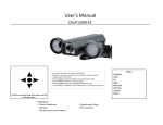
MD4 USER’S GUIDE
1.1 Contents
The kit is composed of:
- n°1 MD4 Dashboard (E-002-0000)
- n°1 GPS antenna (A-000-0000)
- n°1 Power loom + frequency input (C-004-0001)
- n°1 analog input loom (C-004-0005) (only for YAMAHA R6 KIT)
- n°1 RPM loom (C-004-0002) (only for YAMAHA R6 KIT)
- n°1 TPS loom (C-004-0006) (only for YAMAHA R6 KIT)
- n°2 rings (A-017-0000) to connect power supply
- n°1 Mini-USB cable (C-003-0004)
- n°1 CD with software + user’s guide.
E-002-0000
C-004-0005
A-000-0000
C-004-0002
C-004-0001
C-004-0006
Axiogroup srl - via ponticelli,134 – 36020 - Agugliaro Italy
Tel. +39 0444 89 21 49 - Fax +39 0444 89 28 14
E-mail: [email protected] - Web: www.getdata.it
1
1.2 Connections
E
D
C
B
A
Follow the following steps to connect the system:
1- Install MD4 device onto the vehicle.
2- Connect the Power loom (C-004-0001) to connector A on the rear of the
device. (Attention: tighten with your hands is enough)
3- Connect the analog input loom (C-004-0005) to connector C on the rear of
the device. (Attention: tighten with your hands is enough)
4- Connect the GPS antenna (A-000-0000) to connector D on the rear of the
device. (Attention: tighten with your hands is enough). See section 1.2.1.
5- If present, connect the RPM loom (C-004-0002) to the Power loom (C-0040001).
Attention: the RPM loom is different according to the type of use.
6- If present, connect the TPS loom (C-004-0006) to the analog loom in
input #1 (C-004-0005).
Attention: the TPS loom is different according to the type of use.
7- Connect the 2 wires of the Power (see Power label on it) to the motorcycle
battery (see section 1.2.2).
8- On the left of the device, there is the USB port for PC connection.
Axiogroup srl - via ponticelli,134 – 36020 - Agugliaro Italy
Tel. +39 0444 89 21 49 - Fax +39 0444 89 28 14
E-mail: [email protected] - Web: www.getdata.it
2
1.2.1 GPS antenna connection
Fix the GPS antenna connector to connector D of the dashboard avoiding overstrength. Do not use a wrench but simply fix it with your fingers.
Keep the antenna cable away from electromagnetic source, i.e. make sure the
cable is away from the engine, ignition coil, spark plugs and wires.
Electromagnetic disturbances may disturb the GPS signal, decreasing its
performance.
The GPS antenna must be set outside of the vehicle. Any obstacle near the GPS
antenna could cause disturbances, specifically during download. This is shown by a
bad track drawing with inappropriate peaks or spikes.
NEVER roll the antenna cable around other cables such as power, RPM, …to avoid
disturbances.
Una cattiva ricezione dell’antenna può causare errori sul calcolo dei tempi sul giro o il
non rilevamento di traguardi o intertempi.
In case of bad antenna reception, only sensors data will be visible.
Sometimes, GPS satellites operator disable their network, causing reception blackout
on all GPS-based devices.
1.2.2 Connection to motorcycle battery
We recommend to use the small rings to connect the 2 wires to the power loom
(C-004-0001-20) to the battery.
In case of 2-stroke bikes, or if no battery on board, please order the battery kit
including charger.
ATTENTION: The red wire must be connected to the battery POSITIVE
end, Black wire to NEGATIVE end.
Axiogroup srl - via ponticelli,134 – 36020 - Agugliaro Italy
Tel. +39 0444 89 21 49 - Fax +39 0444 89 28 14
E-mail: [email protected] - Web: www.getdata.it
3
1.2.3 RPM and TPS connection
For RPM and TPS, please contact your dealer to make sure what RPM and TPS
are needed for bike model.
Indeed, you may need wires with a conditioning chip to avoid any disturbances.
Please refer to application sheet attached.
1.2.4 Connection procedure A
Cut the wire coating (making sure you do not cut the copper conductor) and
twist the uncoated end of the wire. Then weld with a soldering iron.
1.2.5 Other sensors applications.
Please refer to the specific sensor datasheet included in the delivery.
Axiogroup srl - via ponticelli,134 – 36020 - Agugliaro Italy
Tel. +39 0444 89 21 49 - Fax +39 0444 89 28 14
E-mail: [email protected] - Web: www.getdata.it
4
How to use the MD4 device (Firmware 1.591)
All steps to download data onto your PC are described in the MX1 user’s guide.
Please print it for ease of use.
Switching on:
Press on SET to switch it on and see the menu page.
In the menu page you will see the following functions:
Watch:
To see system status live. Once selected, it shows sensor and
system data live, e.g. Power (VBAT), Speed (SOGK or VEL), n°
of connected satellites (N°SAT), Altitude (ANTA)
Logging:
Tracks:
To launch data acquisition. By default, it is a manual launch.
But you can set an automatic start in OPTIONS with RPM or
SPEED values
Track settings. Used also to open tracks from the folder
where a max 100 tracks can be recorded (with 5 intermediate
sectors each). Latest tracks are available for download on our
website.
Also shows current track.
•
CUR: Current track.
•
OPEN TRACK
Axiogroup srl - via ponticelli,134 – 36020 - Agugliaro Italy
Tel. +39 0444 89 21 49 - Fax +39 0444 89 28 14
E-mail: [email protected] - Web: www.getdata.it
5
Calibrations
Alarms:
Files:
Options:
•
DELETE TRACK
•
CREATE TRACK: To create a new track directly on the
MD4, without PC.
•
CLEAR BEST: Remove best lap from device memory.
•
REFT: Set a reference time. On each finish line passage,
the device shows the difference between current lap and
reference lap.
Channels and sensors calibration.
Alarms management.
File management (Open, Delete, …).
Basic settings such as:
• Logging: Acquisition start options. You can choose manual
or via RPM with default threshold at 1.500 laps for start and
500 for stop, or via GPS speed with start threshold at
30KPH and stop at zero KPH. (If speed-based, the
acquisition stops each time the vehicle is at speed = 0.
•
Backlite: LCD backlight ON-OFF. Default is OFF, if you
set it ON, backlight will be active every time the system is
on.
•
SET INFO: Allows setting a number to identify the system when
downloading data. For instance, if there 3 drivers in the team,
each one will have a number that is shown in the file name.
SET DATE: Set date and time. Manual mode by default. The
number is enhanced. Use arrows to change the number and
press SET to go to next number. Press MENU when ready to
exit DATE mode. Use arrows to select TIME and proceed in the
same way. Press MENU to exit.
Alternatively, the automatic mode (AUTO) can do for you. Just
set the number of hours ahead (positive +) or behind (negative
-) Greenwich Mean Time (GMT). E.g.: Germany is +1). Next
time you will switch your MD4 on, time will be update
automatically.
•
•
•
CREDITS: shows device firmware version. Latest update
available on our website www.getdata.it
MD4 RESET: Reseti alarms, finish line, options such as
LOGGING – BACKLITE – BEST TIME, …
Axiogroup srl - via ponticelli,134 – 36020 - Agugliaro Italy
Tel. +39 0444 89 21 49 - Fax +39 0444 89 28 14
E-mail: [email protected] - Web: www.getdata.it
6
Attention: this function is mandatory in case of firmware update.
After selecting MD4 RESET, press SET on each question.
When the MD4 is switched on, the right blue led remains on until the device
has established full connection with the satellite network. This takes about 1
minute and is done automatically.
If you are indoor, this led will remain on until you go outdoor.
This led goes off if you start acquisition.
Switching the MD4 off
Just press on MENU and SET simultaneously.
Switching backlight on for night-time use.
In MENU, use arrows to go to OPTIONS, then SET. Use arrows to go to
BACKLITE and choose ON or OFF with SET.
Press on MENU to go back to menu.
For a better reading during daytime, we recommend to set it off.
“WATCH” function:
All GPS data can be viewed.
As for sensor data, they will be viewed only after setup as follows.
TPS
Throttle position (if included in setup)
RPM
Round per Minute (if included in setup)
SPEED
also known as SOGKM, KMH, KPH
ANTAL altitude
NSAT
n° satellites connected to the system
TPS channel calibration:
Press on Menu. With arrows, choose Calibrations and press SET.
Press SET on the channel you connected the TPS wire (AD1).
Press SET on TPS item.
Keeping your throttle to 0 (Check that bike board is on), press SET to insert the
min value.
Keeping the throttle full up 100% (The bike is off but the board is on), press
SET.
Press MENU to go back.
Axiogroup srl - via ponticelli,134 – 36020 - Agugliaro Italy
Tel. +39 0444 89 21 49 - Fax +39 0444 89 28 14
E-mail: [email protected] - Web: www.getdata.it
7
Calibration is done and can be monitored from the Watch page.
Axiogroup srl - via ponticelli,134 – 36020 - Agugliaro Italy
Tel. +39 0444 89 21 49 - Fax +39 0444 89 28 14
E-mail: [email protected] - Web: www.getdata.it
8
RPM channel calibration
Press on MENU.
With arrows, choose Calibrations and press SET.
With arrows, choose IC1 and press SET.
With arrows, set the number of phonic wheel teeth for 2 crankshaft laps in case
of 4-stroke engine, and e press SET. (for YAMAHA R6, it is 4)
Press MENU twice.
Calibration is done and can be monitored from the Watch page.
Attention: In the WATCH page, the limiter value will not be shown and
the leds will not be active. The central red leds that show the limiter value
will be active only in data acquisition mode.
Spark RPM with clip
Press on MENU.
With arrows, choose Calibrations and press SET.
With arrows, choose IC1 and press SET.
Select RPMSPARK and insert relevant value.
For 2-stroke engines: COEFFICIENT 18.4 and OFFSET 184
These values can be changed at any time according to your needs.
Attention: We recommend that the conditioning circuit should be as far as
possible from the ignition coil and spark plug in order to improve the
signal quality.
Do not roll up the extra wire near the spark plug or coil but in a protected
area instead to avoid disturbances.
We also recommend to keep the RPM wire away from the GPS antenna.
Analog channels 1-2-3-4 calibration
Any 0-5 Volt analog sensor can be used on these channels, e.g. suspension
potentiometers, NTC temperature sensors, K-type sensors, Lambda probes
whether sold by GET. You can also buy other sensors on the market but then
you need to use our MX1 software and insert the calibrations found in the
appropriate sensor data sheet
Axiogroup srl - via ponticelli,134 – 36020 - Agugliaro Italy
Tel. +39 0444 89 21 49 - Fax +39 0444 89 28 14
E-mail: [email protected] - Web: www.getdata.it
9
For GET sensors, all calibration values are already set and all you need to do is
select the sensor you want to use.
These default GET sensors are::
TK = Thermocouple sensor for exhaust temperature –20° + 1000°
NTC = Air-Oil-Air temperature sensor -40° + 150°
TPS = Throttle position sensor
POT = Linear potentiometer (e.g. for suspensions)
LISTO = Lambda probe with reading value Lambda (9.2)
LAFR = Lambda probe with reading value AFR fuel e.g. 14.0
RPM = Round per Minute from PICK UP
RPM SPARK = Round per Minute from spark clip
Any other sensor can be added via PC.
Attention: if you wish to perform a channel calibration through our MX1
software, you will have to use the CUSTOM function into the MD4 and send
the setup from PC to MD4.
Position sensor calibration - Potentiometer
Connect the sensor to one available channel: 1-2-3-4.
Press on MENU.
With arrows, choose Calibrations and press SET.
With arrows, select the channel where your sensor is connected (AD1 or AD2
or AD3 or AD4) , and press SET.
With arrows, got to POT and press SET.
“CURRENT” means the sensor electrical value.
With arrows, go to “LEN” to insert the sensor length, e.g. 125 mm. Press SET.
Press SET again to confirm the “zero” position of the sensor. Of course you
need to have your sensor physically at “zero” position.
Press SET to confirm.
Press MENU and select WATCH to check the zero position.
This setup can also be done through our MX1 software. See MX1 instructions.
Axiogroup srl - via ponticelli,134 – 36020 - Agugliaro Italy
Tel. +39 0444 89 21 49 - Fax +39 0444 89 28 14
E-mail: [email protected] - Web: www.getdata.it
10
Track settings (finish line and intermediates)
Press on MENU, then go to TRACKS. Here you can do 3 operations:
CREATE TRACK, OPEN TRACK, DELETE TRACK.
If your track is in the list, choose it through MENU/TRACK/OPEN TRACK. If not in
the list, you will have to create it.
CREATE TRACK (from data acquisition)
Press MENU and go to LOGGING. Check that satellites are connected first
(Blue led is off). Start acquisition by pressing SET.
Drive one track lap (start from box, perform a complete lap but go out the
second lap is completed).
Once ended, press SET to stop acquisition. Press MENU.
Go to TRACK and press SET.
Wait for track view. Finish Line and SP1-2-3-4 sectors also appear.
Press SET when FL is enhanced, and go to the position you want with arrows.
Press SET to confirm.
For other sectors settings, go to SP1.
Press SET and put it where you want with arrows.
Press SET to confirm.
Same thing for other sectors. At the end, press MENU.
From now on, and until a new track is created or loaded, all laps you run will
be split according to these recorded settings, even if files are removed from
memory with “CLEAR MEMORY” from FILE page.
BUT these settings will be erased if you choose the SOFT RESET option from
the OPTIONS page.
ATTENTION: Sectors must be set from 1 to 4 in order.
Axiogroup srl - via ponticelli,134 – 36020 - Agugliaro Italy
Tel. +39 0444 89 21 49 - Fax +39 0444 89 28 14
E-mail: [email protected] - Web: www.getdata.it
11
OPEN TRACK
To load track library, switch you MD4 on and go the MENU page. Connect the
MD4 to your computer. Right-click on an MD4 setup and do Synchronize
library.
On the MX1 software, right-click on TRACK window and choose LIBRARY.
You can also update your library by downloading the new tracks from our
website www.getdata.it download area.
The tracks that we give you have a finish line and 3 or 4 sectors according to
the track.
To download the tracks from our website:
Go to www.getdata.it
Go to DOWNLOAD
Go to TRACKS
Download the zip file into the MX1 folder. This folder is found in:
Your computer
-Disk C
-programs
-MX1.
DELETE TRACK
Just select a track to delete it.
Track setting through PC
Make your track run. Download data on your computer.
Set finish line and sectors (see MX1 software user’s guide), save track and add
it to the library (when asked after saving).
From the TRACK window, right-click and choose Library to change, save and
apply tracks to the current sessions.
Then switch your MD4 on and go to MENU page. Connect the MD4 to your
computer. Right-click on an MD4 setup and do Synchronize library.
Axiogroup srl - via ponticelli,134 – 36020 - Agugliaro Italy
Tel. +39 0444 89 21 49 - Fax +39 0444 89 28 14
E-mail: [email protected] - Web: www.getdata.it
12
Launching data acquisition
You can choose manual launch or via RPM with default threshold at 1.500 laps
for start and 500 for stop, or via GPS speed with start threshold at 30KPH and
stop at zero KPH. (GET recommends either manual start or RPM-based
start since the speed-based start means a stop every time the bike is at a
standstill, i.e. speed = 0).
ATTENTION: RPM or SPEED –based start are available only if the MD4
is on page MENU or session REPORT. If the MD4 is on WATCHALARM-CALIBRATION-TRACK-OPTIONS, no automatic start will be
done.
Time, intermediates, best lap and best intermediate alarms
When cutting the finish line, the dashboard gives you the lap time and the
orange led goes on if it is your best lap.
This lap time keeps on until you cut the finish line again.
When cutting the intermediate sector line, the dashboard shows (for 3 seconds)
the how far ahead or behind you are until this point against your best lap.
Here again, the orange led goes on to show you your best intermediate time.
These best times are kept in memory until you press the CLEAR BEST option.
Session report:
At the end of each session, you can see:
Number of track laps
Best lap
Best sectors and Theoretical Best lap (TH)
Min and max values for each recorded channel
Lap times
Axiogroup srl - via ponticelli,134 – 36020 - Agugliaro Italy
Tel. +39 0444 89 21 49 - Fax +39 0444 89 28 14
E-mail: [email protected] - Web: www.getdata.it
13
Reading session reports from FILES.
Press MENU and go to FILES.
Go to OPEN FILE and press SET ( Do not press CLEAR MEMORY!).
Select the date and press SET.
Select your session according to date and time and press SET to see it.
Press SET to browse REPORT pages.
Press MENU to exit.
In case of no sectors, the second page displays “TH NA” (Theoretical Best Not
Available).
Alarm setting:
Press MENU. Go to ALARMS and press SET.
5 alarm settings are available.
Choose one with arrows. Press SET.
With arrows, choose sensor channel. Press SET.
Next to CH (Channel), you find the sensor name as per setup.
O the second line, insert the threshold value THR. Press SET.
Select MORE or LESS or EQUAL. Usually, one selects MORE to know when
threshold value is exceeded. Premere SET per confermare.
Set the signal type by choosing FIXED or BLINK.
Select led colour. Press SET.
Press MENU to end.
To change the gear threshold, choose the IC1 for RPM and set the threshold as
described above (e.g. 16.000 laps). We recommend to set the red signal on
BLINK mode.
ATTENTION: to disable alarms, just press SET. Alarm will be disabled until a
new data acquisition is launched.
Live data on the MD4.
During acquisition, you can see lap time, speed “KPH” and any other channel.
Just browse options with arrows.
Axiogroup srl - via ponticelli,134 – 36020 - Agugliaro Italy
Tel. +39 0444 89 21 49 - Fax +39 0444 89 28 14
E-mail: [email protected] - Web: www.getdata.it
14
Data analysis with MX1 software.
Connect the MD4 to your computer through the USB cable and follow
instructions.
Data download is only available when the MD4 is on MENU page.
We recommend to switch your bike off before downloading.
PLEASE SEE MX1 SOFTWARE USER’S GUIDE FOR DATA
ANALYSIS.
Time accuracy in MD4.
Thanks to our MX1 software processing, lap times are recalculated and become
more accurate. As a result, you may find some difference between lap times
shown by the MD4 and those shown on your computer.
How to update MD4 firmware
(Your MD4 current firmware version can be seen after switching your device and then pressing on
the left arrow)
1. Save any data recorded into your MD4 on your computer.
2. Switch MD4 device on and connect it to your computer via USB cable.
3. Run “fwupdate” file (Power must keep on during this phase).
4. Select “Update” (you may have to try several times) until “Transfer completed!” appears.
5. Now you can turn power off for a few seconds (removing the MAIN cable for instance).
6. Switch MD4 device on.
7. When and only when device shows “NO SETUP”, send a setup using into the MD4
using the MX2 software on your PC (See MX2 user’s guide for more info)
8. Select OPTIONS from the main MENU.
9. Select MD4 RESET, then choose SET upon “CONFIRM?” request, and then SET
again upon “PRECAL?” request. Select MD4 RESET again, then choose SET upon
“CONFIRM?” request and then MENU upon “PRECAL?” request.
10. Press MENU.
11. Once firmware is updated, all calibrations will have to be made again.
Axiogroup srl - via ponticelli,134 – 36020 - Agugliaro Italy
Tel. +39 0444 89 21 49 - Fax +39 0444 89 28 14
E-mail: [email protected] - Web: www.getdata.it
15