1
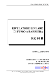
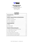
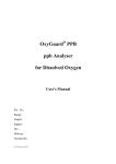
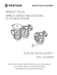
POINT FOUR™ RIU3
REMOTE MONITOR/CONTROLLER
INSTALLATION AND
USER’S GUIDE
IMPORTANT SAFETY INSTRUCTIONS
READ AND FOLLOW ALL INSTRUCTIONS
SAVE THESE INSTRUCTIONS
2
CUSTOMER SERVICE / TECHNICAL SUPPORT
If you have questions about ordering Pentair Aquatic Eco Systems replacement parts, and products, please use the following contact information:
Customer Service (8 A.M. to 4:30 P.M. — Eastern and
Pacific Times)
Technical Support
Phone: (800) 831-7133
Phone: (877) 347-4788
Apopka, Florida (8 A.M. to 4:30 P.M. ET)
Fax: (800) 284-4151
Web site
Visit www.pentairaes.com or www.pointfour.com to find
information about Pentair products.
TABLE OF CONTENTS
OVERVIEW
3
SYSTEM COMPONENTS
4
SYSTEM WIRING
5
TYPICAL RIU WIRING CONFIGUATIONS
6
RIU3 FRONT PANEL
7
TYPICAL RIU SYSTEM SETUP
8
RIU3 OPERATION
9
CONTROL BLOCK OPERATION
17
PROBE CALIBRATION
19
APPENDIX
21
NOTES
26
P/N 354610 Rev. B 9/17/13
POINT FOUR™ RIU3 Remote Monitor/Controller Installation and User’s Guide
3
OVERVIEW
This manual is designed as a guide to assist users in becoming familiar with the various functions of the RIU3 (remote interface
unit). Each section of this manual is set up to easily guide users through all stages of installation, setup and maintenance.
Starting from unpacking and inspecting the box, this manual will explain all parts and functions of the system to allow users
to get the most out of the RIU3 for all their system monitoring needs.
The PT4 RIU3 is a field mounted single sensor transmitter/controller. The unit is compatible with a variety of water
quality probes such as dissolved oxygen, temperature and pH. For a full list of compatible probes, see Table1. The
RIU3 is equipped with a large font 8 x 2 backlit display so the user can view the sensor readings . The unit contains two
SPDT 10amp relays to be used for alarm and/or control outputs. The control blocks can be configured as described
on page 17 Probe calibration can also be done via the RIU3 interface as described on page 19.
The RIU3 uses IP67-rated cable glands for the power, data and probe connections, sealing the unit for wet
environments. Although the RIU will function as a standalone controller, up to 99 units may be daisy chained for a
network connection. This allows the user to collect, manipulate and control all of the data via the PT4 LC Controller
or using the PT4 Sync HMI Software (Windows Based).
Table 1: RIU3-compatible probes
Probe Description
Manufacturer
Parameters
Signal Type
Item Number
Galvanic DO/Temp
OxyGuard
%Sat, mg/L, DegC
mV, Thermistor
1OXYC310
Galvanic DO
OxyGuard
%Sat or mg/L
mV
1OXSP001
Optical DO
In-Situ
%Sat or mg/L
4-20 mA
1ISRD001
Temperature
OxyGuard
DegC
4-20 mA
1OXSP602
Temperature
Pentair
DegC
mA
1PTPR010
TGP
Pentair
TGP (mmHg, %, ΔP), BP (mmHg) mV
1SSP0021
pH
Sensorex
pH
4-20 mA
1SXS8000pH
ORP
Sensorex
mV
4-20 mA
1SXS8000
Salinity
OxyGuard
ppt
4-20 mA
1OXSP304
Dissolved CO2 w/ transmitter
OxyGuard
mg/L
4-20 mA
1OXYCO475
Toroidal Conductivity w/
transmitter
Sensorex
uS/cm
4-20 mA
1SXTCS3020
1SXCOTCSMA
* Other probes available upon request
Weatherproof Enclosure:
NEMA 4x
IP65 Rated
Easy to Read:
Large Font
Backlit Display
User Selectable Control:
Tank Side Sensor Calibration
Local Control Setup
Alarm Setpoint
PID Function
Multiple System
Congurations:
Single Unit Controller
or
Multi-linked Network
(up to 99 units)
2 Relay Outputs:
Alerting Alarm Conditions
via Light, Siren or SMS
and
Dosing Oxygen or
Controlling Blowers
Various Sensor Input Types:
Oxygen
Temperature
Bp
pH/ORP
Salinity
TGP
Optical DO
POINT FOUR™ RIU3 Remote Monitor/Controller Installation and User’s Guide
4
SYSTEM COMPONENTS
System Components
System Specifications
1)
2)
3)
4)
5)
6)
1) Power: 12-24 VDC, 180 mA max
2) Auxiliary power for loop-powered probes: Onboard
isolated 24 VDC loop power supply
3) Input: Inputs are factory-configurable for probes listed
in Table1. Additional probe types are available upon request
4) Outputs: Two SPDT 10 Amp relays – user configurable,
RS-485 MODBUS communications
5) Environmental: IP67 water tight enclosure, sealed cable
glands
6) Dimensions: 125x125x75 mm
RIU LCD Display : 4 x 20 Backlit Alpha Numeric
4-Button Foil Switch
PG9 Cable Gland for Probe Input
PG9 Cable Glands for Power and Data connections (x2)
PG7 Cable Glands for Relay Outputs (x2)
Optional Enclosure Mounting Feet (x4)
1
2
6
3
5
POINT FOUR™ RIU3 Remote Monitor/Controller Installation and User’s Guide
4
5
SYSTEM WIRING
1. Ch1 input connector
i. A 2 pin connector for the first channel for a probe input. Required only for certain probe types, such as a Dissolved oxygen/
Temperature probe.
2. Ch2 input connector
i. A 2 pin connector for the second channel for a probe input. Required only for probes with multiple channels, such as a
Dissolved oxygen / Temperature probe.
3. Isolated DC output for auxiliary probe power
i. A 2 pin connector used to provide 24 VDC isolated auxiliary probe power. This can also be factory-configured for 10 VDC
as necessary. See page 6 for wiring information.
4. Auxiliary RS485 input connector
i. A 2 pin connector for RS485 probe inputs.
5. Power & RS485 inputs
i. 5 pin connectors. Pins 1 and 2 are used to connect DC power to the RIU3. Pins 3 and 4 are used to connect the Modbus
RS485 signal to the RIU3. Pin 5 is used to connect the shield of the cable to the RIU3 ground. See page 6 for wiring information.
6. Data Tx & Rx LEDs
i. These LEDs indicate Modbus RS485 communications. The Rx LED will blink when a Modbus message is received by the
RIU3 and the Tx LED will blink when a Modbus message is transmitted by the RIU3.
7. Relay output connectors
i. 3 pin connectors used to connect the relay output to an external device. Normally open or normally closed configurations
can be used. See page 6 for wiring information.
8. SPDT relays
i. Single pole, double throw relays rated for up to 24 VDC , 10 A. The relay status is controlled by RIU3 control blocks, which can
be configured through the Control menu using the 4-button foil switch. See page 17 for control block configuration information.
POINT FOUR™ RIU3 Remote Monitor/Controller Installation and User’s Guide
6
TYPICAL RIU WIRING CONFIGURATIONS
Typical RIU Wiring Configurations
1. Wiring for use with PT4 LC or other SCADA system
2. Wiring for use with a PC
Warning: If the Data and Power wires are not connected to the appropriate terminals, damage to the RIU3 may occur. This will
void the warranty. Please ensure all connections are correct before powering up the unit.
Relay Wiring Examples
1. Dry Contact – Normally Open or Normally Closed
2. Live Contact – RIU or External Power
POINT FOUR™ RIU3 Remote Monitor/Controller Installation and User’s Guide
7
RIU3 FRONT PANEL
1. LCD Display
i. A 2x8 Backlit LCD display.
2. “Up” Button
i. Scrolls up through menu options or input characters, or in the main menu, toggles between display parameters.
3. “Down” Button
i. Scrolls up through menu options or input characters, or in the main menu, toggles between display parameters.
4. “Return” Button
i. This button can be held for 3 seconds to enter into the RIU3 configuration menu. While in the configuration, this can be
pressed to return to the previous menu page.
5. “Enter” Button
i. This button is used while in the configuration menu to confirm a selection or user input. See page 9 for more information
about navigating the RIU3 menu.
POINT FOUR™ RIU3 Remote Monitor/Controller Installation and User’s Guide
8
TYPICAL RIU SYSTEM SETUP
MULTI-LINKED NETWORK
SINGLE UNIT CONTROLLER
POINT FOUR™ RIU3 Remote Monitor/Controller Installation and User’s Guide
9
RIU3 OPERATION
The main screen of the RIU3 displays the current values read from the probe.
Using the up and down keys toggles between additional probe values and shows the status of the relays either being on or off.
Warnings conditions are also displayed on the Main screen
Holding down the return arrow for three seconds brings you into the settings menu.
The settings menu allows you configure multiple values and parameters such as alarm conditions, relay control type, probe
calibration, backlight set up and system diagnostics.
The following chapter will discuss the basic operational features and menu structure of the RIU3.
Additional chapters in this manual will explain advanced features such as configuring relay control types, two point calibration,
and troubleshooting.
MAIN DISPLAY
Main Display
PV Values
Error Display
Error Condition
If more than 2 PV
values: displayed 2
per screen
<Toggled every 2 sec>
Error Types:
Example
100% Sat
Highest
Priority
8.9 mg/L
Relay Status
Example
R1 = ON
R2 = OFF
Hold for > 3 sec
Selection Menu
POINT FOUR™ RIU3 Remote Monitor/Controller Installation and User’s Guide
Lowest
Priority
[
[
[
[
ERROR
Low Volt
ERROR
High Amp
mV Trim
Required
Selftest
Required
10
SELECTION MENU
SELECT:
External Chs
External Chs
SELECT:
Calibration
Calibration
SELECT:
Control
Control
SELECT:
Diags
Diags
SELECT:
Setup
Setup
SELECT:
Exit
Main Display
IF YOU DO NOT TOUCH ANY
KEYS AFTER 60SEC THE UNIT
WILL REVERT TO THE
MAIN DISPLAY
PRESS THE RETURN BUTTON
FROM ANY SCREEN
WITHIN THE DASHED LINE
TO REVERT TO THE
MAIN DISPLAY
Page 2
POINT FOUR™ RIU3 Remote Monitor/Controller Installation and User’s Guide
11
EXTERNAL CH MENU
External channels
are values required
by the RIU3 that it
does not produce.
Example: BP is a required
input value for an RIU3
configured for DO readings
SET CH:
760 (CH Value Displayed)
Other EXT Chs displayed
if any
Enter EXT value
Enter EXT value
Exit
Selection Menu
Changing the Values
Example Ext XXX CH:
BPT - Default Value 760
TEMP - Default Value 20
SAL - Default Value 0
XXX CH
####
Press the up or down arrow to change the value (0-9)
Press the check to go to the next digit
Press the return key to go to the previous digit.
Pressing the return key from the 1st digit returns to the menu.
IF YOU DO NOT TOUCH ANY
KEYS AFTER 60SEC THE UNIT
WILL REVERT TO THE
MAIN DISPLAY
PRESS THE RETURN BUTTON
FROM ANY SCREEN
WITHIN THE DASHED LINE
TO REVERT TO THE
SELECTION MENU
Page 3
POINT FOUR™ RIU3 Remote Monitor/Controller Installation and User’s Guide
12
CALIBRATION MENU
Calibration
Sub Menu
CAL CH:
Oxy (Process Variable)
Other Cal Chs displayed
if any
Calibration
Sub Menu
CAL CH:
Exit
Menu Selection
Calibration Sub Menu:
Example of selected Ch displayed
mg/L
1 Pt Cal
mg/L
2 Pt Cal
mg/L
Exit
1 Point Calibration
Procedure
2 Point Calibration
Procedure
CAL CH:
Oxy (Process Variable)
PRESS THE RETURN BUTTON
FROM ANY SCREEN
WITHIN THE DASHED LINE
TO REVERT TO THE
SELECTION MENU
Page 4
POINT FOUR™ RIU3 Remote Monitor/Controller Installation and User’s Guide
13
CONTROL MENU
Select Control Block:
#1
CB
1: Oxy / mg/L
Other Control Blocks
displayed if any
CB 1
Exit
Control Block channel:
Sensor name toggled every
second with engineering units
In this example: “Oxy” / “mg/L”
Configure
Control Block
Configure
Control Block
Menu Selection
PRESS THE RETURN BUTTON
FROM ANY SCREEN
WITHIN THE BLACK
DASHED LINE
TO REVERT TO THE
SELECTION MENU
Page 7
POINT FOUR™ RIU3 Remote Monitor/Controller Installation and User’s Guide
14
CONTROL MENU
Configure Control Block:
1:
Type
Control
1:
Type
Control / Alarm
<
1:
Ch In
Oxy / mg/L
1:
Ch In
Oxy/%Sat
<
1:
Relay
Relay 1
1:
Relay
Relay 1
<
CB 1
High Setpoint
Changing the Values
View / change:
High Setpoint
1: Hi SP
###ay2
CB 1
Low Setpoint
View / change:
Low Setpoint
CB 1
Delay On
View / change:
Delay On
CB 1
Delay Off
View / change:
Delay Off
CB 1
Action
View / change:
Action
Press the up or down arrow to change the value (0-9)
Press the check to go to the next digit
Press the return key to go to the previous digit.
Pressing the return key twice from the 1st digit returns to the menu.
<
PRESS THE RETURN BUTTON
FROM ANY SCREEN
WITHIN THE RED DASHED
LINE TO REVERT TO THE
CONTROL MENU ABOVE
Page 8
POINT FOUR™ RIU3 Remote Monitor/Controller Installation and User’s Guide
15
DIAGNOSTICS MENU
[
Ch1: mV Values
Ch2: mV Values
Ch 2 mV
pass/fail Status
Total Modbus
(Net) messages
COM 1 & 2
pass/fail Status
Total Modbus
(Net) errors
I2C BUS
pass/fail Status
Keypad
pass/fail Status
EEPROM
pass/fail Status
Relay
pass/fail Status
RTC
pass/fail Status
Input Power
I =
___mA
V=
___V
[
Ch 1 mV
pass/fail Status
DIAGS
Exit
* Refer to Diagnostics Table for troubleshooting - TBD
PRESS THE RETURN BUTTON
FROM ANY SCREEN
TO REVERT TO THE
SELECTION MENU
Page 9
POINT FOUR™ RIU3 Remote Monitor/Controller Installation and User’s Guide
16
SETUP MENU
SETUP
Net ID
View / change:
Net ID
SETUP
Backlight
View / change:
Backlight options
SETUP
Low Voltage
View / change:
Low Voltage
SW REV
RIU0###
SETUP
Exit
Menu Selection
PRESS THE RETURN BUTTON
FROM ANY SCREEN
WITHIN THE DASHED LINE
TO REVERT TO THE
SELECTION MENU
Page 10
POINT FOUR™ RIU3 Remote Monitor/Controller Installation and User’s Guide
17
CONTROL BLOCK OPERATION
The RIU3 control blocks take inputs from the probe parameters and control the state of the relays according to some
user-selected set points. The user can configure the input parameters, control type, set points, delays and output relays
for each control block. The user-selectable parameters are described in more detail below.
User-Selectable Control Block Parameters
1)Type
The Type can be set either to Control or Alarm. In alarm mode, the relay output behaves as described in Figure 1.
In control mode, the relay output behaves as described in Figure 2
If the process value (PV) is within the user defined high and low
set points the system condition is normal. If the process value (PV)
fluctuates out of the alarm bandwidth (above the high set point or
below the low set point) the system will go into alarm.
This is indicated on the bottom left corner of the home screen by
flashing the word “ALARM”. This is also indicated on each individual
channel by the alarm symbol.
A delay time can be added to the setpoint. (E.G. A fish/plant touches
the probe, sending the conditions out of the normal bandwidth,
resulting in false alarm conditions. The delay time allows the conditions to return to within the normal bandwidth.
Figure 1: Alarm Mode operation
If the process value (PV) is within the user defined high and low
set points the system condition is normal. If the process value (PV)
fluctuates below the low set point the system will go into a control
situation. This turns on (or off depending on normal conditions) a
relay. The relay will remain on until the process value (PV) reaches
the high set point at which point it will switch off.
The process can be reversed so that a relay turns on when the process value (PV) fluctuates above the high setpoint, depending on
the customers needs.
This is indicated on each individual channel by the orange RLY ON
indicator.
A delay time can be added to the setpoint. (E.G. A fish/plant touches
the probe, sending the conditions out of the normal bandwidth,
resulting in false control conditions. The delay time allows the conditions to return to within the normal bandwidth. A delay can also
be added to the high setpoint which allows the system overdose,
which may be applicable in some cases.
Figure 2: Control Mode operation
POINT FOUR™ RIU3 Remote Monitor/Controller Installation and User’s Guide
18
2) Ch In
This is the input parameter for the control block. The user will have the option to select from all available parameters for
the specific probe being used.
3)Relay
This is the output relay for the control block. The user will have the option to select between Relay 1 and Relay 2.
4) Hi SP
This is the high set point as described in SectionAbove.
5) Lo SP
This is the low set point as described in SectionAbove.
6) Delay On
The delay on defines how long in seconds the control block will be in Alarm or Control status before the relay output is
activated.
7) Delay Off
The delay off defines how long in seconds the control block will be out of Alarm or Control status before the relay output
is deactivated.
8)Action
The user will have the option to select between High and Low. When set to low action, the control block will behave as
described on page 17. When in set to high action, the control block will behave inversely to what is described on page 17.
POINT FOUR™ RIU3 Remote Monitor/Controller Installation and User’s Guide
19
PROBE CALIBRATION
The calibration procedure will vary depending on the type of probe being used. In general, either 1-point or 2-point calibrations
can be done. Depending on the probe type, 1 or 2 –point calibrations may be recommended.
PV=(V_raw-Offset)×Slope
PV : Process variable – this is the value that is displayed on the main screen with the appropriate engineering units.
Vraw : Raw voltage input – this is the raw voltage value measured by the RIU3 from the probe.
Offset : The offset value is calculated by the RIU3 during calibration.
Slope: The slope value is calculated by the RIU3 during calibration.
To perform a typical 1-point calibration, the user places the probe in an environment with a known value for the measured
parameter. The user then enters the known value into the RIU3 and completes the calibration. The RIU3 will then calculate
the Offset value so the PV matches the value that the user entered for the 1-point calibration.
To perform a typical 2-point calibration, the user places the probe in an environment with a known value for the measured
parameter. The user then enters the known value into the RIU3 and captures the first calibration point. Next, the user places
the probe in a different environment with a different known value for the measured parameter. The user enters the know
value into the RIU3 again and captures this value. The calibration then completes by calculating both the Slope and the
Offset so the PV matches user entered values with the captured raw voltage inputs.
The calibration procedure is slightly different for galvanic dissolved oxygen probes. Since these probes have a true zero, the
Offset is always zero. In this case, it is never necessary to complete a 2-point calibration. During a 1-point calibration, the
Offset will not be modified – it will remain at zero – and instead, the Slope will be calculated so the PV matches the value
the user entered for the 1-point calibration.
Calibrating Specific Probe Types
1) OxyGuard Commander Dissolved Oxygen (DO)/Temperature Probe
a. DO Calibration
With this probe type, the RIU3 will have 2 process variables corresponding to DO. The engineering units for these PVs are
%Sat (percent saturation) and mg/L. In order to calibration the DO, only the %Sat PV must be calibrated. The mg/L PV will
then be calculated based on the %Sat and the Temperature readings.
A 1-point calibration should be done with the %Sat PV since these probes have a true zero, meaning the Offset will always
be zero, and only the Slope needs to be calculated.
To complete a 1-point DO calibration for this probe, do the following.
i. Place the probe in air. Allow the probe readings to stabilize for 30 minutes.
ii. On the RIU3, press and hold the Return button for 3 seconds to enter the configuration menu.
iii. Using the Down button, scroll down to the Cal menu and click the Enter button.
iv. Scroll to “Oxy” and click the Enter button.
v. Scroll to “1-point” and click the Enter button.
vi. The current value of the %Sat PV will be displayed. You will want to change this to read 100 %Sat since the probe is
currently in the air. Use the Up and Down buttons and the Enter button to do this.
vii. Once you have entered 100 and clicked the Enter button once more, the RIU3 will attempt to capture the calibration
point and calculate the Slope. If the probe reading is stable and within reasonable limits, the calibration point will be captured
and a Cal OK message will be displayed.
viii. Use the Return button to return back to the main display. The %Sat PV should now read 100 %Sat.
ix. The probe can now be returned to use. You will have to allow another 30 minutes for the probe temperature to stabilize.
After this, the probe will now be reading accurately.
POINT FOUR™ RIU3 Remote Monitor/Controller Installation and User’s Guide
20
b. Temperature Calibration
The temperature channel is factory calibrated and in general, should never need to be re-calibrated. A 1-point calibration
may be completed to ensure consistent readings between different probes. A 2-point calibration may also be completed;
however, this can be time consuming and will typically not be as accurate as the existing factory calibration.
To complete a 1-point temperature calibration for this probe, do the following:
i. Ensure the probe temperature has stabilized in the measurement sample for at least 30 minutes. Also ensure the reading
of a reference temperature sensor in the same sample has stabilized.
ii. On the RIU3, press and hold the Return button for 3 seconds to enter the configuration menu.
iii. Using the Down button, scroll down to the Cal menu and click the Enter button.
iv. Scroll to “Temp” and click the Enter button.
v. Scroll to “1-point” and click the Enter button.
vi. The current value of the degC PV will be displayed. You will want to change this to match the value of the reference
temperature sensor. Use the Up and Down buttons and the Enter button to do this.
vii. Once you have entered the temperature value and clicked the Enter button once more, the RIU3 will attempt to capture
the calibration point and calculate the Offset. If the probe reading is stable and within reasonable limits, the calibration point
will be captured and a Cal OK message will be displayed.
viii. Use the Return button to return back to the main display. The degC PV should now read the same as the reference
temperature sensor.
To complete a 2-point temperature calibration for this probe, do the following:
i. Choose 2 calibration temperatures that cover the expected range of measurement temperatures. For example, if the
sample temperature is expected to vary between 5 and 15 °C, choose calibration points 5 and 15 °C. 0 and 20 °C would also
work.
ii. Create a sample with water at the temperature of the first calibration point. For example, if the first calibration point is
0 °C, an ice bath can be used. Place the probe in the sample and allow the temperature to stabilize for at least 30 minutes.
iii. On the RIU3, press and hold the Return button for 3 seconds to enter the configuration menu.
iv. Using the Down button, scroll down to the Cal menu and click the Enter button.
v. Scroll to “Temp” and click the Enter button.
vi. Scroll to “2-point” and click the Enter button.
vii. The current value of the degC PV will be displayed. You will want to change this to match the value of the first calibration
sample. Use the Up and Down buttons and the Enter button to do this.
viii. Once you have entered the temperature value and clicked the Enter button once more, the RIU3 will attempt to capture
the calibration. If the probe reading is stable and within reasonable limits, the calibration point will be captured.
ix. Create a sample with water at the temperature of the second calibration point. For example, if your second calibration
point must be around 20 °C, room temperature water can be used with a reference temperature sensor to measure the
actual water temperature. Place the probe in the sample and allow the temperature to stabilize for at least 30 minutes.
x. On the RIU3, the second calibration point should be displayed. You will want to change this to match the value of the
second calibration sample. Use the Up and Down buttons and the Enter button to do this.
xi. Once you have entered the temperature value and clicked the Enter button once more, the RIU3 will attempt to capture
the calibration. If the probe reading is stable and within reasonable limits, the calibration point will be captured. The new
Slope and Offset values will be calculated and a Cal OK message will be displayed.
xii. Use the Return button to return back to the main display. The degC PV should now read the same as the reference
temperature sensor.
POINT FOUR™ RIU3 Remote Monitor/Controller Installation and User’s Guide
21
APPENDIX
Appendix A:
Specific Probe Manuals
OxyGuard® Commander
Dissolved Oxygen / Temp Probe
Maintenance Instructions
POINT FOUR™ RIU3 Remote Monitor/Controller Installation and User’s Guide
22
DO PROBES — CHECK & MEMBRANE REPLACEMENT
The probe's membrane should be wiped clean from time to time. If you observe erratic DO
measurement at a site where you expect steady readings there can be a fault in the cable or
connection. If you experience erratic readings you can try exchanging the probe with one that
works well to help localize the cause of the fault. If the probe has been in use for years use the
following procedure to change the membrane — the procedure will completely renovate the
probe.
The probe should not be taken apart unless:
• the membrane is damaged or
• after long use (some years), you cannot calibrate up to the correct value or
• the probe is not completely full (shake it close to your ear - if you can hear liquid it is not
full).
Please note the following points:
Commander probes are type 3 and have 3 dots on the top part near the cable gland. They have
type 3 anodes and electrolyte. The electrolyte of a probe with type 3 chemistry is blue to start
with, but soon becomes very dark, and deposits are found inside the probe.
-If there are three dots on the top of the probe, and very dark deposits inside it, you can be sure
that it is a type 3 probe with type 3 chemistry.
Commander probes use 1OXSS006 membranes with grey backing
paper.
To replace the membrane and renovate the probe proceed as
follows:
1) Remove the probe, rinse it and unscrew the cap. If it
sticks, tap the side of the probe gently with a hammer then
try again. Discard the electrolyte, rinse the cap and top part,
clean off any brown or black oxide deposits.
2) Inspect the anode. If the probe was filled correctly when
it was last renovated it will be easy to clean the dark
deposits from the anode - use a nail brush or similar. If the
probe was not filled completely the anode will be very
corroded and must be replaced. Check that the nut under
the anode is tight before fitting a new anode. Wash the
anode in soapy water before use to remove any protective
oil. Make sure that you use type 3 anodes on the probe.
3) Check the cathode and remove any deposits using the
plastic abrasive pad supplied with the probe or a little wet
or dry emery paper, grade 600. The cathode MUST NOT
BE POLISHED.
POINT FOUR™ RIU3 Remote Monitor/Controller Installation and User’s Guide
23
4) Rinse and dry the top part.
5) We advise that the following easy check on the probe is
performed - the "Dry Probe Check". Dry the probe —
especially the cathode and area around it - completely, then
observe the measurement or output signal — the probe
should have zero output. You can also measure on the
probe leads — when the probe is completely dry there
should be no voltage (mV) between the brown and blue
leads (you can disconnect the leads and measure as below).
Contact Point Four Systems (technical support)
if this is not the case.
BROWN: Plus millivolt — 0 mV with the probe open and
completely dry
BLUE: Minus millivolt
BLACK: Resistance
10 kilohm at 30°C,
15 kilohm at 20°C
20 kilohm at 10°C
25 kilohm at 0°C
6) Fill a new (or renovated) cap to the brim with electrolyte
— the excess electrolyte helps remove any air bubbles.
The cap is renovated by fitting a new membrane and 0-ring
- see overleaf. The process is very easy.
7) Locate the flat section machined into the thread. Lower the
upper part into the cap and turn the cap half a turn to
engage the thread.
Tilt the probe 15° so that the flat is uppermost and screw
the cap onto the top part. Excess electrolyte and air should
dribble out at the flat.
IT IS IMPORTANT THAT THE PROBE IS FILLED
COMPLETELY.
WHEN YOU ARE CERTAIN THAT THE PROBE IS
FILLED COMPLETELY TIGHTEN THE CAP HARD.
After renovation the probe can be regarded as new. It should be hung up in air to stabilize for at
least an hour before calibration.
It is advisable to re-calibrate after a day or two.
The output between the blue and brown leads should be between 20 and 40 millivolt with the
probe in air.
POINT FOUR™ RIU3 Remote Monitor/Controller Installation and User’s Guide
24
A new membrane can easily be fitted to the cap see the drawing. The membrane must be flat if it wrinkles remove it and try again with a new one. It is important that all parts are clean and
dry. A cap must not be re-used without replacing the membrane, as the membrane stretches to fit
the cathode, and will not fit perfectly a second time. MAKE SURE YOU USE THE
MEMBRANE AND NOT THE BACKING PAPER. The backing paper is grey.
1) Unscrew ring, discard used membrane and O-ring
2) Clean and dry cap & ring thoroughly
3) Assemble as shown.
4) Tighten the ring. If the membrane wrinkles try again with a new membrane.
THE O-RING GOES UNDER THE MEMBRANE
FAULT FINDING
1) If, after 1 to 3 years use, you have difficulty in calibrating the probe, renovation is indicated.
Perform the Dry Probe test during renovation to check it, as stated in the instructions.
2) If you experience erratic readings, or if there are problems with the temperature measurement,
you can try exchanging the probe with one that is connected to terminals to the left or right of the
problem probe.
3) If the fault moves with the probe check the wiring carefully before replacing the probe. You
can try connecting a spare probe (that you are certain works well) directly to the DO meter, then
to the junction box nearest the point of measurement. If the wiring is OK replace the probe.
4) If the fault stays on the same channel exchange the DO input module with one to the right or
left. If the fault now moves replace the DO input module.
5) If the fault still stays in the same place contact Point Four Systems (technical support).
When you have corrected any fault remember to re-calibrate the probe. Remember that
calibration needs steady temperature. PLEASE CALIBRATE CAREFULLY - NO
MEASUREMENT IS MORE ACCURATE THAN THE CALIBRATION.
You should also note that DO measurements that fluctuate regularly (oscillate) in tanks with
oxygen dosing can be caused by wrong adjustment of PID settings, wrong positioning of probe
or poor mixing in the tank - please contact Point Four Systems (technical support).
POINT FOUR™ RIU3 Remote Monitor/Controller Installation and User’s Guide
25
SPARES
It is a good idea to make sure that you always have a supply of probe membranes and electrolyte.
A spare probe cap will enable a fast probe renovation. After many years' use (about 10 years)
probes might need new anodes. [ A complete probe can be stocked as spare. ]
1OXYC310
1OXPA057
1OXSS006
1OXS5130
1OXS5134
1OXSS033
1OXSA002
Commander oxygen probe with integrated temperature sensor
Multi Service Kit [ 10 membranes / 1L of Electrolyte / 2 Anodes / tool / cleaning cloth ]
Set of 10 membranes and 0-rings for Commander probes
50 ml Electrolyte for Commander probes (type 3).
1L Electrolyte for Commander probes (type 3).
Type 3 Anode for Commander probes.
Membrane retaining ring removal tools
POINT FOUR™ RIU3 Remote Monitor/Controller Installation and User’s Guide
26
NOTES
POINT FOUR™ RIU3 Remote Monitor/Controller Installation and User’s Guide
27
2395 APOPKA BLVD., APOPKA, FL 32703 • (877) 347-4788
WWW.PENTAIRAES.COM
All Pentair trademarks and logos are owned by Pentair, Inc. Pentair Aquatic Eco Systems™, POINT FOUR™, RIU3™ are trademarks and/or registered
trademarks of Pentair Aquatic Eco Systems and/or its affiliated companies in the United States and/ or other countries. Unless expressly noted,
names and brands of third parties that may be used in this document are not used to indicate an affiliation or endorsement between the owners
of these names and brands and Pentair Aquatic Eco Systems. Those names and brands may be the trademarks or registered trademarks of those
third parties. Because we are continuously improving our products and services, Pentair reserves the right to change specifications without prior
notice. Pentair is an equal opportunity employer.
© 2014 Pentair Aquatic Eco Systems. All rights reserved. This document is subject to change without notice.
*354610*
P/N 001 REV. A 4/10/14