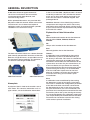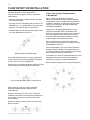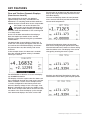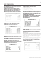
1
M500
ELECTROMAGNETIC FLOWMETER
OPERATION AND
CONFIGURATION MANUAL
IMPORTANT SAFETY INSTRUCTIONS
READ AND FOLLOW ALL INSTRUCTIONS
SAVE THESE INSTRUCTIONS
2
CUSTOMER SERVICE/TECHNICAL SUPPORT/REFERENCE DOCUMENTS
If you have questions about ordering Pentair water flow or water monitoring replacement parts,
please use the following contact information:
Technical Support
Reference Documents
For technical support please quote the following
details which are located on the instrument
enclosure.
Associated documents available for the M500
Electromagnetic Flowmeter include:
Serial Number, example 123456
Part Number, example IR2020
Name and Model: Emflux 500 Series Flowmeter
Power supply, voltage and frequency, if known.
M500 Electromagnetic Flowmeter Operation and
Configuration Manual
M500 Electromagnetic Flowmeter Remote
Communications Guide
M500 Electromagnetic Electromagnetic
Flowmeter File Download Protocol Guide.
© 2014 Pentair Aquatic Eco-Systems, Inc. All rights reserved.
This document is subject to change without notice.
2395 Apopka Blvd., Apopka, FL 32703, USA Phone: 407.886.3939 Web: PentairAES.com
1-21 Monash Dr., Dandenong South, VIC 3175, Australia Phone: 011 61 1 300 137 344
All Pentair trademarks and logos are owned by Pentair or one of its global affiliates. Pentair Aquatic Eco-Systems™,
Pentair Environmental Systems™ and Emluc™ are trademarks of Pentair Aquatic Eco-System, Inc. and/or its
affiliated companies in the United States and/ or other countries. Unless expressly noted, names and brands of
third parties that may be used in this document are not used to indicate an affiliation or endorsement between
the owners of these names and brands and Pentair Aquatic Eco-Systems, Inc. Those names and brands may
be the trademarks or registered trademarks of those third parties. Because we are continuously improving our
products and services, Pentair reserves the right to change specifications without prior notice. Pentair is an equal
opportunity employer.
PAES700-7.A 12/10/14
M500 Operating & Installation Manual
3
TABLE OF CONTENTS
Customer Service/Technical Support..................2
Key Features..........................................................27
Reference Documents...........................................2
Operation.........................................................29
Table Of Contents...................................................3
Power up Display.............................................29
Safety and Usage Precautions..............................4
Flow and Totaliser Channels Displays............31
Introduction.............................................................5
Passcode Entry...............................................32
Principle of Operation.......................................5
Settings and Diagnostic
Information Displays........................................34
Model Numbering and
Optional Accessories........................................6
Configuration...................................................37
Electrical Characteristics..................................8
Configuration Menus.......................................37
Flow Measurement Characteristics.................9
Configuration Sub-menus...............................37
Display and Keypad Characteristics..............10
Parameter Types..............................................38
Digital IO Functional Characteristics.............10
Changing Numeric Parameters......................39
Analog Output Functional Characteristics..... 11
Changing Time Parameters............................42
Ancillary Hardware
Functional Characteristics.............................. 11
Changing Date Parameters.............................44
Diagnostic Functions Characteristics............ 12
On-board Data Logger Functional
Characteristics................................................. 12
Selection and Configuration of
Digital Output Parameters..............................46
Detailed Menu Parameter List........................51
Maintenance..........................................................56
Communications Functional
Characteristics................................................. 12
General.............................................................56
Physical and Environmental
Characteristics................................................. 13
Flow Transmitter..............................................56
Flow Detector...................................................56
Dimensions...................................................... 14
Troubleshooting Guide.........................................57
Quality Assurance and Tracabilit.................... 14
Display is Blank...............................................57
General Description............................................. 17
Display Is Erratic and
Does Not Read Zero........................................57
Nameplate........................................................ 17
Calibration Certificate.....................................18
No Response to Flow......................................57
Electronics Configuration Fingerprint............19
Flow Detector Installation...................................20
Pipe Location and Arrangement.....................20
Electrical Installation of Flow Detector..........23
Signal Cable Connection..........................23
Pipe Not Full (PNF) Cable Connection.....23
Coil Drive Cable Connection....................23
Earthing.....................................................23
Flow Transmitter Installation...........................25
Electrical Installation – M500...................25
Flow Signal................................................26
Coil Connection.........................................26
Pipe Not Full Cable...................................26
M500 Operating & Installation Manual
4
SAFETY AND USAGE PRECAUTIONS
• Read and understand all installation
instructions contained in this Manual.
• If the equipment is used in a manner not
specified by Pentair, the protection provided
by the equipment may be impaired.
• Only suitably qualified personnel may remove
any covers on this product.
• Lethal voltages may be present on conductors,
wiring and on surfaces that are exposed when
a cover is removed from this product.
• Be aware that the coil driver connections
and associated wiring may generate voltages
capable of producing an electric shock.
• Observe the required environmental conditions
and recommended operating conditions for
this product.
• If this product does not operate normally
then refer to the troubleshooting information
contained in this Manual.
• There are no operator serviceable parts inside
this product. Please refer servicing and repair
to qualified service personnel.
• Ensure that the flow transmitter enclosure
is sealed and that the unit is stored in a dry
environment if it is not to be put into service
immediately. The M500 is provided with gland
plugs which enable sealing when cable is
not fitted, also acting as an important safety
measure. Installers must fit provided gland
plugs to any unsealed cable glands. A potential
electrocution risk may exist if any loose object
penetrates an open gland in the base.
• The flow detector may have an insulating lining
that extends to the end of the tube within the
flow detector or over the flange faces. Do not
drag or roll the unit on its end as this may
damage the liner.
• The flow detector must be installed in a position
such that it remains full of liquid at all times
during normal operation.
M500 Operating & Installation Manual
• Cabling between the flow detector and the flow
transmitter should be protected from external
damage and must be routed away from cables
and machines that can generate significant
electromagnetic interference such as variable
frequency drives and electrically operated
machines. The recommended technique is to
install the cable between the flow transmitter
and flow detector within a metallic conduit,
bonded to earth and with suitable physical
protection where the cable enters and exits
the conduit.
• Prior to commencing installation, ensure that the
flow detector and flow transmitter are stamped
with serial numbers that match those listed in
the calibration report. Every M500 Flowmeter
is provided with a calibration report and copies
may be obtained from Pentair Environmental
Systems if required.
• Where fitted, eye bolts should be used to lift the
flow detector. If eye bolts are not fitted, slings
and spreaders should be used. Be aware of the
considerable weight of flowmeter components
and always use safe lifting practices to avoid
personal injury.
• 2060 flow detectors have an insulating liner that
extends over the flange faces. This liner does
not act as a gasket and pipe gaskets must be
fitted during installation.
5
INTRODUCTION
Please note that this symbol is used to
highlight aspects of particular importance
with respect to the operation and safety
of the instrument.
Please ensure that you are conversant
with the operation, installation and
precautions contained within this
manual before installation or operation
of the flow meter.
Principle of Operation
The operating principal of the electromagnetic
flow detector is based on Faraday's law of
magnetic induction that states that the voltage
induced across any conductor as it moves at right
angles through a magnetic field is proportional to
the velocity of that conductor as depicted below:
The signal voltage, Es, between the two electrodes
is proportional to the magnetic flux density (B),
the distance between the electrodes (D) and the
average flow velocity (V) of the fluid.
Es = B x D x V x K
(Equation 1)
Where:
Es = induced electrode voltage
B = magnetic field strength
D = flow detector diameter
V = liquid flow velocity
K = Constant value
The flow transmitter is capable of producing
an accurate and stable current source so that
the magnetic flux density (B) is constant. The
electrode spacing (D) is equal to the flow detector
diameter and is constant due to the construction
of the flow detector. Hence the induced electrode
voltage, Es is proportional to the flow velocity,
V of the fluid.
Equation 1 can also be expressed to show
that the signal voltage Es is proportional to the
volumetric flow rate, Qv:
Qv = π x D2 x V4
(Equation 2)
Es = B x D x K x (Qv / (¶ x D2))0.25
(Equation 3)
The application of Faraday’s law for any magnetic
flowmeter has a number of implications:
Every Pentair flow detector contains windings
(electromagnetic coils) that produce a magnetic
field when a pulsed DC current is applied
from circuitry within the flow transmitter. The
movement of the fluid (i.e. the conductor) through
the pipe and through the magnetic field produces
an electric voltage potential. The voltage is
present within the fluid and is shown as electric
field lines in the above figure. This resulting
voltage, Es, is measured by the flow transmitter
at the measuring electrodes which are directly
exposed to, and in contact with the fluid.
• The resulting voltage Es is not dependent
on the conductivity, but the material flowing
through the pipe must have a certain level
of conductivity for the principle to work. For
water flow applications there is a minimum
level of electrical conductivity (EC) below which
the accuracy of the measurement will suffer.
Pentair flow transmitters routinely check water
conductivity and can produce an alarm if the
conductivity is too low.
• The material in the pipe must cover the
electrodes and in most practical applications
the pipe must be full at all times for accuracy
of measurement. Pentair flowmeters include
a pipe not full detector, which is an additional
connection from the flow detector to the
flow transmitter.
• The Pentair M500 Flowmeter includes electronic
and digital signal processing functions to
provide excellent noise reduction and signal
to noise improvement.
M500 Operating & Installation Manual
6
INTRODUCTION
Model Numbering and Optional Accessories
M500 Specification Code
Details
I500-
Flow transmitter with DC input (12 to 24V).
FW
5
Firmware release version code.
Options
Serial
X
M
R
USB communications only (standard).
Modem port (low power RS232/RS485/RS422) with MODBUS.
Isolated RS485/RS422 port with MODBUS.
Analogue
Outputs
X
M
No analog outputs (standard).
2 x 4-20mA selectable sourcing or sinking & isolation.
Digital IO
X
4D
2 x multifunction outputs (standard).
1 x input, 4 x multifunction outputs.
Options Specification Code
Details
625054
Dual Analog Output Option Card
625055
Isolated RS485/422 Card with Modbus
625056
Modem Interface Card (RS232/RS485/RS422) with Modbus
625057
Digital Expansion Card
Accessories Specification Code
Details
MAGMATE-USB
MagMate Software on USB Memory Stick
CABLE-USB-AB-1
USB connecting cable – 1 meter
M500 Operating & Installation Manual
7
INTRODUCTION
Features
• Programmable alarms and status indication.
• Flow velocity, volume and mass flow
measurement with computation and display
of forward, reverse and net flow.
• Capacitive touch sensitive buttons for long life
mechanical-free operation of keypad.
• Programmable peak and off-peak
flow totalisation.
• Graphic LCD display with LED backlighting for
ease of use and simultaneous display of multiple
flow variables.
• Programmable year to date (YTD)
flow totalisation.
• USB communications interface for ease of
connection in the field to portable computers
with Pentair MagMate software.
• Logged data download via on-board USB port.
• Automatic self-zero and common mode
signal checking.
• Internal digital filtering of input signals with
programmable 50/60 Hz filter response.
• On board data logging with log data storage
to micro-SD card.
• Password protection for setup parameters for
changes made via communications interface
and from front panel interface.
• *Up to four multi-function isolated digital
outputs with selectable operation: alarm/status,
pulse output or frequency output*.
• *Up to two analogue outputs with programmable
selection of output variable and selectable loop
or local powered operation.
• *Isolated multi-function digital input provides
additional control capabilities.
• Simulation mode for quick diagnosis
and training
• Automatic calibration and advanced self
diagnostic functions.
• Integral self test.
• Removable storage media (micro SD card) for
portability of setup configuration, logged data
and diagnostics.
• *MODBUS communications interface with
selection of communications parameters
including RTU or ASCII mode, 2 wire or
4 wire interface.
• Low power operation (I series) with
programmable on and off times for
power management.
• *Modem compatible serial interface for
remote sites.
• Programmable high accuracy current source
with fast settling time.
• Wake command function allows polling by
third-party systems via Modbus interface.
• Worldwide EMC Compliance.
*Note
An option card may be required to
provide feature.
M500 Operating & Installation Manual
8
INTRODUCTION
Electrical Characteristics
Flow Transmitter
Digital Outputs:
Type
Switching Capacity
Rated Contact Voltage
Rated Contact Current
Opto-isolated open collector NPN
3 Watts DC
30 Volts DC
100 milliamps DC
Digital Input:
Operating voltage range
0 to 30 Volts DC
Analog Outputs:
Maximum loop resistance
Nominal circuit voltage
Over range indication
500 Ω
24 Volts DC
22 milliamps DC
Signal Measurement:
Resolution
Linearity
Sampling Rate
Isolation
Input Range
23 bits
±0.001 %
2000 samples per second
Approximately 30 Volts DC.
±13 millivolts DC
Fusing
Internal Fuse Type: T2A.
Ensure power is disconnected before disconnecting or
reconnecting the fuse.
Coil Drive Circuit:
Resolution
Current Output Range
Voltage Range
Switching Frequency Range
Settling Time (typical)1
Coil resistance range
16 bits
100 to 200 milliamps DC
0 to ±36 Volts DC
0.0033 to 16 pulses per second.
Less than 5 milliseconds
25 to 110 Ω
Notes:
1. A
ctual value depends on process conditions.
2. D
ependent on daylight conditions, coil current
and measurement duty cycle.
Flow Detector
Coil Resistance
EM Series
M500 Operating & Installation Manual
Typical value in ohms:
40 ±25
Notice relating to Coil Current:
Maximum reliable coil current for the 500
series transmitter is 200mA
9
INTRODUCTION
Flow Measurement Characteristics
Flow velocity range:
0.01 to 10.00 metres per second
Turndown ratio:
1000:1
Linearity:
<0.005%
Repeatability:
<0.05%
Accuracy:
Better than ±0.5% of flow or ±1mm per second whichever is
greater.
Temperature stability:
<0.05% over temperature range
Noise filtering:
Analog bandpass rejection filter
Digital slope compensation filter
Digital noise reduction filter (50/60 Hz).
Full scale flow rate:
Programmable
Low flow cut-off:
Programmable from 0 to 10% of full scale flow rate. Totalisers are
not updated when flow is below the low cut-off value
Measurement on-time:
Programmable from 3 to 3600 seconds
Measurement off-time:
Programmable from 0 to 3600 seconds
Low flow off-time:
Programmable from 0 to 30000 seconds
Flow channels:
Flow velocity
Volumetric flow rate
Mass flow
Totalised channels:
Total volumetric flow
Total volumetric flow in forward flow direction
Total volumetric flow in reverse flow direction
Total volumetric flow during peak hours
Total volumetric flow in forward direction during peak hours
Total volumetric flow in forward direction during off-peak hours
Year to date total volume
Year to date total volume in forward direction
Year to date total volume in reverse direction
Flow and Totaliser Volume units:
Programmable selection:
• Litres, kilolitres, or mega litres,
• Cubic feet, Acre feet.
• Imperial Gallons, Imperial mega-gallons,
• US Gallons, US mega-gallons,
• User programmable unit conversion factor.
Flow time units:
Programmable selection:
• Seconds, Minutes, Hours, Days,
• User programmable unit conversion factor.
Flow simulation mode 1:
When enabled the user can enter a value for the flow rate,
all outputs and rate calculations are set according to the
simulation value. The coil driver outputs continue to operate.
The totalisers do not update.
Flow simulation mode 2:
Performs same function as mode 1 but with the coil drive output
current fixed at a constant DC value.
M500 Operating & Installation Manual
10
INTRODUCTION
Display and Keypad Characteristics
Graphic LCD Type:
128 x 64 pixel monochrome graphic type with LED backlighting.
Backlight operation:
Can be enabled or disabled, includes auto-off mode when
enabled and after 30 seconds of keypad inactivity.
Keypad:
Four button capacitive touch with adjacent key suppression, self
calibrating, with wake function and press or hold discrimination.
Data update rate:
Approximately 1 Hertz.
Display characters:
Customised character sets (three styles) plus Icons, international
character and language capability.
Password access:
Single level access to detailed data displays and configuration
settings. No password required to view flow rates and totals.
Configuration menu:
Two-level hierarchy: menu and submenu with numerical index to
each menu item for ease of cross referencing.
Meter Identification
Programmable meter code
Digital IO Functional Characteristics
Digital Output Mode:
Digital outputs can be individually programmed for :
• Alarm output (activated by an alarm condition – see below)
• Frequency output (proportional to flow rate channel value)
• Pulse output (one pulse generated for a specified volume)
Alarm Output Mode:
Programmable alarm cause:
• Low battery voltage
• Pipe not full
• System fault
• Low flow
• High flow
• Forward flow detected
• Reverse flow detected
• Analog output 1 over-range
• Analog output 2 over-range
Frequency Output Mode:
• Resolution
• Range
• Duty Cycle
1 Hertz
4 to 1000 Hz
50 %
73Pulse Output Mode:
• Volume per pulse
• Maximum Rate
• Pulse Width
Programmable: 1 to 1000 flow units.
20 Hertz
Programmable 20 to 200 ms
Digital IO Scan Rate
Approximately 1 Hertz
M500 Operating & Installation Manual
11
INTRODUCTION
Analog Output Functional Characteristics
Analog output mode:
Analog outputs can be individually configured for :
• Forward or reverse acting
• Sinking or current sourcing
Output scaling:
0 to 100% of programmed full-scale flow rate
Output update rate:
Approximately 1 Hertz
Ancillary Hardware Functional Characteristics
Power On Self Test
The following tests are performed during power on:
• ADC – Analog to Digital Converter test
• ESN – Electronic Serial Number test
• CRC – CRC Data validation of Configuration data
• DAT – SD Card format and file system verification
• RTC – Real Time Clock test
• PSU – Power supply voltages test
• CIV – Coil Current and Voltage test
Internal temperature monitor.
An internal temperature monitor is used to record the
temperature within the flow transmitter and the temperature
is logged to the SD card.
Internal clock/calendar
High accuracy real time clock circuit with long life battery backup
• 1 second resolution
• Integral calendar functions
• Alarm function, used to schedule internal data logger.
Non-volatile memory
Semiconductor non-volatile memory circuits for storage of:
• Factory calibration data
• Meter calibration and configuration data
• Totaliser values
• Diagnostic information.
• CRC16 checksum validation for all non-volatile data
Electronic Serial Number
A unique electronic serial number is stored in silicon for each
flow transmitter.
Onboard Solar Regulator
Battery voltage, battery current and solar voltage are routinely
monitored. Battery charging is enabled by connection of the
solar panel through a series diode to the battery when solar
voltage exceeds battery voltage by 4.0 volts. The solar panel
is disconnected when battery voltage exceeds 14.8 volts to
prevent overcharging.
M500 Operating & Installation Manual
12
INTRODUCTION
Diagnostic Functions Characteristics
Scan Interval
Programmable: to a multiple (1 to 20) of the data logging interval
Diagnostic Checking
Diagnostic checks are routinely performed to ensure correct
operation of the flow meter. These checks may be used to
generate alarms and may also prevent the totals from being
updated with erroneous values.
• Coil voltage check
• Coil current check
• Electrode check
• Pipe Not Full detection
• Signal voltage check
Additional System checks
• Configuration and calibration data integrity
• A /D Converter operation and self calibration
• Real Time Clock operation
On-board Data Logger Functional Characteristics
Logging interval:
Programmable from 1 minute to 12 hours
Log data storage:
Removable micro-SD card, formatted for FAT (FAT16) allowing
files to be read and copied when the card is inserted into a
personal computer.
File system:
PC Compatible directory structure with individual files for:
• Flow data records (CSV)
• Diagnostic results records (CSV)
• System event records (CSV)
• Alarms records (CSV)
• Configuration data (binary format)
*Comma Separated Volume file, suitable for
import into spreadsheet applications.
Communications Functional Characteristics
USB Protocol
Proprietary packet-based command and file transfer protocol.
Serial Port Command Protocol
Selectable: MODBUS RTU or MODBUS ASCII
Serial Port File Transfer Protocol
Proprietary packet-based command and file transfer protocol.
Serial Port Baud Rate:
Selectable: 9600, 19200 or 38400
Serial Port Line Settings:
No parity, 8 data bits, 1 stop bit (N,8,1).
Supported MODBUS function
codes:
03 – Read Holding Registers
06 – Write Single Register
16 – Write Multiple Registers
M500 Operating & Installation Manual
13
INTRODUCTION
Physical and Environmental Characteristics
M500 Flow Transmitter
Enclosure Construction:
Pressure Die Cast Aluminium
Cable Entries
1xM25 Gland, 1xM20 Gland, 3xM16 Gland.
Weight:
Overall Dimensions:
273H x 115D x 182W
Ambient temperature:
-10 to 55° C
Flow Detector
Housing Construction:
IR2060 - Mild steel with 2 part epoxy coating
IRIR2030 - 304 stainless steel
IR2020 - ABS
Ambient temperature:
-10 to 55° C
Protection Class
IP68 to 5 metres (IR2020 IP68 to 1.5 metres)
Electrodes
316 Stainless Steel (Standard)
Lining:
IR2060 - insulation rubber (Standard)
IR2030 - insulation rubber
IR2020 - ABS
Submergibility:
IR2060 – 10 metres
IR2020 – 1.5 metres
Connecting Cables
Signal Cable
4x16/0.2 BRAIDED SCREEN
Pipe not Full cable
4x16/0.2 BRAIDED SCREEN
Coil Driver Cable
1.5mm TWIN & EARTH ORANGE CIRCULAR
Power Cable
1.0mm Rubberised
M500 Operating & Installation Manual
14
INTRODUCTION
M500 Flow Transmitter
Casing Dimensions
Quality Assurance & Traceability
Quality System Assurance:
This product is manufactured under a quality
system certified as complying with ISO 9001:2008.
Statement of Traceability:
Master Calibration equipment is certified in
accordance with Regulation 13 of the National
Measurement Regulations 1999, Certificate No
34384854801260.
NATA Certification
The Pentair flow meter manufacturing facility has
NATA certification to an accuracy of +/-0.18%
for calibration and testing of flow meters in the
size range 50mm to 200mm diameter. NATA
certification provides independent confirmation of
the accuracy of the manufacturing plant and test
flow facilities and is a further step closer to full
Pattern Approval for the Australian made Pentair
Magnetic Flow Meters.
Note: Drawings not to scale.
M500 Operating & Installation Manual
15
INTRODUCTION
2060 Flow Detector Dimensions
M500 Operating & Installation Manual
16
INTRODUCTION
2020 Flow Detector Dimensions
M500 Operating & Installation Manual
17
GENERAL DESCRIPTION
A 500 Series Electromagnetic flowmeter
consists of an electronic flow transmitter,
an electromagnetic flow detector, and
interconnecting cables.
Mains-powered flowmeters are pre-wired with
AC power cable with internal AC-DC conversion.
The electronic circuit board and optional
equipment cards are mounted inside a powder
coated die-cast aluminium casing.
In the case of the 2020, a duplicate label is inserted
inside the junction box. This will allow the details
of the unit to be traced and/or retrieved in the
event that the label is rendered illegible after
prolonged burial.
2060 flow detectors have identifying numbers
stamped on one flange that allows full factory
information to be retrieved. Simply call the factory
or your nearest Pentair representative and provide
them with this number.
Explanation of label information
Type:
Abbreviated model number for the flow detector.
May be either IR2020, EM2020, IR2060 or
EM2060.
No.:
Unique serial number for the flow detector.
Size:
Nominal pipeline size for the flowmeter.
The flow transmitter mounts on a 50mm diameter
pole normally placed within 10 metres of the flow
detector. Longer distances are possible but must
be specified at time of ordering. The limitation is
a maximum cable length of 100 metres.
2020 Flow Detector
2060 Flow Detector
Nameplate
A polyester label is fixed to the outside case of
each meter. This contains information such as
type number, size and calibration information.
Tubefac:
A calibration factor established by flow testing
the flowmeter system in the flow laboratory at
the factory in Australia. This factor is entered into
configuration parameter of the 500 series flow
transmitter connected to the flow detector for the
system to be accurate. For your convenience, on
a new installation, this parameter has normally
been entered into the flow transmitter prior to the
system leaving the factory. It is recommended
that the calibration report form for the flow
detector and flow transmitter be checked to
ascertain the mating serial numbers prior
to installation.
Zero:
A calibration factor established by flow testing
the flowmeter system at the factory in Australia.
This factor is entered into configuration parameter
of the 500 series flow transmitter connected to
the flow detector for the system to be accurate.
For your convenience, on a new installation, this
parameter has normally been entered into the flow
transmitter prior to the system leaving the factory.
It is recommended that the calibration report form
(see sample below) for the flow detector and flow
transmitter be checked to ascertain the mating
serial numbers prior to installation.
M500 Operating & Installation Manual
18
GENERAL DESCRIPTION
Calibration Certificate
A wet Test Calibration certificate is issued with
every flow meter. It records serial numbers,
configuration settings and calibration parameters
and confirms operational performance accuracy
within specifications.
M500 Operating & Installation Manual
19
GENERAL DESCRIPTION
Electronic Configuration “Fingerprint”
A full electronic record of the full configuration
setting for each transmitter is recorded during the
calibration process. This “electronic fingerprint”
can be used to confirm correct configuration
of the transmitter, and can be ustilised for the
ongoing verification and validation of meter
operational performance.
M500 Operating & Installation Manual
20
FLOW DETECTOR INSTALLATION
Flow Detector Installation
Flow Detector Installation
Precautions
• Do not drag or roll the flow detector on its
end as this may damage the liner or flange
mounting surfaces.
• The flow detector must be installed so that it
remains full of liquid at all times during normal
operation. There are also further requirements
for the arrangement of pipe-work required for
installation as detailed in the following section
“Pipe Location and Arrangement”.
• Be aware of the need to provide proper earthing
bonds and to fit earthing rings to the pipe-work
to ensure proper operation. This is described in
the following section.
• Check the flow detector and flow transmitter
are marked with the correct serial numbers as
given in the calibration report supplied with the
flowmeter. For buried flow detectors, record all
details listed on the flow detector prior to burial.
• Where fitted, eye bolts should be used to lift
the meter. If eye bolts are not fitted, slings and
spreaders should be used.
• 2060 flow detectors have an insulating liner that
extends over the flange faces. The liner does
not act as a gasket. Pipe flange gaskets must
be fitted between the flowmeter lining and the
adjacent pipework.
• Gaskets will also be required for 2020 style flow
detectors when fitted with flanges.
• 2020 flow detectors may be supplied with spigot
connections on one or both ends, which are
intended for installation using Gibault style
connectors or solvent welded to ABS pipe.
If using Gibault connectors prior to installation
check that the outside diameter of the pipework
matches the outside diameter of the 2020 ends
so that the Gibault connector can be properly
fitted (refer Gibault manufacturer’s specification
for maximum allowable variation).
Pipe Location and Arrangement
The following recommendations
are provided as a guide only. It is
common for government authorities
and private institutions to have mandatory
requirements and procedures for installation
of electromagnetic flowmeters.
The following points must be followed to ensure
proper operation of the flowmeter:
• The flow detector may be installed at any angle
but it is extremely important to ensure that
it is completely filled with liquid when a flow
measurement is required.
• Particular care should be taken to ensure that
entrained air cannot accumulate in the flowmeter
or be swept through it from surrounding pipework. This will adversely affect the ability of the
flowmeter to obtain a proper measurement.
• The flowmeter can distinguish between forward
and reverse flows. Each flow detector is fitted
with an arrow indicating the normal forward flow
direction for the installation.
• Electromagnetic flowmeters require that the
fluid is as free from turbulence as possible
within the flow detector. Accordingly it is
necessary to locate the flow detector within
straight sections of pipework. Recommended
practice is to ensure that the sections of straight
pipe are at least five times the internal pipe
diameter from the flow detector.
•F
or flow metering applications where the
flow detector is required to measure both
forward and reverse flow the 5 times rule
should be obeyed for both the upstream and
the downstream pipe sections. For forward
measurement only the length of the downstream
pipe can be reduced to 3 times the pipe
internal diameter.
• Where pipe reducers are used to fit the flow
detector to a pipe with a different diameter,
steep tapers of greater than 8o should be
avoided and the reducers should be located
as far away from the flow detector as possible.
• The flow detector has a removable cover for
access to internal wiring connections. The flow
detector must be located so that the cover is
accessible and easily removed for installation
of cabling and associated conduit.
M500 Operating & Installation Manual
21
FLOW DETECTOR INSTALLATION
• 2020 and 2060 flow detectors are suitable for
direct burial of the flow detector. Be certain
that their location is suitably marked or noted
to avoid damage due to subsequent digging or
trenching operations.
• 2020 and 2060 flow detectors may also
be submerged under water if required
(2060 maximum depth 10 metres,
2020 maximum depth 1.5 metres).
The flow detector may be mounted vertically.
In this case it is essential that the water flow is
in the upwards direction to ensure that the pipe
remains full of liquid.
Mount the flow detector vertically for applications
where the liquid can contain sediment, sand or
other particles. This will help to reduce wear on
the flow detector lining surfaces and electrodes.
The following figures depict the requirements for
flow detector installation.
Mount the flow detector within straight lengths of
pipes to ensure accurate flow measurement.
The length of pipes must provide a minimum
distance between the flow detector electrodes
and pipe bends, pumps, valves or other items
that may cause the water flow to be disturbed.
Locate within Straight Sections of Pipe
Locate within Straight Sections of Pipe
The flow detector must remain completely full of
liquid for accurate flow measurement. In sections
of pipe as shown in this example located the flow
detector in the position as shown. Do not mount
the flow detector in the top (horizontal) or in the
vertical section where flow is downwards.
The lengths of straight pipe sections must be:
• A minimum of 5 times the flow detector diameter
from the electrodes for the pipe feeding the flow
detector (ie upstream).
• A minimum of 5 times the flow detector diameter
for the downstream pipe for reverse flow
measurement applications.
• A minimum of 3 times the flow detector diameter
for the downstream pipe where the application
does not involve reverse flow measurement.
Ensure the Pipe Remains Completely
Full of Liquid
M500 Operating & Installation Manual
22
FLOW DETECTOR INSTALLATION
The flow detector can be fitted within
inclined sections of pipes, with the conditions
noted above:
• Must be fitted within straight sections of pipes
of minimum lengths.
• The pipe must be completely full of water at the
flow detector – it is preferable to locate the flow
detector at the lowest point in the incline.
• The flow detector must be mounted with a tilt of
less than 20 degrees to vertical.
Other Pipe Layout Requirements
& Standards
Note – There may be State or National
Metering Standards that may impose different
requirements on the straight pipe requirements.
Guidance should be sought from relevant state
agency or by reference to National Metering
Installation Guidelines.
Flange faces of adjoining pipework must be
aligned and parallel within reasonable limits.
Excessive misalignment could result in leakage
from the flange or place undue stress on the
structure of the flow tube, resulting in internal
water leakage and failure of the meter.
Design allowance for structural slippage in
pipe-supporting framework can reduce severity
of longitudinal stresses.
Mounting within Inclined Pipes
Fit the flow detector within a section of pipe that
is lower than the surrounding pipework for pipes
that are known to run partially filled.
Caution: this may lead to problems where the pipe
carries liquids containing particulate matter.
Use a U Section When Pipe is Partially Full
Flow metering accuracy can be improved
by fitting the flow detector between flow
area reducers.
Caution: The reducers will cause unwanted
turbulence and affect measurement performance
if the angle of the tube is greater than 8O to
the horizontal.
Caution: Installing reducers will cause pressure
drop in the line.
M500 Operating & Installation Manual
These longitudinal stresses are often imparted
through thermal variation in the pipework and /
or ‘pulling together’ of the pipework by the flange
bolts, during installation of the meter.
Installation of a meter in fixed pipework can cause
damage to the meter if there is not sufficient
slippage or capacity to accommodate gaps.
Bolts should be tightened in an opposite pattern.
23
FLOW DETECTOR INSTALLATION
Electrical Installation of Flow Detector
The electrical wiring and connections at the flow
detector include:
• Electrodes – there are three electrode
connections, two measurement electrodes
and one pipe not full detection electrode.
• Coils – two connections are provided to drive
the coils that produce the magnetic field within
the flow detector.
• Earthing - for correct operation it is essential for
the flo wing liquid to be earthed at both ends of
the flow detector. Recommended earthing also
includes connection to an earth stake located
near the flow detector.
The connections between the Flow Detector
and the Flow Transmitter usually require three
individual cables: a signal cable and cables for
the coil drive and pipe not full signal.
• Signal ground – depending on the model of
flow detector, there are two or three connection
points for ground reference between the flow
detector and flow transmitter.
Signal Cable Connection
For proper operation and to enable full specified
accuracy of the flowmeter the following signal
connections must be made at the flow detector.
The connection arrangements for two styles of
cables are shown in the diagram below:
Communications Functional Characteristics
Connection
Signal
Notes
Electrode (+)
Flow voltage positive
Electrode (-)
Flow voltage negative
Proper operation requires these
millivolt signals to be as noise-free
as possible.
Guard (+)
Signal guard driver positive
Guard (-)
Signal guard driver negative
Inner Shield
Cable shield wire (drain wire)
Ground connection between Flow
Detector and Flow Transmitter
Outer Shield
Overall cable shield
Connect to earth bond at Flow
Detector
Do not connect at Flow Detector
Pipe Not Full (PNF) Cable Connection
For flow detectors with a PNF electrode the
following signal connections must be made at
the flow detector.
Communications Functional Characteristics
Connection
Signal
Notes
PNF Electrode
Pipe not full
Proper operation requires this
millivolt signal to be as noise-free
as possible.
Outer Shield
Overall cable shield
Connect to earth bond at Flow
Detector
M500 Operating & Installation Manual
24
FLOW DETECTOR INSTALLATION
Coil Drive Cable Connection
Connection
Signal
Notes
Outer Shield
Overall cable shield
Connect to earth bond at Flow
Detector
Coil A
Coil drive A
Coil B
Coil drive B
Provides coil drive to Flow
Detector.
Earthing
For correct operation it is essential for the
flowing liquid to be earthed at both ends of the
flow detector. If the adjacent pipework does not
contain an electrically insulating lining and is
in good electrical contact with the liquid then
the adjacent pipes can be used for the earth
connection.
If adjacent pipework is not electrically conducting
or is lined with an electrically insulating material,
then earth rings or earth electrodes must be used.
These earth rings must be strapped to the flow
detector flanges at both ends of the flow detector.
Earth rings must be installed with a gasket
either side.
Earth straps should be connected between the
pipework flanges and the flowmeter flanges
particularly when flexible self sealing couplings
are used. Flange bolts do not always provide
good electrical earth connections between
metallic flanges.
Some flow detectors have an internal
lining that extends over the flange faces.
The lining material does NOT form a
gasket. When installing the flow detector, gaskets
must be provided between the flowmeter lining
and the adjacent pipe flanges.
2020 Flow detectors have a reference
electrode eliminating the requirement for
earth rings in non conductive pipes.
M500 Operating & Installation Manual
25
FLOW DETECTOR INSTALLATION
Flow Transmitter Installation
Flow Transmitter Installation Precautions
• Observe the recommended operating conditions
for the flow transmitter (refer to Specifications),
including the specified maximum cable distance
between the flow detector and flow transmitter.
• Do not position the transmitter so that it is
difficult to operate the electrical disconnect
device. Ensure that the power switch is
accessible to personnel.
• Cables between the flow detector and flow
transmitter should be run in metal conduit for
mechanical protection and noise minimisation.
Recommended practice is to earth the conduit
which should be run up the inside of the flow
transmitter mounting post.
•F
low transmitters should be located in a
shaded position to minimise heating and effects
of sunlight.
• Position the transmitter at a height that provides
convenience of reading the display and
operating the keypad.
• Separate conduits are needed for coil supply,
signal and accessories. Refer to Part C Mechanical Installation of Flow transmitter for
details.
• Ensure the electrical power supply for the M500
is adequately earthed.
Electrical Installation – M500
Electrical installation should be carried out by
suitably qualified personnel and should conform
to local codes and wiring practices.
To access the electrical connections open the
box with allen keys. Do not attempt to connect
or disconnect the AC wiring.
M500 Operating & Installation Manual
26
FLOW DETECTOR INSTALLATION
Flow Signal
The flow signal is received via the shielded 4 core
black cable. The cable should be located against
the inside of the box down to the terminal strip.
It needs to be long enough to enable the battery
to sit in the bottom of the enclosure and for the
door to be opened without applying tension on
the cable.
Electrical connections should be carried
out following best practices outlined in
the Australian Standards for Wiring AS/
NZS 3000:2007.
Coil Connection
The coils are connected using the orange
sheathed cable with red, black and green cores.
Pipe Not Full Cable
Where required a second black cable is fitted, the
yellow conductor connects to PNF input and the
shield is connected to PNF Shield.
External Aerial Cable
Where fitted, an external aerial cable can be
inserted through an M16 gland.
M500 Operating & Installation Manual
27
KEY FEATURES
Low Power Mode Operation
Off time
The M500 Flowmeter is designed for low power
operation at remote sites. A power saving
mode is available whereby the unit remains
in a sleep (low power) mode and only wakes
up and performs a measurement (high power)
mode at user predefined intervals. Typically
the units are configured to wake up every 3-5
minutes and remain awake for 30 seconds.
During the shutdown or sleep period, the flow
totalisers continue to accumulate in real time,
and all outputs such as pulse, frequency and
current outputs continue to operate. Serial
communications are available at any time.
If two successive zero flow detections occur,
the system shuts down for a configurable
extended off period. (Refer to the section
below - Configuration).
The off time determines how long a period the
device will enter into a low power state between
corresponding scan intervals. Increasing the Off
time decreases power consumption, while on the
other hand, decreasing the Off time will provide
more flow readings on a more regular basis.
To read the meter while in the power saving mode
it is simply a matter of pushing the tick button.
This will wake the system up to initiate a new flow
measuring cycle and to update the display with
the new flow rate. This feature can also be used
when setting or adjusting the flow rate.
The LCD and backlight have programmable
off-times: pressing a key will wake the LCD
which has an auto-off feature.
On time
The On time determines how long the system is
active for. The On time includes:
• Time to power up flow metering circuits
• Time to perform flow readings
Critically, the On time must be long enough to
allow the device to generate a new flow reading.
Without allowing for this, the flow rate would
never be updated. To ensure this does not occur,
the firmware automatically extends the On time,
if the user has selected a value that is too short
to generate a new flow reading at the current coil
frequency or response time setting.
Shorter on times will typically reduce power
consumption (only if the off time is > 0), while
longer on times will allow more flow readings
to be performed in quick concession.
Flow Measurement Process
• The unit wakes from Sleep mode after the user
defined Off Time.
• The unit powers up the flow meter circuit and
performs digital filtering to generate clean flow
readings. After the fixed warm up period the
LCD screen will update with flow reading.
• Smoothing (running average of between 1-100
points) is then applied to the flow readings.
• Unit will remain awake for the remainder of the
Wake (On Time) with live flow updates
• After the Wake time the unit then returns to
sleep mode.
• During sleep mode all outputs remain at their
current values until the next wake up.
• All other data (Date, time, flow totals) continue to
update in real time during the sleep mode.
No Flow Condition
When the flow rate falls below a specified value
“Zero Flow Cut Off” the transmitter forces the
flow rate to zero and a ‘LOW FLOW’ message
appears on the LCD screen.
Pipe Not Full Condition
The flowmeter includes a 'Pipe Not Full'
function which can be enabled or disabled in
the configuration. The transmitter utilises an
electrode located at the top of the pipe. If there
is no water covering the electrode then the
transmitter will show a 'PIPE NOT FULL' message.
If a “Pipe Not Full” conditions is detected – flow
rate is forced to zero flow.
M500 Operating & Installation Manual
28
KEY FEATURES
Digital Outputs
Modular Electronics
There are two standard plus two optional digital
outputs which are opto-isolated open collector
NPN outputs. These outputs can be configured to
operate in the following modes:
• Frequency output: the frequency is proportional
to the selected flow channel which may be flow
rate, velocity or mass flow. The range of output
frequency can be programmed in the range
0 to 1000 Hz. Frequency output will continue
during power save mode. The frequency outputs
allow retransmission of flow rate variables to an
external system.
The 500 Series flow transmitter is designed to
operate with a wide range of flow detectors (from
50mm up to 1000mm diameter) and has flexibility
to be able to be swapped to operate on different
flow detectors. Several user configuration
parameters (Flow Tube Factor and Flow tube zero)
are able to be changed to allow the transmitter
to operate on different flow tubes. This feature
allows a small number of spare electronics
packages (doors) to be held for swapping into
remote sites as required.
• Pulse output: pulses are generated in proportion
to the occurrence of a specified volume of flow
volume. For example the system may generate
one pulse for every 10 litres. The duration of the
pulse and the totaliser channel that causes the
pulse can be selected. Pulse outputs continue
during the power save mode. Pulse outputs are
typically used to interface with remote counters,
telemetry systems and watering systems.
• Alarm Indication: the output can be used
to indicate an alarm condition, such as a
fault condition. The alarm cause is able to
be configured.
Dual Totalisers (Peak and Off Peak Flow
Totals)
The 500 series includes two independent flow
totaliser channels (Dual totalisers) to keep track
of flow volumes that may be delivered during
certain times of the day. This function is typically
used to keep track of Pumped Flows delivered
during Off Peak Electricity Tariffs, and flow
volumes delivered during Peak Electricity Tariffs.
The user can enter the start and stop times for the
Off Peak Period (which usually coincides with low
electricity demand – for example
23:00 – 07.00AM).
M500 Operating & Installation Manual
Signal Measurement & Processing
The unit wakes up to take measurements and
provide various signal processing and digital
filtering routines to deliver a highly accurate and
repeatable flow signal. The outputs from the
flow meter update only after a smooth clean flow
reading is available. The user can configure the
unit to best meet the measurement requirements
and wide range of site conditions.
Electrode Check (EC measuring) &
Signal Check (within range)
The I500 diagnostics checks the functionality of
the electrodes and the presence of known faults
in the signal which could be caused by an issue
such as a short circuit inside the detector head or
a fault in the cable.
29
KEY FEATURES
Operation
The M500 Electromagnetic Flowmeter local
interface consists of a graphic LCD display with
4 button capacitive touch keypad.
Pressing the tick key will wake up the unit and
activate the display. If the unit is in sleep mode
then pressing a key will cause flow metering to
recommence.
The local interface provides six main functions:
• Power up Display (self-test status and firmware
version indication).
• Display of flow variables and alarms.
• Passcode entry.
• Read only display of settings and
diagnostic information.
• Configuration of user settings
(configuration menus).
• Calibration settings menu.
Power up Display
When first powered up, the flow transmitter
performs a series of self-checks and auto
calibration. The Firmware Version is displayed on
the top line.
Code
Self Check Result if Pass
ADC
Digital operation of the 24 bit sampling Analog to Digital Converter is correct
ESN
The electronic serial identification number is valid: the serial number is displayed
CRC
The basic calibration data in EEPROM is valid
DAT
The file system on the SD Card is valid
RTC
Digital operation of the Real Time Clock is correct
PSU
A voltage within the correct range is present on either the battery or solar inputs
CIV
The flow detector coils are within the correct voltage and current range
M500 Operating & Installation Manual
30
KEY FEATURES
Password Access – LCD SCreen
The M500 is designed to meet new Australian
standards for Non Urban Metering and provides
several levels of password access and protection
as follows:
Access
Level
User Type
Functions
Password
User
Landholder /
Operator
Read Flow Data
No Password
required
Push Any Button to scroll
through display screens
Low
Water Baliff / CSO Read Configuration &
Diagnostic Settings
Level 0
Hold Tick Key 2s
Enter Level 0 code
Med
Asset Owner /
Meter Technician
Read all configuration
and diagnostic settings,
Limited Write capability
Level 1
Hold Tick Key 2s
Enter Level 1 code
High
Asset Owner /
Meter Technician
Full Read and Write
Configuration Settings
Level 2
Hold Tick Key 2s
Enter Level 2 code
Password Access – MagMate Software
The Mag Mate software prompts the user to
enter a password to perform various changes
as follows:
Access
Level
User Type
Functions
Password
Low
Water Service
Officer
Connect to View and
collect diagnostic & flow
No Password
Med
Meter Technician
Read Configuration &
Diagnostic & modify
configuration Settings
Level 1
High
Asset Owner /
Factory trained
& cerified Meter
Technician
Full Read and Write
access to all available
Configuration Settings
Level 2
Note:
LCD Passwords can be changed by the user.
(User is permitted to change current level
password or lower level passwords)
Magmate Passwords are hard coded into
the I500.
If Passwords are lost or forgotten:
Please contact your Pentair service
team for assistance.
M500 Operating & Installation Manual
31
KEY FEATURES
Flow and Totaliser Channels Displays
(User Access Level 0)
Pressing the up or down key will select the next
display. Pressing the back key will return to the
Flow Rate display.
Flow and totaliser channels are updated
approximately once every second when the
flowmeter is in sampling mode and the totalisers
update once per second when also in sleep mode.
The nett total display shows the nett (forward
minus reverse flow total) and the forward and
reverse total components.
If the LCD is not active this does not
necessarily mean that the flowmeter is in
low power mode. Similarly, the LCD may
be active when the flowmeter is not scanning and
is in sleep mode.
Access to the flow and totaliser data displays
does not require passcode access and the
displays can be selected using the up and down
arrow buttons.
The default flow channel display “Flow Rate” is
shown left. This display will appear after the self
test and version information display and shows
the present flow rate, flow velocity and status
of alarms.
In the example shown, the flow rate is 4.16832
litres per second, the flow velocity is 2.12295
metres per second.
The STATUS Bar at bottom of screen will display
any ALARM information
The Peak Total display shows the totalised
flow values during the peak period for the day.
The forward and reverse totals are shown along
with the volume units. The display units can be
changed by entering the menu system.
Similarly, the Off-Peak Total display shows the
totalised flow values during the off-peak period.
The display of alarms requires that the alarms are
first configured, through the setup menus and the
alarm condition is active. As an example, alarm
1 can be configured for low battery alarm and
when the battery voltage is low a message “Low
Battery” will appear next to the text “ALM” on the
LCD. There are 4 possible alarms and if more than
one alarm exists then the display cycles through
each alarm and displays the status on the LCD.
M500 Operating & Installation Manual
32
KEY FEATURES
The Year To Date (YTD) Total screen shows the
nett (forward less reverse) totalised flow value on
the first line. The second and third lines show the
forward and reverse flow values.
Passcode Entry
Passcodes are used by the 500 series flow
transmitter to provide multi-level access to data
displays. The passcode access automatically
expires one minute after the user exits back to the
channel data displays. Until the passcode expires,
the user retains access to the user settings and
further information pages without having to reenter the passcode. Once the passcode expires,
the user is prompted to enter a password prior
to gaining access to restricted areas.
There are 3 levels of passcode protection,
described below.
Thre are two power inputs to the flowmeter:
a battery input and an optional input from a
solar panel. The voltages for each are displayed
on the Battery Voltage display.
Level
Access
0
Correct passcode allows full read, no
write.
1
Correct passcode allows full read,
limited write
2
Correct passcode allows full read and
full write.
Access level 0 requires a valid passcode and
allows the user to view all information but not
make changes.
The Reset/Uptime screen provides diagnostic
information. It shows the number of power on
resets. And the uptime since the last reset in
days and hours.
Access level 1 requires a valid passcode to be
entered and allows the user to view all information
and make changes to the configuration (setup)
settings. Write access is limited to configuration
setup parameters: calibration settings are
read-only.
Access level 2 provides full read and write access
including calibration settings.
If a user enters a level one passcode, the
passcode must be allowed to expire before
entering a level two passcode.
The method to enter a passcode is shown below.
To access the Passcode entry page, hold the
‘tick’ button when viewing any of the channel
data displays pages from the Data Channel series
of pages.
The flow totaliser units (kilolitres, in the above
example) can be changed in the configuration
menus. This is discussed in detail in a following
section. The latch date (start of the year) and peak
and off-peak times (hours of day) can also be
configured using the menu.
M500 Operating & Installation Manual
33
KEY FEATURES
After holding the ‘Tick’ button for 2 seconds, the
user is prompted with the passcode entry page.
The cursor can be moved left and right using the
up and down buttons.
Pressing ‘Tick’ selects a digit. The inverted digit
indicates that it can now be changed.
Pressing ‘Tick’ accepts the change.
The access code is not validated until the user
presses the Back button.
In this example, ‘0123’ is a valid level 2 passcode.
Repeating the above steps with an invalid
passcode results in denied access.
After displaying the screen for approximately
1 second, a failed passcode attempt returns
to the previous Data Channels display.
Pressing ‘Up’ or ‘Down’ increments or
decrements the digit.
M500 Operating & Installation Manual
34
KEY FEATURES
Settings and Diagnostic Information
Displays (User Access Level 1 or 2)
The settings and diagnostic information displays
can be viewed only with access level 1 or 2
and by a momentary press of the tick key.
The information is shown in summary format so
that it can be concisely displayed. A description
of the information displayed is presented below.
SITE ID: an assignable number and is
independent of the Modbus address.
METER ID: an assignable number and is
independent of the Modbus address.
SERIAL NUMBER: each flow transmitter has
a unique electronic serial number in a 12 digit
hexadecimal format, as shown. Refer this number
in any warranty or technical support enquiries.
BATTERY VOLTS: Battery Voltage at the
power connector.
SOL VOLTS: Solar Voltage at the power connector.
This voltage may show a non-zero reading when
the solar panel is not connected. This is normal
and does not indicate any fault in the electronics.
BATTERY AMPS: Battery Current during
solar charging.
TEMPRATURE: temperature within the flow
transmitter enclosure [°C]. This may differ from
outside air temperature.
SIGNAL IN: Signal Input Voltage. The voltage of
the flow signal from the flow detector in millivolts.
DATE/TIME: current date and time.
CARD SLOT 1 – 3: shows the currently installed
option cards.
The current date and time shown in the format
dd/mm/yy hh:mm:ss.
The example shows the time is 38 seconds past
3:16pm on the 15th of June 2009.
FACTORY CALIBRATED: date and time the unit
was calibrated in the factory.
LAST FIELD CALIBRATED: date and time the unit
was last calibrated in the field using the Pentair
infield verification tool.
The 500 series flow transmitter has 4 alarms that
can be configured to generate a digital output
and/or for alarm event logging. The Alarm Status
display shows the configuration of the 4 alarms at
the left, and the status of each alarm at the right.
M500 Operating & Installation Manual
35
KEY FEATURES
COIL CURRENT is the coil current setting in mA
(not the measured current).
SIMULATE MODE: Simulation Mode,
TUBE SET 0 to 2: the threshold flow voltage
defined in mV. If the unit is calibrated for multitube factor operation, this setting allows the
device to utilise settings specifically calibrated
for low flow operation.
1. Flow signal simulation
0. Normal operation
2. Coil DC output simulation.
FAILSAFE LOW: determines whether the flow rate
outputs assume zero or full scale on a signal fault.
PNF DETECTOR: the pipe not full detector status:
enabled (ON) or disabled (OFF).
PNF THRESHLD: a set point for the PNF detector.
EC THRESHLD: a set point for the Electrode
Checking detector.
TUBE FCTR 1-4: the calibrated tube factors.
TUBE ZERO: the calibrated tube zero.
SIMUL. VAL: value that is set when the simulation
mode is enabled.
FULL SCALE: flow rate full scale - used for the
high flow rate alarm set-point, expressed in the
flow rate units.
DENSITY: the relationship between flow rate and
mass flow rate.
COIL FREQ.: the coil output switching frequency
to drive the coils in the tube.
PIPE DIA.: the diameter of the pipe in mm.
LOW CUTOFF: Low flow rate cut-off, expressed as
a velocity in mm/sec. The percentage of full scale
below which flow is considered to be negligible
and therefore 0.
ZERO CUTOFF: Low flow rate cut-off, expressed
as a velocity in mm/sec. The percentage of
full scale below which flow is considered to be
negligible and therefore 0.
MAINS FREQ.: the frequency of the rejection filter
used for the input signal processing.
M500 Operating & Installation Manual
36
KEY FEATURES
VOLUM. FCTR, TIME FCTR, TOTALS FCTR:
scaling factors can be applied to the volume,
time and totaliser units instead of standard units:
these are the scaling factors.
TYPE: selectable from frequency output,
pulse output, alarm output or disable.
MAX FREQ: the maximum output frequency when
in frequency mode. This value correlates to the
full scale flow rate.
CHANNEL: the channel that causes the pulse or
frequency output.
PULSE SCALE: the value of each pulse output
in Litres. The example shows that each pulse
represents 1L of flow.
PULSE WIDTH: the width of the pulse in ms.
The example shows that each pulse has a width
of 20ms.
OFF PEAK START: Off peak period start time in
24 hour format.
STATUS: shows the current status of the output
(ON or OFF).
OFF PEAK STOP: Off peak stop time in
24 hour format
END OF YEAR LATCH: end of year latch date.
The date at which the YTD totals are all reset
to 0. It is in the format hh:mm:ss dd-MMM The
example shows that the latch date occurs at the
very beginning of the new year (1st January at
00:00:00).
ACTION: selectable from forward (0% = 4mA,
100% = 20 mA), reverse (0% = 20 mA, 100% =
4mA), bidirectional (0% = 12mA, 100% = 20 mA,
-100% = 4 mA).
CHANNEL: selectable from flow rate, flow velocity
or mass flow.
DAMPING: a signal smoothing factor.
ZERO TRIM: the flow value at which the output
is 0%.
Alarm settings show the alarm cause, for example
low battery, low flow, high flow, pipe not full,
system fault, forward flow, reverse flow.
LOG ALARM: if ON the alarm is logged to the SD
card when the alarm condition changes from false
to true.
M500 Operating & Installation Manual
SPAN TRIM: the flow value at which the output
is 100%.
37
KEY FEATURES
MODE: selectable RS232 or RS485/422.
ADDRESS: Modbus address 0..247
BAUD RATE: selectable 9600, 19200, 38400.
SETTINGS: selectable N,8,1 or N,7,1.
Configuration (User Access Level 2)
It is highly recommended that all
configuration settings be checked
and documented to ensure the unit
is configured to suit the particular site
requirements and to provide a history of the
site configuration settings.
Configuration Menus
The configuration menu is accessed by entering
a valid Level 2 passcode.
Back button – return to previous display.
Up and down buttons - move selection.
COIL VOLTS: The steady-state coil voltage when
current is applied.
Tick button – select menu option.
COIL CURRENT: the steady state measured coil
current setting in Amps.
COIL OHMS, Coil resistance. The measured
resistance of the coils.
This display shows the status of the diagnostic
checks that are regularly performed by the
flow transmitter.
Configuration Sub-menus
Each menu selection has a submenu that allows
parameters to be selected to change settings.
Back button – returns to configuration menu.
Up and down buttons - move selection.
Tick button – select submenu option.
M500 Operating & Installation Manual
38
KEY FEATURES
Parameter Types
There are four main parameter types as
outlined below.
Type
Example Display
Option
Description
Option selection
The user is able to select from a list of
options/choices using the up and down
buttons. Pressing the back key selects that
option. The option when selected is saved
to the non-volatile settings memory.
Numeric
Numeric entry
The user is able to change the number to
any number within a valid range. The current
value is displayed for reference.
The method for changing settings with a
number field is shown in a following section.
Time
Time entry
The user is able to change the time field
within the specified HH:MM:SS format. Note
that the time is 24 hour format.
Date
Date entry
The user is able to change the date field
within the specified DD/MM/YY format.
M500 Operating & Installation Manual
39
KEY FEATURES
Changing Numeric Parameters
Screen
Action
The screen shows the number from the field matching
that of the current value. The cursor is currently
underneath the ‘+’ symbol. The next image shows the
effect of pressing ‘Tick’.
Pressing ‘Tick’ when the cursor is beneath the sign (‘+’
or ‘-‘), allows the symbol to be modified. The picture
shows an inverted ‘+’ symbol, indicating it can be
changed as per the next image in the series.
Pressing ‘Up’ or ‘Down causes the sign of the number
to change. The number is now a negative number.
Pressing Tick accepts the change, returning the cursor
to the digit select format. Pressing ‘Up’ or ‘Down’ now
moves the cursor to the left and right respectively.
Pressing ‘Down’ causes the cursor to move to the right
and underneath the most significant digit.
M500 Operating & Installation Manual
40
KEY FEATURES
Changing Numeric Parameters
Screen
Action
Pressing ‘Down’ causes the cursor to move beneath the
decimal symbol.
Pressing ‘Tick’ selects the decimal point, placing an
arrow beneath it and allowing it to be moved left or
right. Note: The pictured example, will not allow the
decimal point to move further left. Nor can the decimal
point move further right than the last digit.
Pressing ‘Down’ moves the decimal point 1 digit to
the right.
Pressing ‘Tick’ accepts the new location of the decimal
point and returns the cursor to the digit select mode.
Pressing ‘Down’ moves the cursor to the right.
M500 Operating & Installation Manual
41
KEY FEATURES
Changing Numeric Parameters
Screen
Action
Pressing ‘Tick’ selects the digit and allows it to be
modified. Pressing ‘Up’ and ‘Down’ in the selected state
increment or decrements the digit respectively.
Pressing ‘Down’ decrements the digit causing the
number to wrap back around to ‘9’. Note: Pressing
‘Back’ when a digit is selected causes the digit to return
to the previous value and the cursor to its original state
as a digit select cursor.
Pressing ‘Tick’ accepts the new value for the digit.
Pressing ‘Back’ prompts the user whether they wish
to save the modified number to the current setting.
Pressing ‘Tick’ when “NO” is selected causes the
device to return to the previous menu without saving
the modified number. Pressing ‘Up’ or ‘Down’ moves
the selected option as shown in the next image in the
series.
Pressing ‘Tick’ when “YES” is selected from the save
change prompt causes the device to return the screen
to the previous menu and saves the new setting causing
it to take effect.
M500 Operating & Installation Manual
42
KEY FEATURES
Changing Time Parameters
Screen
Action
The time field allows the user to change any of the
digits individually. Pressing ‘Up’ or ‘Down’ moves the
cursor left or right respectively.
Pressing ‘Down’ moves the cursor to the next digit on
the right.
Pressing ‘Down’ moves the cursor to the next digit on
the right.
Pressing ‘Down’ moves the cursor to the next digit on
the right.
Pressing ‘Tick’ allows the selected digit to be modified
by pressing ‘Up’ or ‘Down’.
M500 Operating & Installation Manual
43
KEY FEATURES
Changing Time Parameters
Screen
Action
Pressing ‘Down’, decreases the value of the selected
digit by 1. Pressing ‘Back’ returns the digit to the
previous value, pressing ‘Tick’ changes the digit to the
new value while both keys cause the cursor to return to
the digit select cursor type.
The user has pressed ‘Tick’ accepting the new value
and returning the cursor to the digit select type.
Pressing ‘Back’ prompts the user if they wish to save
the new value. Pressing ‘Back’ removes the save
change prompt. Pressing ‘Up’ or ‘Down’ changes the
response to “YES” or “NO”. Responding with “NO”
results in the device returning to the previous setting
menu without making changes to the time setting.
Selecting “YES” returns the unit to the previous setting
menu saving the new time setting.y
M500 Operating & Installation Manual
44
KEY FEATURES
Changing Date Parameters
Screen
Action
The date field allows the user to change any of the
digits individually. Pressing ‘Up’ or ‘Down’ moves the
cursor left or right respectively.
Pressing ‘Down’ moves the cursor to the next digit on
the right.
Pressing ‘Tick’ allows the selected digit to be modified
by pressing ‘Up’ or ‘Down’.
Pressing ‘Down’, decreases the value of the selected
digit by 1. Pressing ‘Back’ returns the digit to the
previous value, pressing ‘Tick’ changes the digit to the
new value while both keys cause the cursor to return to
the digit select cursor type.
Pressing ‘Tick’ the user has changed the date from the
15th to the 14th.
M500 Operating & Installation Manual
45
KEY FEATURES
Changing Date Parameters
Screen
Action
Pressing ‘Back’ prompts the user if they wish to save
the new value. Pressing ‘Back’ removes the save
change prompt. Pressing ‘Up’ or ‘Down’ changes the
response to “YES” or “NO”. Responding with “NO”
results in the device returning to the previous setting
menu without making changes to the date setting.
Selecting “YES” returns the unit to the previous setting
menu saving the new date setting.
When YES is selected from the Save
Changes prompt, it may take up to
30 seconds until the change is stored
within non-volatile memory.
M500 Operating & Installation Manual
46
KEY FEATURES
Selection and Configuration of Digital Output Parameters
Screen
Action
After holding the ‘Tick’ button for 2 seconds, the user
is prompted with the passcode entry page.
Enter Level 1 / Level 2 access code.
Select ‘7. DIGITAL OUT MENU’. Using the up and down
arrows, and pressing TICK.
Select mode for channel 1 using ‘DIGITAL OUT MODE’
(item 7.1). The choices include Off, Frequency,
Pulse and Alarm.
M500 Operating & Installation Manual
47
KEY FEATURES
Selection and configuration of ‘frequency output’ method
Screen
Action
Select ‘FREQUENCY’ from menu item 7.1 using the up
and down arrows, and press TICK.
Press ‘back’ to go back to the DIGITAL OUTPUTS menu.
Select ‘FREQUENCY MAX 1’ from the digital outputs
menu. Press TICK.
For frequency Max 1: Select frequency max (menu
item 7.2) choosing a value between 0 and 1000. Values
can be chosen by: (1) pressing the up and down
arrows to select the number, (2) pressing TICK to
modify the number, and (3) pressing the up and down
arrows to change the number. Press ‘BACK’ to exit the
FREQUENCY MAX 1 selection.
Select ‘7.3 INPUT CHANNEL 1’ from the digital
outputs menu.
From Input channel 1, select the parameter for
monitoring from the list of ‘velocity’, ‘flow rate’,
‘mass flow’, ‘fwd total’, ‘rev total’, and ‘nett total’.
M500 Operating & Installation Manual
48
KEY FEATURES
Selection and configuration of ‘pulse output’ method
Screen
Action
Select ‘PULSE’ from menu item 7.1.
Select input channel 1 (option 7.3).
From Input channel 1, select the parameter for
monitoring from the list of ‘velocity’, ‘flow rate’,
‘mass flow’, ‘fwd total’, ‘rev total’, and ‘nett total’.
Select ‘PULSE SCALE’. (item 7.4)
M500 Operating & Installation Manual
49
KEY FEATURES
Selection and configuration of ‘frequency output’ method
Screen
Action
Note: there is a factor of x10 in the pulse scale output.
i.e. 0100 equates to 10L.
Values can be chosen by: (1) pressing the up and down
arrows to select the number, (2) pressing TICK to
modify the number, and (3) pressing the up and down
arrows to change the number. Press ‘BACK’ to exit the
PULSE SCALE 1 selection.
Select item 7.5 ‘PULSE WIDTH’.
Set the pulse width (default value is 020), by following
the same procedure as followed when setting the
pulse scale.
Notes:
•T
he pulse train out of the Digital Output is
nonlinear (different to the I300 and M300 where
the pulse train out of the DO is linear).
• Missed pulses (where the maximum frequency
pulse output has been exceeded) will be ‘caught
up’. I.e. the I500 will generate additional pulses
in order to catch up on the pulses which have
been missed.
M500 Operating & Installation Manual
50
KEY FEATURES
Selection and configuration of ‘alarm’ method
Screen
Action
Select ‘alarm’ from menu item 7.1.
Go back to the main ‘meter menus’ screen by pressing
the back button. Select ‘6. Alarms menu’.
Select item 6.1 ‘ALARM CAUSE 1’.
From ALARM CAUSE 1, select the alarm cause from the
list: ‘low battery’, ‘pipe not full’, ‘system fault’, ‘lo flow’,
‘hi flow’, and ‘forward flow.
From menu 6.2 LOG ALARM 1:
Select ‘OFF’ or ‘ON’.
Repeat process for alarms 2 to 4.
M500 Operating & Installation Manual
51
KEY FEATURES
Detailed Menu Parameter List
Parameters are shown below in the order that
they appear in the menu and submenu system.
Each parameter accessible from faceplate is
listed below. Please note that the tables below
do not include a full listing or description of the
available Modbus registers.
Item ID
Submenu Name
Value or Selection
Range
Description
0.1
PIPE SIZE UNITS
MILLIMETERS
INCHES
Defines the unit of measure for the pipe
diameter.
0.2
NOMINAL PIPE DIA
0 to 2000
Defines the dimension for the pipe diameter
in the units defined in SA.1.
0.3
METER ID
0 to 999999
The ID of the attached flow detector head.
0.4
FLOW FULL SCALE
0 to 9999.9
Sets the value for the high flow
alarm setpoint.
0.5
TUBE ZERO
-100 to 100
CAUTION. Changing this value is not
advised. Changing this value may affect the
rated accuracy of the device.
0.6
0.7
0.8
0.9
TUBE FACTOR
1-4
0 to 10000
CAUTION. Changing this value is not
advised. Changing this value may affect the
rated accuracy of the device.
0.10
0.11
0.12
TF CHANGEOVER
1-3
-40 to 40
CAUTION. Changing this value is not
advised. Changing this value may affect
the rated accuracy of the device.
0.13
DENSITY
0 to 5.0
The density of the flow medium.
0.14
COIL FREQUENCY
0 to 8
Decreasing the coil frequency may be
required for media with low electro
conductivity. Higher frequencies reduce the
minimum amount of time the device must be
on to generate flow readings thus potentially
reducing power consumption.
0.15
COIL CURRENT
80 to 200 (I500 Only)
CAUTION. Changing this value is not
advised. Changing this value may affect the
rated accuracy of the device.
0.16
0.18
4-20 TRIM ZERO
1-2
-10 to 10
Allows trimming of the 0% flow
current output.
0.17
0.19
4-20 TRIM SPAN
1-2
-10 to 10
Allows trimming of the 100% flow
current output.
0.20
MAINS FREQUENCY
50HZ
60HZ
50/60HZ
Selects the flow signal
filtering characteristic.
1.1
ZERO FLOW
CUTOFF
0 to 50
Determines the lower limit of flow detection.
(mm/s) Velocity below this limit is set
to zero.
M500 Operating & Installation Manual
52
KEY FEATURES
Item ID
Submenu Name
Value or Selection
Range
Description
1.2
LOW FLOW CUTOFF
0 to 50
Determines the lower limit of expected flow
rate in mm/s – also used as Low Flow Alarm
Trigger Point..
1.3
PIPE FULL DETECT
ENABLE
DISABLE
Determines whether the device performs
pipe not full detection prior to scanning.
1.4
RESPONSE TIME
1 to100
Determines how much smoothing is applied
to the signal. The longer the response time,
the longer it takes for values to become
updated, though there is less fluctuation
between results.
1.5
FAIL SAFE MODE
FAIL LOW
FAIL HIGH
Determines the flow output action when
there is a measurement fault.
2.1
FLOW VOLUME UNIT MEGALITRES
This setting allows flexibility in the choice of
CUBIC METRES
flow rate units.
KILOLITRES
LITRES
CUBIC FEET
IMP GALLONS
IMP MEGAGALLONS
US GALLONS
US MEGAGALLONS
ACRE FEET
SPECIAL FACTOR
2.2
FLOW UNIT FACTOR
-999.9 to 999.9
Only valid if ‘SPECIAL FACTOR’ is selected
for Flow volume unit. This allows a custom
flow volume unit to be defined.
2.3
FLOW TIME UNITS
SECONDS
MINUTES
HOURS
DAYS
SPECIAL FACTOR
This setting allows flexibility in the choice of
time base for the flow rate units.
2.4
TIME UNIT FACTOR
-999.9 to 999.9
Only valid if ‘SPECIAL FACTOR’ is selected
for Time unit factor (S1.3). This allows
a custom time base to be used for the
flow rate.
2.5
TOTALISER UNITS
MEGALITRES
This setting allows flexibility in the choice of
CUBIC METRES
units for the totalisers.
KILOLITRES
LITRES
CUBIC FEET
IMP GALLONS
IMP MEGAGALLONS
US GALLONS
US MEGAGALLONS
ACRE FEET
SPECIAL FACTOR
2.6
TOTALS UNIT FCTR
0 to 999.9
3.1
SITE ID
0 to 999999
3.2
BACKLIGHT TIME
0 to 999 [secs]
0 = always off.
M500 Operating & Installation Manual
Only valid if ‘SPECIAL FACTOR’ is selected
for totaliser unit (S1.5). This allows custom
units for the totalisers.
The backlight has a timeout feature to
reduce power consumption.
53
KEY FEATURES
Item ID
Submenu Name
Value or Selection
Range
Description
3.3
LCD CONTRAST
0 to 99
3.4
LCD TIME-OUT
1 to 999 [secs]
Time after the last key press before turning
off the LCD to save power.
3.5
3.6
LEVEL 0 - 1
PASSCODE
0 to 9999
Allows the user to set a new passcode.
3.7
CURRENT TIME
HH:MM:SS
The current time in the format HH:MM:SS
3.8
CURRENT DATE
DD/MM/YY
The current date in the format DD/MM/YY
3.9
SIMULATION MODE
OFF
FORCE FLOW RATE
DC CURRENT OUT
0 – no simulation
1 – flow signal simulation
2 – coil dc simulation
3.10
SIMULATION VALUE
-999 to +999
Only valid when the simulation mode is
non-zero, this value substitutes the flow
rate. The velocity and mass flow channels
are adjusted to reflect the simulated flow
rate while the totalisers remain unchanged.
4.1
ON TIME
20 – 3600 [secs]
Flow scanning on time.
4.2
OFF TIME
0 – 3600 [secs]
Flow scanning off time
4.3
NO-FLOW OFF TIME
0 – 30000 [secs]
Flow scanning off time when there is no
detected flow
4.4
DIAGNOSTIC RATE
1 - 20
This determines the rate at which diagnostic
data is logged to flash memory. Diagnostic
data is measured every scan period but is
only logged on a multiple of the ‘ON TIME’.
Eg if On =30s, Off=300s, and Diag Rate = 10,
the Diag Data would be logged every 10 x
(300+30) = 3300 secs.
4.5
LOGGING PERIOD
60 - 43200
The logging period allows the unit to log
flow data to flash memory at regular time
steps. Logging rate is set in seconds.
Eg 900s = 15 minute logging period.
5.1
OFF PEAK START
HH:MM:SS
Start time for “Off Peak Power”
5.2
OFF PEAK STOP
HH:MM:SS
Stop time for ‘Off Peak Power”
5.3
EOY LATCH
DD/MM/YY
Latch date for YTD processing.
6.1
6.3
6.5
6.7
ALARM CAUSE 1 - 4
DISABLE ALARM
LOW BATTERY
PIPE NOT FULL
SYSTEM FAULT
LO FLOW
HI FLOW
FORWARD FLOW
REVERSE FLOW
Selects the cause of the alarm.
6.2
6.4
6.6
6.8
LOG ALARM 1-4
ON or OFF
Determines whether the alarm is logged
to the SD card file when the alarm status
changes from false to true.
7.1
7.6
7.11
7.16
DIG OUT MODE 1 - 4
OFF
FREQUENCY
PULSE
ALARM
Selects the mode of operation for a
digital output.
M500 Operating & Installation Manual
54
KEY FEATURES
Item ID
Submenu Name
Value or Selection
Range
Description
7.2
7.7
7.12
7.17
FREQUENCY MAX
1-4
-1000 to 1000
Defined in Hz, the maximum frequency is
only relevant if the corresponding Digital
output mode is set to frequency.
7.3
7.8
7.13
7.18
PULSE CHANNEL
1-4
VELOCITY
FLOW RATE
MASS FLOW
FWD TOTAL
REV TOTAL
NETT TOTAL
Only valid when the Digital Output is
configured for Pulse Output, this setting
control’s which Totals channel is monitored.
7.4
7.9
7.14
7.19
PULSE SCALE
1-4
1 to 50000
The pulse scale determines the value of
each pulse generated. If the totals units are
kL and the default pulse scale is used, then
the value of a single pulse is 1L.
7.5
7.10
7.15
7.20
PULSE WIDTH
1-4
20 to 125
Sets the pulse duration. The setting is
defined in ms.
8.1
8.7
OUTPUT 1 – 2 MODE OFF
FORWARD
REVERSE
BIDIRECT
Analog output mode.
8.2
8.8
OUT 1 – 2 CHANNEL
VELOCITY
FLOW RATE
MASS FLOW
Analog output data channel
8.3
8.9
DAMPING 1 - 2
0 to 9.9
Analog output damping [seconds]
8.4
8.10
ZERO 4-20 1 - 2
0 to 99999
Data channel value for 0% output.
8.5
8.11
SPAN 4-20 1 - 2
0 to 99999
Data channel value for 100% output.
8.6
8.12
ALARM LIMIT
1-2
20 to 120
Percentage above which alarm is indicated
by over range signal.
9.1
PORT MODE
RS232
RS485
RS422
Sets the option board for the electrical
interface.
9.2
BAUD RATE
9600
19200
38400
Selects the serial port baud rate.
9.3
MODBUS ADDRESS
0 to 247
Modbus address.
9.4
REBOOT
CANCEL
REOOT
Forces a power on reset.
M500 Operating & Installation Manual
55
KEY FEATURES
Item ID
Submenu Name
Value or Selection
Range
Description
10.1
MODEM ON
DURATION
0 to 1440
Period of time that the modem power output
is switched on.
10.2
MODEM INTERVAL
0 to 1440
The time period between switching on the
modem power output. The output stays on
for Modem On Duration.
10.3
MODEM ON TIME
HH:MM:SS
The time after which the modem on duration
and interval take effect.
10.4
MODEM OFF TIME
HH:MM:SS
Time time of day when the modem on
duration and interval cease to have
an effect.
M500 Operating & Installation Manual
56
MAINTENANCE
General
As there are no moving parts in the Flow
Transmitter there is very little maintenance.
Provided the system is installed as per the
instructions there are no parts to wear
and the electronics and cable should be
protected from external damage.
Flow Detector
There is no maintenance to be carried out on
the detector itself. However if it is mounted in
a position that enables large amounts of silt to
settle in it, the silt should be removed as it will
effect the overall inside area of the flowmeter
which will in turn effect accuracy.
Cleaning and
Decontamination - Transmitter
Proper safety precautions must be observed
when field cleaning or decontaminating
dirty equipment.
No eating, smoking, drinking, chewing, or any
hand to mouth contact should be permitted
during cleaning operations.
Always switch off the power prior to completing
cleaning or decontamination procedure.
Use a dry rag to wipe dirt off the powder-coated
metallic surfaces of the unit.
Stains or dirt on the LCD front viewing panel and
interface may be cleaned with a moist cloth.
The flow transmitter should be checked to ensure
that insects have not infested the housing.
Insects can create short circuits in the electronics
causing failure. If necessary a regular program for
cleaning and/or spraying insecticide should be
put in place.
Note:
Do not spray electronic circuit board
with insecticide.
M500 Operating & Installation Manual
Sealing / Ingress Protection
The M500 is designed to be resistant to
ingress of water and dust and features sealable
glands on its base. Five glands exist in total,
1xM25, 1xM20, 3xM16. The M500 is shipped
with cable glands which allow the cables to be
inserted and wired into the unit whilst sealing.
Risk of Electrocution
The M500 is provided with gland plugs
which enable sealing when cable is not fitted, also
acting as an important safety measure. Installers
must fit provided gland plugs to any unsealed
cable glands. A potential electrocution risk may
exist if any loose object penetrates an open
gland in the base.
57
TROUBLESHOOTING GUIDE
The flow transmitter and flow detector have been
tested in our flow laboratory prior to shipment.
However if you do experience problems please
note the serial number and reference number of
the instrument prior to contacting either Pentair
Environmental Systems. The serial number may
be found either on the flow detector at the point
the cables enter, or on a label attached to the
electronic board.
Display is Blank
Check that battery is charged and
connected correctly.
Display Is Erratic and
Does Not Read Zero
Pipe may not be full of liquid. Ensure pipe is full.
Check signal wiring. Increase smoothing setting
(refer configuration).
No Response to Flow
Check all cabling. Check that pipe is full and there
is flow. Check Diagnostic screen for reverse flow
(negative voltage reading); reverse red and blue
cores of flow signal cable at the terminal strip in
the flow transmitter if necessary.
Check that system is not in power save mode by
pressing the tick button to turn the display on.
If this fails reset the system by disconnecting
battery and solar panel, waiting 30 seconds and
then reconnecting, this will generate a self-test
and auto calibration.
M500 Operating & Installation Manual
58
NOTES
M500 Operating & Installation Manual
59
NOTES
M500 Operating & Installation Manual
2395 Apopka Blvd., Apopka, FL 32703, USA Phone: 407.886.3939
1-21 Monash Dr., Dandenong South, VIC 3175, Australia Phone: 011 61 1 300 137 344
Web: PentairAES.com
© 2014 Pentair Aquatic Eco-Systems, Inc. All rights reserved.
This document is subject to change without notice.
PAES700-7.A 12/10/14