1
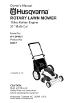
BeatonIndustrial.com | 800-724-4052 | [email protected] I i1 11 !I 1 ! I I 1 iI HUUHHULIB HUUHHUIIB SBISSUR UH IIII HEAD WARRANTY INFORMATION ON PAGE 2. AMERKAN MANUFACTURING COMPANY, |NC. AMERICAN INC. 2119 2119 PACIFIC PACIFIC AVE. AVE 0- P.O. P0 BOX aox12s1 1237 1'- TACOMA, TACOMA WASHINGTON wnsmmnou sa4o1 98401 uU.S.A. SA TOLL FREE PHONE: 800-426-9772 ' TWX 910-441-Z500 800-724-4052 [email protected] __ __ ____ _ __ _______i____'____ir_,,___________.. .. _.._.... .____ BeatonIndustria|.com | 300-724-495 2 | J0n@BeatonIndustria|.com General Information The Hydraulic Scissor Lifts have the load capacity rating and serial number stamped on a metal plate attached to one end of the lift platform. Most lifts also have the serial number stamped in the upper flange of the base frame channel near a corner of the base frame. The capacity is a net capacity rating for a lift furnished with the standard steel deck. The relief valve of the pumping unit has been set to raise the rated capacity, plus a small amount of overload. Where gravity Troll sections, special tops, etc. are installed on the lift, deduct the weight of these from the load rating to obtain the net capacity. Lifts should not be overloaded beyond the established capacity, as damage may result. Unbalanced Loadings Stabilization provided is basically for balanced loads. Up to 50% off balance to either end based on standard lift models with minimum platform sizes only. Allowances are not made for special sizes or features. For unbalanced loads consult the factory. Raising Blocks Under Lifts Where it is desired to raise the base of the lifts to give a greater collapsed height to the unit, support members can be placed longitudinally or transversely. When longitudinal members are used they should be under all long rails of the base. When transverse supporting is necessary it is important to provide members beneath the lift arm hinge points and also the areas of stabilizer hinge points and rollers. Operating Characteristics The hydraulic system, usually contained in the base of the lift table, consists of a directly-coupled motor and pump combination, oil reservoir, solenoid operated lowering valve, and all necessary piping. The pump is of the positive displacement type, and operates at a usual working pressure of about 1700 psi. A fine mesh screen is provided for protection of the pump intake, and a pre-adjusted, built-in relief valve protects the pump discharge from the effects of overloading. The operating principle provides that the pump is operated to raise the table, and the pump is stopped when the table attains the desired elevation. A check valve between the pump and ram holds the table at elevation. For lowering toany desiredlevel, the solenoid valve is energized to allow fluid to return from ram to reservoir. A pressure compensated flow control valve is connected to the ram to limit the down speed to a pre-determined rate under all load conditions. All automatic controls added to the lift must include provision for immediately shutting off the pumping unit at the top travel of the lift. Limited Warranty American Manufacturing Company, Inc. warrants that goods sold shall be free of defects in parts or workmanship for twelve (12) months following receipt of goods. Defective parts shall be replaced by American, FOB it’s manufacturing plant. This warrantyshall not extend to labor required to repair goods or replace defective parts, or related shipping costs. Except as stated above, American Manufacturing Company, Inc. makes no other warranties, either express or implied, including the warranty of merchantability, and disclaims the same. No action by buyer arising out of- this sale shall be commenced later than one year after the cause of action has accrued. No consequential damages shall be allowed either in the event of nonconformity or non-delivery of goods. Rejection of nonconforming goods must be made by buyer in writing within seven (7) days of receipt of goods and all defects asoertainable ascertainable at time of giving ofnotice shall be stated with particularity or be deemed waived. The provisions of this agreement shall be construed and enforced in accordance with the UNIFORM COMMERCIAL CODE as enacted in the state of Washington. Page 2 T _ I ._.. "_ 7' "“ .. " .' .- ... --- ._ __ -a-1--_,__a__-.i_. _ if) B ea 12 °"I"d“5t"'-3|-‘3°m ' . | 300 _ 724-4052 | Jon@BeatonIndustria|.com auggesuons tor Ior lnstananon lnsuanauon 0| AMERICAN Hydraulic Lilts when permanently anchored or placed in pits. ' Permanent installation of hydraulic lifts may be subject to local codes, rules and regulations, permits and inspection. Check your local codes first. A The following illustration shows the most desirable position of lift for the greatest stability when moving loads on or off the platform when in the raised position. .t When Elevated, Loads Should Raised Dock \ Move Off Or On or Truck Bed _[___ Rolling End /Y \ V Over the Edge of Platform Nearest \ Platform Nearest the Pinned Stabilizer Arms “ II v\ ' 1" °I Of GFOUI Grout Under -pi M" M \= Shims mm -"""I 'm Imimrl Channes Onlyy Side Channels Yb ‘ I on | Lifts are shipped on a skid or pallet. The platform or deck should be removed from the lift first. The lift can then be removed from the skid with slings placed around the base frame or bottom, being careful not to deform any of the frame structure. . Position the lift and align the frame carefully so the V2” to 11/4" clearance is maintained around the deck or platform. Level the unit and place solid shims under base frame as illustrated. Where anchor clips have been provided, the bolt fit is close to restrict shifting of lift, and this requires careful location of the anchor bolts with consideration of the frame, platform and pit. Recommended concrete anchor bolts bolls are: HILTI ”Kvvil(-Bolt”, ”K\l\!il(-Boll”, Molly Nlolly »Parabolt or similar. TO ANCHOR BOLTS: TO INSTALL INSTALL ANCROR BOLTS: _ 1. Be sure lift is positioned as described ‘~ §:.::fsi:li li.i2;’i'.i‘°;‘2.‘i.‘i.2i.ifiZ°;'§.i2 . diameter as anchor bolts -~ using anchor .» ....__ .- g 2‘_ £55Z31331l1i1l ?§i11l§1§.§,§§ii3QmWIZ§§§§§l§§§§§§TI‘ " " I-(K-(.2 .t.lg0%?‘ ;,§<>» %-5; _ _i_-_{ 1 Q Mi;If I I // I‘/-‘I °°°.°Q%.i ‘/"I ,g. '- ,. :_' _;_' '=0 ; _"‘~=. =. = '- 3. Tighten nuts securely -— -- be sure enough force is used to spread anchor bolt wedges. (Usually 3 or 4 turns beyond _ _ , ‘finger-tight’.) ‘finger-tight.) H_, _____ ____ ___ __ iliilli ll above. Drill holes in concrete the same clipP holes as 9guides depth cli uides -- de P th is not critical — drill sufficiently deep. 2. With nut and washer on anchor bolts — drive anphor bolts into holes so that a minimum of six to seven threads are below the top surface of the anchor ‘s Q . ‘f \ l \\ H fr’ 9°Q‘; .. 1,1 -.i ;%i'n‘ 3/—‘-I 19 Ci_, ‘?_<,§:gs 9515;. \ I:Q-'.‘.-8--_?§'."f. ,. =._.-'_':'= =._.-'_'.-'= O'Q’:~'-*-.-' _§:?__e:i '=I'T"I'l}_'*._'.-.I-"T:' §'g_ i;,‘§25' !:g'._§1i.f§Zi'-_("_:' _-';'._%_ ‘_. \ _\S \~._ -_'.i*‘!.'-,{r'i,‘;info -"_=':.- ' “P <3-.°<=‘§i ,~?‘ " _ ‘*4-r':;_.__; °\\\°\ '°,9 *Q ;-' o_i‘_§~=8 .=.=.=.? ‘-* °°°. 0' 0 0‘Coo 5 \T. m ";_ '-Oo‘ "' '_Q.»-.-__';--.. -.-5‘(_)_.-°:' ~.-:'<,>_.-°: 2.:-".0<>§,—. ” //I -1-' :-3 AAm_=;.-_ 1-" 9°Q'3 ____Ié%; ____;_g “'1 ‘ 6"'-. A -__I;I=.' if’.-_s_3_-"=_ ~_f;.-:'Ef’.-_;.'_;_-',,-,,;,'-'o%§',=";o,.-» .o:' 1:1‘? '-,i.'_.%'-I:?’.'§'_§:_'_.',-.--I" -,=,'s-:i’:§:>-,..~. "~ Aft er lift ' has been aligned, ' leveled 'mmed, and anchor bolts have been installed, pour 1” of After leveled,, and shi shimmed, grout under entire base frame. When set and cured, tighten nuts or anchor bolts. Run hydraulic hose or electrical cord through conduit in pit wall. Replace platform. Page 3 _ ---- ---'i ---- ' ----~ -'- W —— .7 .7 nu—ni____—— m. __" ...________ ...________ __.. Beatonlndustrial com | 300 724 405 ' ‘ ‘ 2 | Jfil1@Beati:mIndustria| com TROUBLE SHOOTING SERVICE SUGGESTIONS _. fivg \ ; 1 . I 1. If lift will not raise: a. Check electric circuit, pump motor starter (if provided). On new installations of 3-phase motors,‘ if lift does not start raising in approximately 10 seconds, reverse line leads to reverse pump rotation. Rotation should be CCW looking at shaft of pump. (WARNING: DO NOT RUN PUMP BACKWARDS.) b. Check oil level. (WARNING: Do not overfill.) With lift in full up position oil level should be a minimum of 11/4" above tank bottom, with pump unit contained within the lift base. 2. Lift raises slower than specified rate or will raise only partial load: Note: Allowance must be made for slight speed variations due to temperature which changes the viscosity of the hydraulic oil. a. b. . CLO . Check line voltage under load condition. Low voltage affects speed and capacity. if foam is visible in tank oil, check for leaks in suction line between pump and tank. Suction line may leak-—tighten fittings. Relief valve may leak—-observe relief line from pump to tank. lf flow is detected remove V4 turn beyond what is required to lift load. foreign matter from relief valve and adjust to Vi e. inspect lowering valve (see No. 3-C below). 3. When lift slowly settles with lowering valve closed: a. inspect check valve for leakage by removing tank cover and noting if oil flows through suction line to tank. Remove springs and ball and inspect for foreign matter. b. Flush lowering valve by operating up and down controls simultaneously. This should be done with no load. c. Disassemble valve and look for foreign material under valve seat. 4. If lift will not lower: a. Test valve coil for operation. Check voltage at coil. 5. If lift will not raise to full vertical travel: a. Check for low oil level. 6. If the lift does not lower smoothly, do as follows: a. Run lift up and down under load a few times to purge air. '.Ck to the 7. if the Rams appear to be leaking and an excess of oil causes the drain connections '.CI( tank to be blown free of the Rams, it is generally due to an excess of oil in the .ank which is being sucked into the Rams on the down stroke. To test, disconnect the drain lines. N IN6 |N6 \/VAR I\I PROVIDE SUITABLE BEFORE PERFORMING LUBRICATION OR MAlNTENANCE WORK ON THE LIFT. ALWAYS FOLLOW THE SUPPORT COLUMN BELOW “STE” PROCEDURE‘ IW working height 1. Remove load and raise Lift to convenient for access to internal parts. 2. Provide suitable* vertical supports (columns) under the Lift deck (as shown) to prevent Lift from lowering. 3. Lower the Lift onto support columns until the hydraulic ram no longer supports the lift structure. 4. Disconnect and tag all electrical and/or other power sources to preclude untimely actuation of Lift. 5. inspect the condition of all pivot joints and roller assemblies at each periodic maintenance time for damage or OI’ wear. wear. ‘Suitable’ means structurally adequate to support the imposed loads. Consult strength-of-materials tables or consult the factory if there is a question regarding this procedure. Page 4 * m . i. _ . ..._.._.i.---- -- -- -- —- - .... ._.., I IA Q _. BeatonIndustria|.com | B00-724-4052 | Jon@BeatonIndustria| com Lubrication and Maintenance Instructions for American Hydraulic Lift Tables We recommend that lubrication and preventive mainte- nance work should be conducted on a regular schedule, that is. established on the basis of experience gained turbine quality non-detergent oil having the followirig irrg general specifications: Viscosity cst at 40 degrees, C 25-40, and a viscosity during the first few months of operation. The need for index of 90 or higher. lubrication and inspection is largely proportional to actual service duty, environment and application, but it is also advisable to inspect and re-lubricate the Lift following a prolonged period of idleness under severe environmental conditions. The use of multi-grade motor oils such as RPM Supreme Motor Oil SAE 510-10W-20W/20 or SAE 10W20W-30 is permissible where the above oils are not readily available. American Hydraulic Lifts should be lubricated and completely inspected at least once a week during the first month of regular operations. It is likely that such frequent attention will prove unnecessary but will result in the establishment of realistic scheduling. A suitable lubricant containing molybdenum disulphide should be used as Molub-Alloy No. 2 (Imperial Oil & Grease Co., lnc. Los Angeles, California) or RPM Moly Grease 2 (Standard Oil Company of California). Inspection should include careful examination of all fastenings, fulcrum pins, rolling surfaces and rollers, hydraulic connections, electrical systems and general functions. lfif there is a persistent accumulation of debris, water, or other harmful materials present in any part of the lift, resulting from environment or the materials being handled, the Lift should be cleaned and consideration given to means for the prevention of such conditions. The pump unit hydraulic oil should be Mobile DTE-13, Arco AW-32, Chevron EP-32 or any Since the viscosity of the hydraulic oil is reduced by an increase in temperature, frequent use of the Lift under conditions of normal ambient temperature, as well as even less frequent usage with ambient temperature of 100°F or over, may result in oil temperature of 150°F or more. Under these conditions, the Lift can be expected to rise more slowly. When these conditions exist, an oil of higher viscosity may be required such as Mobil DTE-15, Arco AW-46, or Chevron EP-46. Non-detergent oils with a high viscosity index (in the range of 140-150) will perform well at these elevated temperatures. At extremely low ambient temperatures the pour point of the hydraulic oil becomes a critical factor. It is recommended that the hydraulic oil have a pour point at least 20°F lower than the lowest ambient temperature expected. Consult the factory. Do not use hydraulic fluids which contain additives that may swell or dissolve certain packing materials normally used in systems designed for petroleum oils. For special‘ fluids consult the factory. CAUTIONS ~ Over filling hydraulic tank will cause the ram drain line to draw oil into empty end of ram, falsely indicating ram leakage. - Tank must contain 1*/4” 11/4” minimum oil level with lift in fully raised position. - Lift must be empty - (no load) before performing maintenance work. - If lift is furnished with maintenance blocks they must be engaged prior to maintenance or lubrication. - lf lift does not have maintenance locks, block platform to prevent downward movement as shown on page 4. READ THE WARNING ON PAGE 4 BEFORE SERVICING YOUR HYDRAULIC LIFT Page 5 Be-atonIndustria|.com | 300-7 244052 I [email protected] WCOC=Q O5=_CO:W=CflnO-_M_Cn5_ _ Lubrication & Inspection Instructions 9 Q6 k co -cu / -2", ______i ; '"‘) l 9 (DOG 9 3§._\ W SQ‘_@_g gQm ii I sl %i-i/ Q ' V - i.i-e.3.:l.;iI\ E.-It._.. oe _-1 I -mm . i I READ THE WARNING ON PAGE 4 BEFORE SERVICING YOUR HYDRAULIC LIFT 2 4. Visually inspect all ram base thrust pins and keeper bolts to insure Ihi thrust pin is seated in notch and keeper bolts are tight. j )5. Visually inspect all lift arm rolling bearings . .to insure that bearings _ V 5 bc is tight 2_E_w= E6 _U_B_mEOHOG: U_A2OC_qO5U_2EOn_ O_:M®__O _U$5_m2_U9_OC _O j =0 rag CQO_2qC_OsG_O_m_8_OC O5_m n_ gm j _$$__m ®_5C>__&_w mOz_9M_OM_w_8__OC 2D_oO_< _n_ . C. Points noted, no lubrication required (factory lubricated and sealed). I mSEQ 2E _E6Bmgg _m5>__m_§> >___6 >>$_|_£__ _;Q _CoVHg SEQ mC__BC m;E___H 328 o_B 935 8fiw;gC®_8_o 8_ mmcE52 mgmg twmC: 959 __m wjEa Homamg E_n>__gm_> _mmn Em é2352 £8 U5 6n_®9_ 625$2 23 __m HOQEME EG__>__ m_§> up 28 Q6E6 _3$v_ LOHOC E U2 EBGQMuj_(2_afig _r_H_ m:_ _°_=:fl°O_n__n_ _| I Lubrication Points i A. Points noted, apply pressure grease gun lubrication. B. Points noted, apply OII can lubrication. g j _O_J'“_EDO> OZD_<IUEOHED OD_Q UZO >IOZ_>O<n_ EU_D<U_" UwZ_E<_>_ _ so I I \’Q ,4 ii _w@ % g IQW\ \£_"\ W @ Ff?‘/Q "‘ ‘_ _ away‘ Q fl©@Q y,‘“y_-_’_ l / figQ /Q i (IQ ,\ ii Q?’ %%@ G) ‘iii Imlfiimim . ll ti e co \ 6 ®@ . _O0_2fig OH EAgC_: @_$8: Em £_HOUQWE Q:w_E3>__g2> Gb:_U>£ Inspection Check Points ‘_>_HOQ__ :1u® :2 CE E5 9 ®___o__ U23 m_QD__@ _HOOQWE ES w_0Cm_6 o>__m_§> _U Hg:255 OH maU5 m_ ;®__@ 25 v_E9O_U_WC>_@O_m_gOn__N 2_> 2 BC H_W2 E5 'v_8_ _2 ®_2_62¢ E _On_ :_~E5u_62>O__gm_w___ C_2> H8 25°“v_8___0°_ _°2_m_ _ j 2j _®>O_ _ _ 6. ‘(Heavy duty Hits Only), Visually inspect all lift arm pivot pins and s~ screws to insure that set screw has not loosened, allowing pivot p to move 2. Visually inspect all ram crank pins and set screws to insure that set screw has not loosened, allowing crank pin to move. 8. Visually inspect all electricallines to insure there are no chafed lines loose connections. 3. Visually inspect all ram crosshead roll pins to insure that roll pin is 9. Visually inspect the entire lift unit to insure there are no structur U220 MOE:QCEM2m255 OH vmOH032: _‘_>__MOm_:O_® __£_@> jg,_m:=_ m_ _\ I 4 \_ Q failures. fig '/ _3o:O:EmQ65 E8 Q52: “E :wB®n_mc ®Qt 5\_>__Em_m:w__> $02_ wCO: ®C_ O £80 OH CE mC_HOC _®>8: O;298 _O_U_QmC®mO_O_ seatetwrrectly. mC_vU2B$m_w_8:m_$__Ot_u_ 7. Visually inspect all hydraulic hoses and fittings to insure there are r chafed hoses or leaking fittings. _UmC®wo _ 1. Visually inspect all lift arm pivot bolts to insure that lock nut has not loosened. Beati:inIndustrial.com | B00-724-4052 | Jr:in@BeatonIndustr|alcom I M-500-MM IVI-1000 _JN<OOTN:_Oh:_ O_W__ I A °_ 89-: _z_>___° m_ E i @ 4.1I,--.,-. M 1170 2A Thru 2L Senes T’ s ‘ nuQ \_\“ To order parts, you must include withiyour order the model number and serial number as shown on nameplate attached to end of platform on Lift. A" ‘ _3% j£_\_\ _L%oE “DE m__t $_U__o @_JH®36> o__%__o O___| Owm>_UE3I \_:‘U_CSwt_ U6 _E6 U8 g_ mCOC: QECoCgosw _mm__gE_E Ufi~B_H_:n_mO_ E_mO_ltC__W_Q ‘T’ A _g_w___° _,A :°“tum =m\°= _ _w_uU_ General Parts Identification fig ___ _ Lift Arm Hinge Pin Assembly Outer Lift Arm Assembly >®EQO__| _D@EQwm<_ H_ >_6N_n_ED®gSm< >$_NDmE_®n_WW<gm _O®>_§ >>O__:COOH_ H5 >_ D®E®_;O|_%(E__<:3 >_flEQ$< Ea 6&3 ZDmégm $E_QWWQO_"_ O__JEgI v_Ew__' Upper Lift Arm Assembly §_O_>_ Q__ _5n_ Roller Bearing Assembly 55%?‘ 2;Ea :3 Lift Arm Axle Assembly _U_®>_G> OC@_Ow Pivot Bolt Assembly figw>H_n_OEH$_2 _n_E§< “>E_DEmHm_ %O<>_n_ fig>CE ezfiva Stab. Pin Assembly :3 >____C< _DE_®LWw<®CC_ =5>%C_I $_ND_EmD$_m8< :;_N® _usjQ_g_<_’<u_ ;_ _ ® -v -@\\_ :_ §2_Wjm_,Nw Wd_W m_,wm 5<5.'.5.§.E?.'S.§...L.!.!’T ) \.. ./57i!*\’/ ME W M\ NAMEPLATE r-S. 4/ er‘} ie-i. ____ :3>E_< $_n50E%g El:3>QUE: _nE_®8< E3 TYPICAL %'1) M ;\// ;i _gfig Stabilizer Hinge Bolt Assembly Flow Control Valve Hydraulic Tank Motor Pump Solenoid Valve Foot Switch Assembly inner Lift Arm Assembly f‘@_@U__ __LQa‘@I__l Lower Lift Arm Assembly 6‘I/\ _ _ Roller Bearing Assembly at,3, _/®/_ _H_if G W H _\ I f %/a@/‘_ El QmfimEME ‘ _ Qwgg/fink @If U_Y UM>_DE®8< Emm mEm&_O_ O B532 \\ i@ 9 dW%.M,_,_ QJ\X Stabilizer Assembly iigg \_ I fir‘_$ Hydraulic Ram Assembly \~\ \\©g Stabilizer Assembly / A Ram Base Pin Assembly -.,____ W1 Top Frame Assembly > >_o_E%§_EfimO_>_DE$g_ m__‘ M_ _ _U>_@_®m‘$__Om Ram Crosshead Assembly >®Eafim _QME_m_Hw_ < Base Frame Assembly W3? @ i?%'@ F BeatonIndustrial.com | B00-724-4052 | [email protected] 81¢“ N°N_lN_ l_°ZN_hO_>N_'_FZ_°hZ_ _ Z NI-1202 Series i mmt°h_ dO_hw=_mO_h5_ _ 5_ fl____kn #1,‘1 K fifiiF)JIM \ \@ is R Q 7/M _ jp l lVl-1170- 2|“ M '-|17o ' 2N lvl-1170-2P lvl-1170-7A IVI-1170-70 Series i it T ta "@':' -re Ga“ ‘ 3 --f""" O i I I I I r -1-.--.-—-/' - --- ’/'- 1| ‘I L_ Q _" I ii’ L \ _'\j ’ _ _" gQ g (JIIWHIV M_HMI4% Uj ‘E 1_‘ W8QU“QwnqV X_$Q_ §\”_/x M it \. ..,_...|-/ ___ “"'-.__ ‘In- --. “'\I-5 -...,___ “""--. JO 9 /"5 Qe \ "“"--._ ‘E6 e QQM 5, i; //\éfl\\ / ’ ' -iii. PLEASE REFER TO PAGE-7 /w NO____Em_ogmznz mwmw<dn“_Om_zO_|Eonmom_H _Em_O b\ Q%__ FOR IDENTIFICATION OF NUMBI? ‘ii WAXG W I 8% 0 \~ \_ \\J05 9 - WeM E K“J _4Q ‘“‘ _\L , ., (Q E\ ta \'6 I U -5,‘-b ____ _I!’ ff" _ _‘___ I“Q _ H re -1-.‘ --...--. f/ I I 1 I 9 9\\/(yd, “M {Amg M - -t -~ I.‘- ‘tjax$3, A‘‘! vi t,/a . - n_. ,.- — I . /* I Q” ‘W \@ _-—_4 |:®g W \QM _m/y QfilX‘ Ma‘ xggsJ? jg} \\ I / T \\*: - S t Q BeatonIndustrial.com | 300-724-4052 | [email protected]::im _ _ = \\) ‘ i i 7' TE’ -1- El G 7-iii?’ _// ///_ "FEW i’ 7 4L I i j _ WW M__ H_“WAfHUS‘fN ; E jf——__ “' ‘AIMlMM‘AlAQ‘l A\%‘N _ Torklift T1 Series 3F =$20“ 'MNNF_8:0“ _°_ _IE IVI-1223 Series I LQJ 6 (E O e5fied I. {iii @"QT‘"€ W r ,9 g Q K Ii;-ii‘ _b .~ °“"‘””@,@ E .\ a~= I - / E : _ _:.‘r:_‘ 4| Q it j \t mmmlN w"6 zI_Om_"w_<Eom_w<“ _>O“n|mD_z7wO__O F FOR IDENTIFICATION OF NUMBERS PLEASE REFER TO PAGE-7 _| @ I fl________ 1_! / ;__W %N A <-5 \j \ ‘ll _ _?_ _ _ _ &\ . t ..,. mMQ__ / _\ \M H \_\ U H\ 4"--.. A i\ \ .5-9:,P I ¢ _ @ _°9‘P;W %M Jr‘K\_HA[K_ I I Y ,7, I I -.:__- " _\%I. /1, "" tn‘-‘ ’ 0/. ii‘; A2 . '\ €“'--.. Qi .2. .. O .1 H3 °P .3 I ’ __ m _T‘Hr _A S _M MA\A M W/\ \ Lm/_fly g \ V? ; W; 6/ \__@' F _\_\\_. \ I_f__P_'_\ _V 'I I.-. /T -g .,.____ lfiii i V F@/, \/ah _‘/_ Im_£___ R M ___vI_l/I X ® _ \ ’ iv mp gj % W Q MV_ . 6 gt; " ,1,» /4 %@m Wwfim fgfifi? W % §©@ F@L___g_%_ _W JM $0‘Q fig __m' _I_!6'g _A9im %fi96.tM m i__?_r% %%A _ L3" --it ‘~\ \ ‘E a as av% 3 /T . ’/ aI\\_g§h_ 9 A (C7 slcfi / ’ k @6 5 O ,,.Li ./3‘:'@@' '-,\\“\ $0 ; “Q H &‘ 6‘U8QVé / \ 9’%“_ -\ i/:-5.!/II" - 8:5 - I ' ____@gt _57% e5 . el lg] j 9° @\i m"~--Q-om .. I X € Q? 6M jg l I Beatonlndustrialcom | 800-724-4052 | Jon@ Beatonlndustrial com Motor TYPICAL’ TYPICAL PUIVIP PUMP '---.\‘\ /' €\$TS J $€ Q 3 t V ‘ ""\u_b U NIT Si 5/) é ET“*5-=. i-._€;-1:;__./... __ Motor Pump_Adapter Pump Adapt & I -_,s:%-.?:_!=_. _:_—."_?-_____:-/ t\lll|"'Ifl'I$:tTl E olenoid Solenoid Valve J ‘ a Q 4-n Coupling Shield .,g E l . ill'@ *I%:i<~5§' ' IIII4 '*."!.-'5 - ‘IF "N--» _ir.r/AU"'§§ _llll QF -i;‘:"";l!|l|ll| I: I:-Im WA Q Q ‘H 1 -_.. --\ Electrical Control Q‘ . \\\\i;!. \\“! / ’ $5 _ V/‘U 1/ml - ‘ll’ I’ 5,?‘ 3 .“i's ‘ill Qw it --2 AEis»: "1' 1-iillIi‘ ii !=l 3 T ' :1‘: .'== I='-'>'i;:=. E1 -fififli ¥\ \ EN? —-\. _-\ Qfirti e _ T“ V 6/ s4/ l l Filler Breather C Checkk Valve -.\. G --1-"T, ‘-- -I "9'-\§)) 1 . Q3 9 .5 _ _‘ _ _ ‘—_ 1-r-E I1l l ./.1“-"' /=-ifF‘ ro up I PAMsf J:-.-. ~ _ ' _5~'__,.l.; ® HE‘ Ha"-=-_~.§=§___T_¢___\\%%=\ ._® my I ‘i1i:_ Pressure Pre ssure Compensated Flow Control Valve Hydraulic -Hr '—' Cessna C essna Hydraulic Pump e weI /E: ifk, PC 0l.."“mitt Cw '~ I llQzg -~\_ ‘ ='" “"-~l';;=- =-‘ .— E Hydraul Hydraulic ...»Tank IC N Q‘. Q Reservoir --p—_ 6 Electric Motor K MOUNT EXTERNAL TAN TANK MOUNT _ D TO TO LIFT LIFTI RAMS ":';__../ "7 W \ il ‘/\*2 / I1/ /"' /\ . / 0'“ x _../' - _/ .._-)- ____ \ M 15". ’ ‘Tr -. '0 1-‘ r‘1," \._\__\ ‘\. .‘ ‘ . 1. '1 C Z.,./Pump KA“l‘ §Y_7'{;~t /iv’;X / ‘ ‘-\.‘“ Electrica Power “ Electrical Supply Connection Box ‘ x .I’...:7';r;§ \\‘ fiw“ I oid ' Lowering Valve Solen Solenoid \ rol Enclosure Electrical ectrical Cont Control ;/ Flex Cord to Foot Switch Flex. or Pushbutton Pushbut ton T AN MOUN PAN MOUNT EXTERNAL EXTEFINAL P Hydraulic Reservoir \ Electric Motor ? or lgl’ _;_g _;_j I/\41 ii/\\\ I. l” 1 // // . % // 'I 113;. 53% “‘"-t ‘Qo _ X ._ 1%/’ . sq” !rrr':'i:\ _ *~\ (.- 0"" A ;;,.‘I.;-.///"' _ / / °/ Electri cal Power Electrical Supply Connection Box Bo x (3 Phase Units Only) K’ "'\ , If": If.‘ l1:-;-€!'r . ""'Ill| I . r (nit-turn‘, ‘- ru- "-.. Xx_ ;'/ ’//F Q / 4;,“ -4,, N‘-\ Q , O :' \ ‘Q 1 "Ir ", 10"‘ i .4 91‘ P 4" cl "-3i~=j%“*-5'-"‘.}‘7?A" § ,0 '( . P In Flow Control To Drain Connection At Top of Ham Ra m I \ \\\ H 3“-:. if/-""f \x r 4,," V "“"§\ ‘ii--|i~a\ Pump '3 noid Lowering Valve Solenoid Sole l Electrical Control Control Enclosure Enclosure Electrical (3 Phase Only) \\ \ Flex. Flex Cord to Foot Switch shbufion or Pushbutton INTERNAL Page 1'0 Im i ._ _.. ___ _...-._..__.__._.-_ _ ._..__.__._. . .. ..._.._. ___ ___ ___ ‘ BeatonIndustria|.com | 800-724-4052 | Jon@BeatonIndustria|.com Pumps Nipple to l Down Valve < Check Valve Cap I Note: Use tape pipe sealant only. D°“’“ Va "9 _f.- "ram-_._ " '5. » _ 1 Relief veive__,, Valve____, Relief Poppett _ ' 3 _ 3:.‘ l. , _' ..; Check Valve Ball I X \ H.- ‘. _j- _? "<~- -j -=1 _ . _;-' '._;I==§' ,==;.;.-=1--; " -'+‘-" ' _.-=§:..>‘ -. ;.-e"-'=5ifi§*?> .,. '- E IIJOW Elbow _ If ’;._ . ,., - Check Valve Spring 1 ._ __§ _»-. ,, ._ __.__'m:i 5:- I ii: 1; is._ ._ ixiz; .. \_‘- .-.. .__,.,.. -'1 --+.v" . -. N-- | V _ g Nmple """""' I ‘pp e "‘""" \ -r 0 -Ir .li . ii ;,.,i_' '@'1"i’..'e;:,-‘*»r"-; Suction Fitting ~ l‘ I= Fitting .. .ge‘"r_5i-= Tee Relief Valve li Spring , | Nipple $ _;_‘ U,-ii... . t - -'1 ., .- 5: _- -: _' .- - _,:r.: '=1- "‘ "’_.J-j __?:-4.. _.fi__E__:-4:. Swivel *'..._..... ;-. II:..~...;. Pressu re bressure b_v-Pass _V'Pa55 fitting _ Relief Relief Valve Valve Adjusting Screw Iii“ (0 , 315,- . A . -.-- ("'' W *" '-.". ,'5 Street Street Ell Ell_____..,...,@, . to to Ram Ram \ Pump Body Relief Valve Cap M\. Pump to Motor Coupfing Adjustments ~~ ~~~ If 1.;. _ j’._ ' j:'--ri:':!;.:j- I-I.-f-'=f:i-e ...... (“.4-w - ~» '1:5. -9‘_'-1"; ,-L... .:f-‘;::<_' _.'§9 '=' -.=. Caufion ' Do not operate this pump against the relief valve by overloading or in the extreme raised position any period greater than five seconds. When The built-in relief valve is set at 2000 PSI at factory. Do not readjust to exceed this setting as full load working pressure is 1700 PSI. “Automatic Return” controls are used provision must be made to stop the pump immediately upon reaching the raised position. Service Do not run the standard pumping unit continuously Do not attempt to replace gears, bearings, shafts or other major parts of the pump. Order a replace- or. use on applications requiring more than five starts per minute in continuous service. A special pump unit, externally mounted, equipped with a idenfified by the nameplate data, ment pump head, identified Vllhen assemstamped on pump body and plate. When bling pump on motor be sure the intermediate coupling aligns with motor shaft slot and pump tang. continuous duty motor and normally open by-pass valve can be furnished for high frequency starts. Check Valve Cap Screw Check Valve Ball Check Valve Spring Relief Valve Adjusting t\\}\\\\ \\\\\\\w ' jnjet __+ Inlet--p - i "L". .‘§_r-‘ H-.. .__;. ff iii‘ '._g'I . kl‘. Relief Adjusting Adjusting Relief Screw .-Iv .-Jr ‘Q. . S fie all-ii- Ijlillt by ’ \‘\ F . . R Relief Outlet __.,..i ._..... .|-ijiit To ‘UL ' To Tank Tank ,1 i2%,: li i,ii.'.£' ~. .. II \ .\ \\ -\\\ _. _,_,-e\\\\\\\_\\\a \ \\ M \ Relief Spring % / ""—' Outlet zW/7 ""/, a -W/ /é /’»~ . 7/i Q ' %%/ A Drive Shaft Seal Relief Poppet . -; ;._ .-._ ._-_ :_._ --; l © 1 I l N llllll \\\\w ® — I % 7 © gfilii Zfgiifiidiusting Screw Cal-3 Nut intermediate Coupling g '.'=:"e' _. -L:-Tr i=‘-'5'.-" J7 -D. ,;;_.,_._|. ">1. _, Page 11 ' Nameplate eatonlndu t ' I. _ . 5 Ha com I 300 724 4°52 I J0n@Beati:mIndustr|al.com ,___ Cylinder Base Pin Pin ,.-- c Y linder Base ... ___. Nvlon Nylon Wearstriii Wear Strip . Il, T-"9" ,_.”0” “"19 Ring l #i= Stamped Model #l= Strip Wiper 3109 \ll F. Cylinder Barrel 1 ‘I RRod ' ._\ od Guide i Wife Smp Snap Flifig Wire Hmg Spiral Retaining Ring ~ [ Cross Head Pin _, 1A l O... O--e-. O--s-. ....\€ if 1' -.:i=‘-,‘-:‘§F<='I';;;_ 6;. ;_==*3" '=='I'=::. -$jEji:'5:=;:"' '!T'f- .- ~ -.-. W \. -. i, it i @ Teflon Backup Backup l ' Rmg ,, . O O Ring “mg fi A \ ...‘, ».i Piston Wear RI"!-J Wear Ring Il Rod _l Rod_I IO” Rjng ii *0” Ring ' L._ Oilite Bearings L._ Oilite Bearings I l_ Flexloc Nut R0" PI“ Pin R0“ 3. Repan Pans Repah When ordering parts specify the Ram Model Number stamped on the base of the cylinder. A repair kit, consisting of the following -parts, is available. 1 - Wear Ring 1 - Teflon Back-up Ring 3 - “O” Rings ___.Cross Head --Cf°$5 Push the rod guide back into cylinder bore until the wire snap ring is accessible. 4. Remove the wire snap ring and pull out rod, guide, and piston assembly. To replace Wear Ring, Teflon Backup Ring, “O” Ring, Nylon Guides and Wiper Strip, it is only necessary to spring these parts out of the grooves and remove them long wise, over the lands of the Piston and Rod Guides. 1 - Nylon Wear Strip 1 - Wiper Strip Disassembly Procedure A repair kit should always be on hand before disassembly of the rams, since all of these parts could become damaged when the piston is withdrawn from the cylinder and pass over the snapring groove on the cylinder wall. Discard any such damaged parts and replace with new. Disassemble as follows. 1. Remove drain elbow from rod guide. Assembly Procedure Clean Piston and Cylinder and Remove any scratches or burrs that might damage sealing parts or prevent proper sealing function. Lubricate lands and groove and install new parts according to the illustration. Reassemble piston, rod and rod guide assembly installing the wire snap ring and spiral retaining ring in reverse order of disassembly. 2. Remove outer spiral type retaining ring Spiral _ , Spiral from rod guide. Wire Snap Ring Retaining Ring H0” “O”R'mg --P‘I5t OH T B fl OR Backup B BC k Up Ring R‘ITIQ “O”Ring--Piston Teflon Wm snap Rmg /T Hamming Ring ' “O” Ring_GUIde Ring-Guide Wear Fling "0" Ring--Rod End Nylon Wear Strip Ring _, ‘F| .i'' " - II ' I ‘I E‘-. \_:_ -" \ ‘X \\ \ n EH#Ii T1‘ 9% Mfillli .‘ .‘ ”I 5 i,l INJ‘ ‘Ml iii ll 2-i _ yi 1V, ‘Hi ll . \ . -.' \._ TR XX Y\§L\,,\§ L Wiperstrip TmYYFL \§t\i<; XX asem. _i ,,,,,,,,A ,,,.,,, 1 3‘gag ' ‘. \ “\ \ . , .\ 5?;-\ \~ ‘ /' .\ ,~ - i‘ . A ///fr /v. (/|{/ ’./ *1 ‘ ‘ . . N; l _ . \S"‘ \ I ll l l I""'II‘ I‘ HI‘ III ll Il | .|‘ ij ll lllil II‘ I ll,‘ liH Hll l-li I I Ii‘ l :-.c}%:i=-la i'l ll‘l\j _ J _1_._.*‘\==,,,, \ is i~I§|_‘.$w~it53I ‘we eifsmsai. ‘‘. lk It L i ‘ ... I ' Rod \\i\\\\I.\\\\\v.\\\\\\\\\\\\\\\\\\\\i\\\\\\im\\\ \\i\\\\I.\\\\\v.\\\\\\\\\\\\\\\\\\\\‘\\\\\\im\\i ]\ Fl8X FIBX OC NUT Nut Piston CVl"'ld°' _ Rod god Guide CYIII"IdeI' .0. ,,,,,, kn Page 12 Page12 € i—-— _ _ i _ .. ._.____........_._...i.. ___... ._ . . ..........._._..,i.. ._.. .. .__..._._ .__..._. _ ..__. ..___ J_ — BeatonIndustrial.com | 800-724-4052 | Jon@Be-atonlndustrlalcom Hydraulic Schematic Standard Pump Unit Hydraulic Ram TL Note: Lift may-have two, three, four, or more rams. , ri \ li Master Flow Control Valve (Used only with two or TA more rams). rI IN Io [Z1 HYdHYd- H°$e H059 Lowering Valve Normally Closed Check Valve llll I Q O "' Pump 1:‘ Drain ~ l__l it -.-. - ,y 11-11-iisf4A_ ‘ Flow Control Valve (controls down speed) g _. _ L.. . . .-I Relief Valve Strainer _ | Relief Note: Check Valve & Fiellef Sta-Rite Valve built in Sta Rite pumps. External with pumps. External with pumps. other pumps Tank #3-cs-3 or #3-cs-6 Normally Closed Solenoid Lowering Valve Service ln the event the valve malfunctions check for burned out coil and/or foreign material in valve causing failure of valve to close. Check for pos- /-V'| J sible low line voltage. Z Co Coo'd 1 e 1 en d Soeno' ge 1 r Card etr n’-_. ‘T,-' f Remove nut on top of solenoid. Slide coil off valve stem. The stem is threaded into valve body. Take wrench and remove valve cartridge from body. The valve seat is held in the valve stem by an “O" Ring and can be removed by grasping firmly and pulling Reassembly j . .I Lva l_Vavvgee j u.-.. ¢ .‘tT. 3.. . -5 -. ia; PT: . '7'?-_;l' 1 it ‘ .1. f. > ,. _. x =.> " "' 1 . .. '1 "-375: '5 . *1. 2 .i' .1. I. - if " ‘.3. ._ _. if ’ .. l. Body Va ve -r-_.J _ ‘E I I,-‘J |;c_____;_.,_ """"""""”r l Valve Stem _,,.._..Valve 1 Page 13 I I . o r 4 0 I I ,./533" . , 1 . n n {$37 O Ring Ring -I-- 0 14 L ,_ ___. ._.. n O n Ring Rang _,,,_______P|lot Valve _,,,_______Pilot Spring , When ordering parts, specify the valve model number, pipe size, and coil voltage that appears on the nameplate on top of the solenoid. The valve body, valve cartridge and solenoid are Ring Kit is also available as repair parts. An “O” Fling available for service of valve cartridge. I : I - fr I - ____ ___ Pilot Valve _,,__ _,_ Valve Orifice “H7 -q-- Orifice‘ Repair Parts _ I‘ I ' Reassemble in the same manner ‘as disassembly. Make sure valve spool and seat are clear of foreign material. Check .“O” rings for damage or replace with new kit. Use care in reassembly to avoid damage to “O” rings. fil’ .- 153%-Y--2'* . I Disassembly Procedure apart. Carefully remove the valve from the seat. Cartr'd %- __..,._ Valve Seat ......._ i i \k._',_-ii-"_J“ \"-.-_"" .<—=. -"— Valve Cartridge (exploded view) non Bin |q| 9 BeatonIndustria|.com | 300-724-495 2 | [email protected] FIUW UUIILIUI VOIVU (Controls down Speed) - 5-. Hydraulic Ram aYII\bIIlT|Ih|u|||n~|_-' (controls down speed) -—‘ - --‘ It ,. Oi ‘ I-= Continuous Operating Pump Umt Unit l Hyd. sV - .._----_ \ Master Flow Control Valve l (Used only with two or ‘ more rams). v Hose - _._____...ll Note: Lift may have -S two, three, four, or "‘°"e fame _ Ch Chec 9° . ‘ |4r‘W ;"?w\ E v-2 k V l K a Ve \;a|Ve Lowering game Q §lI Normally Closed NI fll V i "" '1 ._________J _ _______1 |||-1 ~ ll l____ Relief Valve Up Valve Normally Open Strainer NOTE: Relief Valve & a Check Valve are built in Webster Pumps, external with others. -, #3-06-3 N-ormgally N-ormally Open Solenoid Valve lor Continuous Running Unit bi- i _,___:_~. .e_______-\.. N n i Repair Parts V When ordering parts, specify the valvemodel number, pipe size, and coil voltage that appears on the nameplate on top of the solenoid. The valve body, valve cartridges and the solenoids are available are repair parts. “O” Ring kits are also available for service of valve cartridges. Specify whether \-"5 ‘J -ti normally open or normally closed cartridge (cartridge is required. :_ § l sl, Solenoid Coil Valve Stem Service ln theevent the valve malfunctions and the lift does not raise _,,_..__"o" Ring -check for burned out coil and/or foreign material in spool valve causing failure of valve to close. Also check for possible low line voltage. Disassembly Procedure ...|i.......- Armature Spring ...|r......._- T Remove nut on top of solenoid. Slide coil off valve stem. The stem is threaded into valve body. Take wrench and remove valve cartridge from body. The valveseat is held in the valve stem by an“O” ring andcan be removed by grasping firmly Valve Spool (“fl Reassembly Reassemble in the same manner as disassembly. Make sure valve spool and seat are clear of foreign material. Check “O” rings for damage or replace with new kit. Use care in reasT l l T Snap Ring Valve Seat ..4---'.".f'../ -4-- "O" Ring I and pulling apart. Carefully remove the valve from the seat. sembly to avoid damage to “O” rings. Armature i Q __‘_____ Valve Body g@@@eeE Normally open valve shown exploded See page 13 normally closed valve. Page 14 . -. -. --.. _ __ _._________,,i..~?_ _____ .._.._ é -__....-awe-_._.. -___...-{hi-_._.. .. ":1 I Beatonlnd "5 t‘ _ "3 I. mm | 390 _ 724 _ 4052 I Jon@BeatonIndustr|a|.com ~ m_ _ m_ _ m _ .mr_ L_ 5 Wiring iagrams _Jm; o_mm .. "l."'.?'37.."B.. . __=:nE:manim:°_ L:_c=_‘:_ ° .. W5‘: -8€'°!..... l Three Phase 230, 460, or 575 Volts I Motor Starter with "Start-Stop" Pushbuttons in cover _m>OU c_ _ J ' Pr Transformer in-q omjm _ * Fuse - 115V |-| _ _m_ ‘_ wE Q -ii-l—————‘-I v Solenoid ' E500__E, V2 L__._.._.__._.. | Red Lowering Valve ve Um o_O>_“mEBz \N‘uA‘ A‘_ _U®>_N> _O_ _Q_IJII Ow g g "-l‘— a Normatly Closed CO__GHm CO=_“OE HO ___U: 5_ _w_Jn_;m Foot Switch or Pushbutton Station 526 C020 Green Green white Xofim __l_. Down Motor with built-in l thermal protection My .. \ _ .r_____. ""._'?"'."'.T.T"T""—l Solenoid Lowering Valve l _]lI l 1|‘II‘"J I I wi_uw_iICO'_IgC_®@_,O$Ow|_ Red Umm ‘I1. -—l—— . i" __________/ \ ll _’@-%% I’ _ 58 . 8__ _ l White Lift Pump Unit _mE6£ Cgowga _mugs i @255 E?___ C_6__ 52___ 5 __ r __________ ll l‘ ‘I E5:_|_|\‘ QEE CONTROL CORD _ L_ 9 . 8_m____n_ u_ _I‘_I§io Grounded Plu 23> m:@_mEm _2__U___n_ =_“Eat _m:_°_:_=_ o:_ _m_ Single phase, H5 VOHS POWER SUPPLY CORD DECOOEOO >|N_On_mwn_>FDzOwOm Intermittent Running Pump Unit i m_m_>_ _hgm w0>_$OJ | _UmO_ O_Ow _ Down starter. Solenoid Normally Valve Open ‘ __ __, . _ E500 " Solenoid _ l Green j v-1 Down , , | Up ,._| 1 . l""‘£$_‘?__. .___ _. >_ mI_ _ _6z Bi O@>_M> _ _h Q_Ow :30 _, _J__ I . — __'> efied gi —— l fie ___8_w__ — up __- provided with over-load protection in motor __ _H l |___ _ Q; Pa 9 _e 1 5 LL-.. x2 ' l l Q-——-—"D 115V 9 j BEN_ T‘ _| I 0 I L x thermal when 1‘/2protection HP or smaller Larger motors are _ \‘ M--1 I FUSE» _ _ Fl Biack Note: Motor has built-in rS I Foot Switch or Push Button I fi lIA I , I _ 16 gm_ START L W_Ia ___ ___ _H_<Pw f 6 ‘ l I __,,,_-—"'-._'7._.."""‘“""'._.--- 1 l Motor Contactor 4 l’¢'-"""_'_' oUQBWOB _ _ _Q>OI P_Oz3m_Om_“,w_%w_%DHm bQ; Q_O_ =fiCUESEW “_N5; _W2 _EEO: _ “£02 _ _ _ _n_ _O:COO n_____ Nxan ' _ Control E BEE COZOBOB 5:v_ QG_m E855I _ _O:U@u°_abl@_l_Cl2hmCml_i‘l_iNxSA“O MEEOHOE 6=£UFOO“ 3_ _$w X2 :1 P-2 L_°662 _O_w€ EO X1 i I H4 _‘I F: I H1 Nd E_ _k Fl l ll e 5._ mcozgngwjm_ _H_O_w_:9wfi_ I E?Bt_2O5_gw _ - i i _. - ..-."""-i ____)_-_ 1 Oi _I .. i 6E2 ‘_ 1 mg “_O_m__;$_w_8N 6% _ _ _"P 23> Em O62 33“: $8_ _ _ Three Phase 230, 460 or 575 Volts BeatonIndustria|.com | 800-724-4052 | Jon@Be-atonlndustrial com \i\€Ill\iIGlI\iI IPI,\iII¢;l\1III\: I2I,\1II Iil\III\I \I\ruo-awn \I\riii-0-icrinrn uniuuwa uniuui--a Reference Guide MM-500, M-1000-B, M-1070-1C, M-1070, M-1170, M-1202, M-1223 V" 1- __:: _.:: __ 2. '— Price Ref. No. ___ W. 1 — 1' —— ____ -... ii —: _ Liit Lilt Lift Lift Capacity Travel W’ ._— _. _. 1* '— Base Frame Size Collapsed Height _esw : 1* _.. 1"F' 7. _. 1' _ " F’ Standard Platform Lift 7- ’T|~ ’*k- 2P 2'PP 21 Pi — i 2P — —2—P ~12 "WP Model 7 P 2P* Shipping Weight 35",1 _-,1 3592 300 ,1 5” 12” x 12” x 25” MM-500 5" X 25” 500# 25" 500 # 25" _ 39° 2251/ . " 2222 21s=/.~.(34=/.11 ‘ 221s=/mt 341/."222 2 lvl-10002-B2 FF91/ , PPF P‘ I 6 P%"XPPP3P4%PPP' F PP19=/mi 941/.~FPP P l v l 1000P-egg 90" " I0 1000# 30" j 435 ‘E? "P2 0" 171/2”x M-1070-1C 9" 111/="x 491/2" 24" x 52" 92" 1500# 48” 43” Cal 429 g 2 2 4252 52" 2221211/=2"11224121£" 2 12s2"222x 42"‘ 22 2h2I-12072022 9P~ FFP1F-11/.~;a1P1F/;~ P 1P6P' P ' P PPX 42~FF P FFi 0 -1P0,10]; 2000# 36” It 6 1119 1P" 2223" P 29" j 2x22fs92";"2 Px P99‘/2" 2235" 99" 11x 122" 12" 2P 2 in-11210-22220 in-1110-2Po 2s20"22 2212" 11152 _ 20004; 690' j 2 2000# "1100 2P T1100 210" 2292" Z xj251/2" "_ 2224" 2""i2122s"22" r.1;21110-2a P10" P29? L xP_1P51/2"‘ ,_ P24" P,i P 1PP9"PPP, i.i;P1110-2i=,i 3? 022069" .P2°.°P# 2212:. 72?355°. 1. 120" 231" M-1110-2K 200044 5.4". 9,4", 10" P91" 2211222041/Z" PPxPP94vEP" 40" 49" 211295" P299" 2P iiii-1110-2iP<P __ 29°°i‘*‘ 93° _ 1"22 242"22 1" 2P 232" 22*" 2211 PPx 532" 99" 24P"PP 11250" xP60"P 2P M2-1110-2c iviP-1110-2c Lg. 930 PP 230002# P 9000P# 48'2'2222 4 2 ‘*1 22 1295 1295 3" 9» 2F 23» 29» ."§31/.1 £941/."FFF 33» 99» ".1212 FF212»-+ 2F M-12110-2|. 0-mo-=1. -LIO -LI'D 22222303042 FFPPP90004 ""27 i6 3000# 9” 48” M-1202"-3K _21 9000# 60” 90" 9" 3 31"’ 91" Xx 94” 94" 49" xX 96” 99" NI-1202-3K j6 2200* 2200, ‘MOP 2210" 2P x P41"PPPP 2123" 225 PPP5 2P 2PP 4000#2 4000#P as"22 99"PP 2PP "1" P1” PPP19" P19" 2.12423" Px P4PP9P'P'PP 22211-11210.24 PPM-11P10P-2A P 1402 P 110 "110 23" 24" 11X 40" NI-1170-2B 29" =1x 41" 49" lvi-1110-2B 4000# 36” 22 1" 2sP6 2 40004522235" 1210 6 1210 23» 33" 23.F1. 61.2»-*2 121»:-23.31.1" F93 1 _90P"P 99»-FFFFF 32" 92»! 1.3221» 1F9F1~ 21.Fi.2Fi1.3.1;0F=;9i 222219 PPPP19 2P 2P 4000#222232s"2 4000#PPPPP9P9"P 1475 P9" 22230"2 P 90" i22102"22 iPPP10P"PP 2235" P99" i£12" ivi-1202i9|= PP 1415 242 212" 22PP M2-1202I32|= 24 2P 400024 4F0F00F# 422"2 42* 2 20" 1055 1099 3""2=31> i1.1-1110-5.1 n-11210-223 9" FFF=F9r> 353»3 F54»F 2F ‘=41 F24" .1360 X F90» 1310 12FF 46334 40004 1515 1915 2P 9" M2-1202-as 9"P 2223022" PPPP90PP" 22{202"222222 PP{P92"PPPPPP 2P 23s"22222x2a4" P99*‘PPPPPxP94" MP-1202-99 22222202 PPPP2P0P 22P 240002# P4000P# 2P 4a"2 49"P i d A ~ — W15“ 72"’ W 4000# jg 722” _ __ -. ‘I041 "1021 ———T—_—:____ :1? T6” 31”m x 76” — 36” f *. _ _ — __ _. _ L: 6,4” xX 84” _. 1" M-1170-2P (2525 7* "2525 3000 941/=-"PP 492"22 49P"PPP 112952" i<P99P" 2P 22PP jjgni-1110-2|u22 Pgiiii-1110-2iiiiP,P 10"2 31" I 041/1-"22 _.,.213-_-_ 2P .22"2999#. 34522222. 42994. WPPPPP.PP 7222292172 2 =1" 31 21212 22 2 40" M-1202-3E 9" P_PPP91P"PPPPi £PPP9P4*P' 2P 49" 11X 9s" 99" 29 P 425004? 49-00#P W 250"" P90" 22 J 23 10" f 42* 111301/=22" 224E'22. 2£1a2"22222 2P 22M-1222324L 5400# 66” PP 41 41 P 66i'P'PP PP10” 42* XTi1Di/2P‘P'P PM-1P223:P4L 2P 2922222 PQPPPPP 5000142 600OP#P 2:21 ,__21 23s"22 P36”PP _ 2222222222 2222 22PPPPPP 26000# PP6000# 22482’2' P48P’PPPPP 21.Plll-1P1P7til2EPP 1-112102-22:22 950 959 1330 28222 P8‘*PP fit-212202-3202 MP-P1P202-3PDP 22 PP 122950 1PP950 2; P P 92" 111 s1" 91" H6 M-1202-ac M-‘I202-3C 121200 P as"22x212" 99"PPPxP12" 2P PP2 |v|-212202-as ivi-PP1P202-so PP P1100 31” 21212B2"22 P PP 35"’ PP31"PPPiPrPB2"PPP 35"” x 024"2 911* 31» P90" P 10"" F 91» 6000# 14 9000# 60” g;1i»;;FF941»FFFF ___2s_" "2__s000_#2 9" ___ 31"jE229422' 2222 "W_ ___29_, PPP__9000_# P s0" 90" P9" P42"1 1212301/5" 1P1P901/=6" 91 A_,_ s00202# 10"r "2425 _ 37 900P0# "50; ; 90"1 22 10" P 94" 2&2 Pi 9421); 94?); 30002.4 352" 92 9000P# 99" 2P 10"211 2_342" 3? 2 10", ..._42=2";:222§1" , P_4P2P*r,_P1<PPP94P" 2P 8000# 36” W220 F20 F90009‘ 59» F 212°’; 1110221/2" 94" 110212" #99 2221 PPPP, 000014 900014 _242"_ _42" 2P f 10" PPP 34" W39 10112 22 22 11X 92" 10" 42"222222222 8000# P 29 9000# 48” 49" 10”’ -94;22F 221411 PPBP000#;48’1411;P'PPPP__1201 ,10:{,_ 2 411. 90" 10" 6 _9000# so" 99 ",_ 2239 P 2215 2PP 01111012211 MP-P11701P2PNPP ,_22213 2490 P Pg; »PP F F M-1Fm;gJ 22"24B”22222x 292s"2 M-122022-23.1 W 2450 2223s' 2222x 12" PPP99'P2'P2PPPPx 12» 22PP 9919 22 3515 _ 1223 _ 4F 22P 44" x12322"22 x1P3P2’PPPP P M ivi-1229-4F 22PP 424" 2365 2P 3s"22 M-212232-4A 997 x 9s"2 99"PP Pivl-P1229-4A 2 2600 PPM-1202-3L .2PP48"PP_x 24;9P9"x104P' 4'*22..1x104"222 29.P99" 4*2'PPPP 12P 228-122262432135 223252" ML122232-40 ui;12P29P-4o PP 2P 22135 22 49" 222222 2 2 22222 2 3125 11x 9s" 99"22 22 M-1202-3M M-1202-3llll 2660 2990 _ ivi-1229240 M-1223140 _,F234"222>_12121214""2222 -94*-FFF 111F121/.Fi~ 325" 9Fs~ 11120" 2 2 42" P42" 5212301/=2" _2P1901/=P"PPPP22 424"222 44" P 111322" 2192" 10"“, 42” 42" 221122720" PP1iPP1P0" 2 48" 49" x296"2 :99" 242"22 P42"PP 210”? 19!! 2P 31 91 T 2210200014 PP10P000# -_==44<=? -==4=+<=? 7 g -3709; as -.. 4"” BP"PPPPP 23142211 23” PPx 41* 4P‘!"PP 22124-422124312122 PP24”PPPPxPP4Pa‘P'PP 9" _ 31"" 91" 1130" 290" 2 0" 3" 9" 2P ""a0"f§22120" 90"PP§PP1P0" 2_s0020;¥2 _9000# 235" 99" 252 1P5P 2P s000# 6P000P#P 42" 42" W r ‘F 451' 42PPPPP 1103334 FFF10000# 35» 99» 42” 311321371}/2"22222443' £19014" PPP44’P'PPPx132" 120”2222F 42" 2’22 211132" #45 is 12" "11-122231411" iii-P1P229?4iiiP 2M2-221202-3P Illl-‘I202-3PP22 2 3850 3050 30502 ,90§0P ivi-1229-4Pivi 2P 2P 22 M-21223-42i| 432002 4§P00P 6350 ,41PP _ 2221o600#222212"222 PPP10600#PPPP12"PPP 2212"2__ PPP12'PP{P__ "42" H42" 11140" 2140" 2144" P 1.1-1223-an iiii-P1229-si=i "4122 44" 11144" P21P1s 324" 23225" 2P M-211210-14222 2 221215 94" GE Pf 254" SP4" P59" xX s20" 90" iPviP-P1110-1iiPi 2P 121 2P 12002044 1P1 1200P0# 222352" PPP99" 22PP 210" 10" 02522 22 2 34" 1941/." 2500 2P P2500 99" llll-1223-4B M-1223-4B 110"PPPP 2P 33" 1220200# as" 99 P1P20P00# P99" 94" x ,6 941/=" as" 99" 11X 9s" 2900 422"__i2264"2 2 _ 30__. 1200042222 90__. 12000#PPP as" P99" 22210" 10" W_42P" QP64" 2P 243" P49” 211Px 9s" 99" 2P 22221124-1202l3N PPPP|iPii-1202l9i~| 2 at 2999 _ 40; 221210212/=" j6 ]42"2222 3225 40, j6 122200044 1P2000# f42"_ P42,{{,_ 22P 10"__222242"2 10"__ P42"PPP£10P21/=" P_P44PfPPPP i104"222 i104fPP W2WPP2 P222ri¢1223-4i2<2 PPii¢1229,-,4iP<P 9229 H _ 19f "30" _ 112113121102-21c 19P W 1200932 120,00} W_492"2" ,_49P"PP, 212"22 P,12"PP 2234" P94" )1 j 59" 59", 199" 2;P; so" 90" iiPiiI1110i1c 2P 2460 1200044 2402"22 210"22 42"2i1121/1" 2424" 1211220" M-12223-40222 2P 34002 9sPP 12000# P49P"PPP P10"P 42"P1i1121/1" P44" 2120" PM-1229-4oPPPPP 9490 22 PP 235"2 3s_ 12000.4 42" 11301/=" M-1223-4E 2 4150 99_ 1200044 s0"_ 90"_ 10" W10" 11901/=" W44" 1132" 2192" llll-1223-4E 4190 2P 2222 412020 2 22 PPPP 4100 P ma» 22u|-12223-52A "11-1229.91 94"» 2224292" 2111203" 243 21s000# P49 P 19000# as" 99" 2212" PP 12", 242" 42" 2x294' __1s0_0"0# __,190_0,0# 43" 491-f _422"2 _42P"P 11119" £119" 2iP49"PP_PPPPx120"PPPPP 40"22_222211120"22222 22210-12232250 P PiviP-1229P2Psc 4s" 2000044 200004 42" 12" _49, 12" 42" 42“ Q2140" PiP14P0j' 42" Pi;2 94" "2244; P 44 P 2_240005¢_223s"_*"2 24000# PP99" P "12"_ 1P2" "242""""2_i 423?“ 49?PP 11144" 2144" P49" 2109" i_4a"__;10af' 5300 5990 222221112-2122231573 PPPP|ii P-P122P9IsT9 h2iiiiil122P9-PseP l22#12223-25B2fl__2P 255920 P9590 4100 22PP 412002 TORKLIFT T1 Series it I 1|IDL__Jl 1|IDL..J1l in T" L" co1.OVERALL COLOVERALL LAPSED FRAME LAPSED vsanoat VERTICAL EXTENDED EXTENDED FFIAME 0.4940111 TRAVEL 1-15101-11 SIZE CAPACITY HEIGHT HEIGHT TRAVEL HEIGHT SIZE mas.) Tuwcnss) (LBS) (memes) (INCHES) (memes) (INCHES) (u~1ot1_1_:_s) (iivoti_i_:_si_g_fiii~ic)i;i_§s) MODEL MODEL NO. Tl-3-2 TI-3-2 1|-s-2 TI-6-2 11-3-4 TI-3-4 2,000 2,000 2,000 4000 4 000 6 914 9% sB Tl-6-4 Tl-6-4 41000 4,000 11% 1114 1|-3-s 1|-9-9 -4 6 11Tl-4-6 Tl-6-6 Tl-6-6 Tl-4-8 Ti-4-9 1|-3-10 'ri-9-10 Tl-4-16 Tl-4-16 Tl-4-20 1|-4-20 __ 5,000 9.000 00 5,0 9,000 6 000 9,000 8:000 9,000 10,000 16,000 19,000 20 20 000 000 Tl-3-30 TI-3-30 30 000 i Ii STANDARD STANDARD oscx DECK SIZE SIZE __(lt~_i_§_HES) __(lt~_i_£J_i-IES) 1 no NO o|= OF 1441.15 RAMS MOTOR MOTOR H.P. H.F'. 3 81 UP UP SHIPPING SHIPPING TRAVEL WEIGHT TRAVEL 11145 TIME WEIGHT {APPROX-. (APPROX-. H.P. sec. LBS.) I-l.P. 1.99.) 42 26.x 32 x 61 2 "Int. 26 . X 51‘/4 51V4 "Int . ‘/2 ‘/2 31__=/ 22 5111.11/2 Qt‘/'43 if f41__;_10_g T47_J_t__10_§_ ___48x110 __46 X 110 Ext. 1"/2 24x59 321161 32x61 44 1 5141 44 IIIIII-IIII1ErJIlIiII'l lflt. ____._..__...m.... _ IIIIIIIIIZIIIII-I III!!! Pt3 72 83% Ex .. 12 99% 47‘/4 411/4 xX 108 109 48 49 xX 110 110 Ex2t3 Int 1% IQIOIO 47‘/4 j___ x 59‘/2 32 xX 61 as ___ 99 _______ j_28___ Int.. 119 36 12 72 as 36 111/. 111/4 10% 1014 12% 12% 13‘/4 191/9 141/. 1414 16‘/2 191/= 15% 1914 40 49 72 12 48 49 as 99 48 49 48 49 17‘/2 30 % 50 3944 xX 1s 99% 19 84% 47 94% 41 xX 108 109 61 1/I1 34 911/2 94 x2 76 19 501/=_ _§_5_ _§_qg;_ __9§_ 2 591/. 591/9 64‘/2 40 941/2 40 xx 78 19 63% 35 991/= 99 x11 78 19 36 99 xX 84 94 48 49 xx 110 110 34 x 62 36 x 72 2600 2900 1 700 Ex 1.3 1. 9 ION Ext. 3 40 3400 ION Ext. Ext. 39 Ext. 3 36 99 30 3200 9200 2600 Ext. Ext. 39 Ext. 5 35 95 40 3600 9900 4400 E xt. 5 Ext. 30 33200 200 $ 47‘/2 700 700 2300 2300 1000 20 32 92 36 99 xx 84 94 40 49 1166 x 99 48 49 -x-x 84 94 48 49 x2 84 94 35 35 as 36 40 40 36 -Dbl -B -B Q IO IO IO IO 1100 2400 (Information on other models available upon request) -.. ---- B‘*'.E‘?.!‘I""‘!*7!t’Ii"-‘¥'?ii‘J §9E.t-724.:ilE§2l J°"@.EE§.t°"1.Dd"5IFla| cam -‘— --._._._._. ..--___-....__i.._._.._.___.-___-_-.-»..i—-—T -- ------- _ _ _ __ _ I-If 1’ L 5