1
Gamoto-1
User’s Manual
Gamatronix Motor Controller
Integrated PID Servo Motor Controller/Driver
User’s Manual: Rev U
Documents the following versions:
Firmware through rev 21
MotoView Software v. 1.0.14 and later
PCB Hardware rev. E, F
Gamoto
TABLE OF CONTENTS
WARRANTY ................................................................................................................................................ 4
DISCLAIMERS ............................................................................................................................................ 4
COPYRIGHT ............................................................................................................................................... 4
1.
OVERVIEW ......................................................................................................................................... 5
1.1
1.1
2.
TECHNICAL SPECIFICATIONS ........................................................................................................... 6
TYPICAL APPLICATION .................................................................................................................... 7
OPERATIONAL MODES ................................................................................................................... 7
2.1
POSITION MODE .............................................................................................................................. 7
2.2
POWER MODE.................................................................................................................................. 7
2.3
VELOCITY MODE ............................................................................................................................. 7
2.4
TRAJECTORY MODE ........................................................................................................................ 8
2.4.1
Trajectory Stop ....................................................................................................................... 8
2.5
HOMING MODE ............................................................................................................................... 8
2.6
MOTIONDONE ENABLE ................................................................................................................... 8
2.7
SERIALSHARE ENABLE .................................................................................................................... 9
2.8
115200 BAUD RATE ........................................................................................................................ 9
2.9
STEP + DIRECTION PULSE INPUTS ................................................................................................... 9
2.10 ANALOG FEEDBACK MODE ............................................................................................................. 9
2.11 R/C PULSE INPUT MODE ................................................................................................................10
2.12 PWM MODES .................................................................................................................................11
2.12.1
Sign-Magnitude .....................................................................................................................11
2.12.2
Locked Anti-Phase .................................................................................................................11
3.
BRAKING BEHAVIOR .....................................................................................................................11
4.
THEORY OF OPERATION ..............................................................................................................12
4.1
TRAJECTORY CONTROL ..................................................................................................................13
4.2
UNITS OF MEASUREMENT...............................................................................................................15
4.2.1
Velocity Equations .................................................................................................................16
4.2.2
Acceleration Equations ..........................................................................................................16
4.2.3
Example Torque Calculation .................................................................................................16
5.
INTERNAL REGISTERS ..................................................................................................................18
5.1
5.2
5.3
5.4
5.5
5.6
6.
COMMAND REGISTERS ...................................................................................................................18
REGISTER MEMORY MAP ...............................................................................................................19
ANALOG REGISTERS .......................................................................................................................22
MOTION TRAJECTORY REGISTERS ..................................................................................................23
MODE REGISTER ............................................................................................................................24
MODE2 REGISTER ..........................................................................................................................25
COMMUNICATION PROTOCOLS ................................................................................................25
6.1
DIP SWITCH SETTINGS ....................................................................................................................26
6.2
COMMUNICATION PROTOCOLS: SERIAL..........................................................................................26
6.2.1
Example Write $1234 to Kp Register ....................................................................................27
6.2.2
Example Write Response .......................................................................................................27
6.2.3
Example Read from Kp Register ............................................................................................27
6.2.4
Example Read Response ........................................................................................................27
6.3
COMMUNICATION PROTOCOLS: I2C ................................................................................................27
6.3.1
Example 2-byte Write to Kp register .....................................................................................28
6.3.2
Example 2-byte Read from Kp register ..................................................................................29
2005 Gamatronix
Page 2 of 45
Gamoto
Gamoto
6.4
COMMUNICATION PROTOCOLS: CRICKET BUS ...............................................................................29
6.4.1
The Cricket Command Word .................................................................................................30
6.4.2
RW / Address Byte .................................................................................................................30
6.4.3
RegNum .................................................................................................................................30
6.4.4
Data .......................................................................................................................................30
6.4.5
Cricket Logo Example: Reading and Writing Registers ........................................................31
7.
MECHANICAL SPECIFICATIONS ................................................................................................32
8.
ELECTRICAL CONSIDERATIONS ...............................................................................................32
9.
CONNECTOR PINOUTS ..................................................................................................................33
9.1
9.2
9.3
9.4
9.5
9.6
9.7
9.8
9.9
9.10
LED INDICATORS ...........................................................................................................................33
FUSES .............................................................................................................................................34
J1: ANALOG INPUTS .......................................................................................................................34
J2: MOTOR POWER INPUT AND OUTPUT .........................................................................................35
J3: CRICKET BUS CONNECTOR ........................................................................................................35
J4: LIMIT SWITCH INPUTS AND RESET ............................................................................................36
J5: SERIAL INTERFACE ...................................................................................................................37
J6: ENCODER INPUTS ......................................................................................................................37
J7: I2C INTERFACE ..........................................................................................................................37
J8: LOGIC POWER INPUT.................................................................................................................39
10.
SCHEMATIC DIAGRAM ..............................................................................................................40
11.
APPENDIX A: FACTORY DEFAULT VALUES........................................................................41
12.
APPENDIX B: I2C SUBROUTINES FOR PIC ASSEMBLY .....................................................42
13.
APPENDIX C: FAQS ......................................................................................................................45
2005 Gamatronix
Page 3 of 45
Gamoto
Gamoto
Warranty
The software libraries and tools are provided "as is" without warranty. The entire risk for the
results and performance of these libraries and tools is assumed by the purchaser. Gamatronix
does not warrant, guarantee or make any representation regarding the use of this product. No
other warranties are made, expressly or implied, including, but not limited to, the implied
warranties of merchantability and suitability of products for a particular purpose. In no event will
Gamatronix be held liable for additional damages, including lost profits, lost savings or other
incidental or consequential damages arising from the use or inability to use Gamatronix's
products or the products resold by Gamatronix.
Disclaimers
Gamatronix reserves the right to make changes without notice, to any product, to improve
reliability, performance, capabilities, design or ease of use, or to reduce size or cost. Gamatronix
products may not be used as components in life support devices of any description.
Copyright
All the source code and documentation is covered under a Creative Commons license by
Attribution. The full text of the license can be found at www.creativecommons.org.
2005 Gamatronix
Page 4 of 45
Gamoto
Gamoto
Gamoto
Integrated PID Servo Motor Controller / Driver
Gamoto Feature Summary:
12 – 55 VDC Motor Voltage
7 – 16 VDC Logic Voltage input
Integrated 3A continuous / 6A peak HBridge motor driver
Trapezoidal Trajectory processing, for
precise control of position, velocity, and
acceleration
Step + Direction pulse inputs, to work with
stepper motor driver software
R/C Pulse input, to work with Remote
Control radios, hobby servo systems
1X and 4X quadrature encoder decoding
2
2
I C slave interface, for motor control by an external I C
Serial interface, 9600,19200, or 115200 baud
Cricket Bus interface, for use with Handy Cricket control bus products
Removable motor power fuse, with fuse fail indicator
On-board flash memory to store parameters
Analog reading of real-time motor current
Limit switch interface to add optional upper limit, lower limit, and home switch inputs
Expansion port with four analog input pins available for general purpose analog readings.
1. Overview
The Gamatronix Gamoto is an integrated module that includes a PID (Proportional,
Integral, and Derivative) control chip, a motor driver, and quadrature encoder interface /
conditioning circuitry, step/direction pulse input circuit, and an R/C Pulse capture circuit. A
complete motor control system would include the Gamoto, a motor, power supply, and a
quadrature encoder or analog potentiometer for position feedback. The Gamoto can also
be used in direct power mode (open loop), in which case the position feedback is not
necessary.
The host processor can communicate with the Gamoto in any one of three ways: Serial,
2
I C, or Cricket Bus. Serial communication uses a simple binary-based protocol with a
2
header and checksum, to reduce errors. As an I C slave device, the Gamoto accepts read
and write commands to its internal registers, as well as some special commands, allowing
full control over the Gamoto. Maximum speed is 400 kHz.
The third communication option is the Cricket Bus.
2005 Gamatronix
Page 5 of 45
This is a one-wire serial type of
Gamoto
Gamoto
2
interface, similar to I C, but using only one signal line, plus power and ground. This bus is
designed with Handy Cricket devices (www.handyboard.com/cricket), but since it is an
open protocol, any host controller can implement this bus and use it to communicate with
the Gamoto.
1.1 Technical Specifications
Processor
H-Bridge
Motor Voltage input
Motor Current output
Logic Voltage input
Position Registers
PID Constant Registers
PWM Resolution
PWM Frequency
Trajectory Storage
Analog inputs
Digital inputs
Over-current protection
Over-temp protection
Encoder inputs
Parameter storage
Serial Interface
I2C Interface
Cricket Bus interface
R/C Pulse Capture
Step + Direction inputs
2005 Gamatronix
PIC16F876, 20 MHz
LM18200 DMOS Quad H-Bridge
12-55 VDC
3A continuous, 6A peak
7-16 VDC
32-bit signed, with 8-bit fraction
16-bit signed
10-bit resolution
19.54 kHz
6 trajectories storable in non-volatile flash
4 user analog inputs, 10-bit resolution + 1 for motor current
Upper limit, Lower limit switches, interlocks motion
5A replaceable fuse, with LED indication of failure
Over-temp LED, auto-shutdown H-bridge
Filtered, up to 254,000 counts/sec
Key parameters stored in non-volatile flash
9600 or 19200 baud, serial command protocol
Operates as an I2C slave, with command protocol
Complies with Cricket device bus for use with Handy Cricket
0-3ms pulse width, with configurable hi/low set points
5V Digital pulse capture, triggers on positive edge of Step
pulse signal.
Page 6 of 45
Gamoto
Gamoto
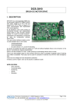
1.1 Typical Application
Shown below is a block diagram of a typical application.
Encoder
Host
MCU
Serial or
I2C or
CricketBus
GMTX
Gamoto
Gamoto
- OR Host
PC
Motor
Power
MAX
232
A PC can connect using serial COM port and a
serial level-shifter, such as the Maxim MAX232
2. Operational Modes
The Gamoto can be operated in any of several operational modes. The mode setting can
be changed “on-the-fly,” by the host, during operation, or the power-on default mode can
be customized, allowing it to always power up in the desired mode. For details of the
actual Mode registers, see section xx. The various modes are outlined below.
2.1 Position Mode
Mode Register = 00000001 (0x01)
This is the default mode, in which the motor drives to the set position (stored in the
setPosition register). On power-up, the setPosition is 0, and actual position (mPosition) is
0, so the motor will not move. However, if it is disturbed or pushed one way, it will drive to
return to the target position. The PID algorithm (see Theory of Operation section)
determines the power sent to the motor. In the windows control software, there is an
interactive mode that demonstrates position control based on mouse movements.
2.2 Power Mode
Mode Register = 00010001 (0x11)
Enabled by setting PwrMode bit of Mode register. This mode is the simplest to use and to
understand. In this mode, a raw motor power number is sent to the Gamoto, as a
percentage of power desired to send to the motor. This register, mPower, is a signed 8-bit
number, and can range from –128 to +127. (0 = 0% power, 127 = 100% forward, -128 =
100% backwards). In this mode the encoders are ignored, so in fact encoders are not
necessary. However, if encoders are connected, then the current position and velocity can
be read from the internal registers while the motor is running.
2.3 Velocity Mode
Mode Register = 0000101 (0x05)
Enabled by setting the VelMode bit of the Mode register. This mode allows easy control of
2005 Gamatronix
Page 7 of 45
Gamoto
Gamoto
motor velocity, while still tracking the absolute position. When this mode is set, the value in
register SetVelocity is used as a velocity target. Setting SetVelocity = 0 causes the motor
to stop. SetVelocity is a signed 16-bit register, and the lowest 8 bits are fractional. The
actual value to use for a given velocity depends upon your encoder resolution, so this must
be found by trial and error.
The actual algorithm for this mode is as follows: SetVelocity is added to the target
setPosition register every control cycle. This means the target position is always changing,
but at a constant rate, leading to a constant average velocity. Be aware that if the motor is
slowed by an obstacle, and then freed, it may temporarily speed up to “catch up” to the
moving position target. This leads to an accurate average velocity, but not always the most
stable instantaneous velocity.
2.4 Trajectory Mode
Mode Register = 0000011 (0x03)
Enabled by setting the TrajMode bit of the Mode register. This mode causes the Gamoto
to immediately begin following the pre-set trajectory that has been stored in the trajectory
registers.
2.4.1 Trajectory Stop
Mode Register = 0001011 (0x0B)
Enabled by setting the StopGrace bit of the Mode register, this allows the host to
prematurely stop a trajectory in progress, but rather than suddenly stopping the motor, the
motor is gracefully decelerated at the rate specified by the original trajectory. This is useful
when the distance to travel is not known ahead of time, or an event triggers a necessary,
but not urgent, stop. Note this requires Trajectory Mode to be enabled, and Velocity Mode
disabled. If there is no trajectory currently active, setting this mode will have no effect.
2.5 Homing Mode
Mode2 Register = 00000001 (0x01)
This mode is normally disabled. Enabled by setting bit 0 of the Mode2 register, this mode
allows an external home switch to clear the position register and stop the motor
automatically. It changes two of the analog pins to digital pins (Analog pins 2 and 4), and
uses Analog channel 4 (Connector J1, pin A4) as a home switch input. Normally high (you
need to supply a pull-up resistor of 1K-50K), when pulled low while in Velocity mode, the
position registers are cleared, Velocity is set to 0, and the mode will change to Position
mode, stopping the motor.
The second converted digital channel, A2, is not used for this homing feature, and will still
read analog values, even though it is configured as a digital pin.
2.6 MotionDone Enable
Mode2 Register = 00000010 (0x02)
This option is normally disabled. Enabled by setting bit 1 of the Mode2 register, this option
turns one of the analog pins (A2) into an output, and uses it to signal when a motion profile
has been completed (A2 goes high). This can be used as an interrupt to an external MCU
or other control system, in place of polling the Mode register to detect when a motion is
2005 Gamatronix
Page 8 of 45
Gamoto
Gamoto
complete. As with the Homing mode, pin A4 becomes a digital pin, but is still able to read
analog input voltages.
2.7 SerialShare Enable
Mode2 Register = 00000100 (0x04)
This option is normally disabled. It allows you to connect up to 8 Gamotos to the same
serial TX and RX lines, with no additional hardware other than a 10K pull-up resistor, which
may be needed in some cases. When this bit is set, the Gamoto allows the TX line to float
when it's not being used. Since each Gamoto only replies to messages addressed to it (by
the correct header/DIP switch combination), then only the proper Gamoto will reply. Since
the TX line is floating when not in use, a 10K pull-up resistor is recommend, if not already
included in your serial transceiver or MCU.
2.8 115200 Baud Rate
Mode2 Register = 00001000 (0x08)
This option enables serial communication at 115200 baud, regardless of the dip switch
settings for baud rate (9600/19200). Note that if you set this mode bit via a serial
command, the response will come back at the current baud rate – it will not change to
115200 until you reset the Gamoto, either manually or with a reset command.
2.9 Step + Direction Pulse Inputs
Mode2 Register = 00010000 (0x10)
This option enables command of the motor via Step and Direction signals, similar to a
stepper motor driver. This allows you to use existing stepper motor driver software, for
example in CNC applications, to control your DC servo motor. The Step signal connects to
J4 Pin 2 (Normally the Lower Limit switch input) and the Direction signal connects to J4 pin
3 (Normally the Upper Limit switch input). The limit switches are of course disabled while
in this mode.
If the Direction signal is high, then each rising edge of the Step signal will jog the motor one
count forward (setPosition gets incremented). If the direction signal is low, the setPosition
register gets decremented.
StepSize Register (Address = 0xB3, or 179 decimal)
If you want each step pulse to jog more than one count, use the StepSize register to set
the step size to something larger than 1. For example, if StepSize = 10, then each
incoming step pulse will jog the motor to (mPosition + 10).
2.10 Analog Feedback Mode
Mode2 Register = 00100000 (0x20)
This mode allows Analog Channel 1 to be used as the position feedback, rather than
quadrature encoder signals. This makes it easier to convert a simple motor to a servo,
without the need for a costly quadrature encoder. The 0-1023 signal is fed directly to the
mPosition register, and the encoder inputs are ignored.
2005 Gamatronix
Page 9 of 45
Gamoto
Gamoto
2.11 R/C Pulse Input Mode
Mode2 Register = 01000000 (0x40)
This mode allows the Gamoto to accept standard R/C (Remote Control) input pulses to
command the motor set point. These R/C pulses are generally in the range of 1ms – 2ms
wide pulses, repeated every 20ms. The Gamoto accepts any pulse in the range of 0.2ms
to 3ms, and the repeat rate is not important.
To configure the low and high pulse range and low and high desired set points, use the
MotoView R//C Pulse configuration dialog, under the Tools menu. This dialog also shows
the real-time pulse width being received, so it's handy for debugging your R/C equipment.
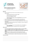
T1
T2
T3
R/C Pulse Timing Requirements:
T1: Minimum pulse width is 0.2ms. Any smaller pulses will be rejected as noise.
T2: Normal pulse range is 0.2ms to 3.0ms. Max and min are settable via MotoView.
T3: Time between pulses must be at least 20 usec (0.020ms). There is no maximum. If the
signal is lost, the set point will remain at the set point given by the last valid signal.
Note that in the current firmware version, when using R/C Pulse mode, you must
also enable Analog Feedback mode.
To set up this feature, you need to set the following key parameters: RCPmin, RCPmax,
SPmin, and SPmax. These parameters are described by the diagram below. Any R/C
Pulse that is shorter than the RCPmin value (but greater than 0.2ms) will be result in a set
point of SPmin. Similarly, a pulse larger than RCPmax will result in a set point of SPmax.
If we take an example, let’s say you connect your R/C radio receiver to the Gamoto, open
2005 Gamatronix
Page 10 of 45
Gamoto
Gamoto
the MotoView R/C config dialog, and look at the Raw R/C pulse counts. If you’re getting
values from say 4412 to 9762, then you could set RCPmin to 4500, and RCmax to 9700.
Values outside of this range will get clipped to the max and min values.
Now you need to look at your potentiometer, and see what values you get for feedback. If
your analog1 channel is showing values from 8 to 1019, then you could set SPmin to 10
and SPmax to 1015. You wouldn’t want to set the min/max values outside of your actual
range, or else you could reach the mechanical limit of your motor motion, and the motor
would still be trying to drive.
2.12 PWM Modes
There are two available modes for controlling the power to the motor. Both use Pulse
Width Modulation (PWM), which is a digital way of delivering a range of power to a device.
Depending upon the motor design and application, it may be desirable to use one mode
over another.
2.12.1 Sign-Magnitude
Sign-Magnitude is the default mode. This method requires that two signals be sent to the
H-bridge: direction (Sign), and Magnitude. The Magnitude is always positive, and the
direction changes depending on which way the motor is to be driven.
The Magnitude signal is a square wave with a fixed base frequency of 19.2 kHz, and
varying duty cycle, from 0 to 100%, corresponding to 0 and 100% power delivered to the
motor.
The Sign, or direction signal, is a digital high for clockwise rotation, and low for counterclockwise motion.
2.12.2 Locked Anti-Phase
To enable Locked Anti-Phase (LAP) mode, set the LAP PWM bit in the Mode byte. Any
time you change this bit, you need to save to Flash, then power cycle before it takes effect.
In LAP mode, direction and magnitude are combined into one signal. The “zero power”
condition is represented by a 50% duty cycle. Full forward is 100% duty cycle, and full
backward is 0% duty cycle. The reason for this behavior is that this pin is connected to the
Direction input of the H-bridge, so that at 50% power, the motor is actually reversing
direction constantly, which averages out to zero net power.
The other pin on the H-bridge that is normally used for PWM input is now used to enable or
disable the motor.
The advantages and disadvantages of these PWM modes have been much debated in the
motor control community. If you don’t have an opinion, use the default Sign Magnitude
mode. If you have a very free-spinning motor and would like more of a braking effect when
slow or stopped, then you should try LAP mode.
3. Braking behavior
The LMD18200 Dual H-Bridge chip has a braking feature that, in the case of the Gamoto,
is controlled by one bit (the “Brake” bit) in the Mode byte. When the Brake bit is set, the
Brake pin on the bridge goes high. When the Brake bit is clear, the Brake pin goes low.
The first confusing point is that this type of “braking” usually does not stop a motor, and is
sometimes a barely noticeable effect. It works by effectively shorting the motor coil leads
2005 Gamatronix
Page 11 of 45
Gamoto
Gamoto
together. With some motors this causes a strong resistance to spinning, and other motors
just seem sluggish. It’s best to think of it as a way to reduce the amount of “coasting” or
free-wheeling after a controlled move.
The second confusing part of the braking behavior is the way that the H-Bridge has
implemented the brake. The data sheet states that to assert the brake, you not only need
to set the Brake pin high, but also set the PWM input high. The PWM input normally tells
the motor to turn on! So in the case of the Gamoto, you would need to turn on the Brake
bit of the Mode byte, then command the motor to go at full power (set PwrMode of Mode
byte, then set mPower=127), in order to activate the brake. This actually works – the motor
does not turn, and has a noticeable resistance to turning in this condition. But there is a
better way.
The third confusing part of the behavior actually allows a more convenient way to use the
brake. According to the H-bridge datasheet, if the brake pin is Low (disabled) while the
PWM pin is low (no command for power), then the braking is actually ON. This means that
during normal operation, when you signal zero power to the motor, the braking is activated.
This actually makes sense, because if you want zero power, you generally want to stop. If,
for some reason, you want to stop and coast, then you ask for zero power, and then turn
ON the Brake bit. Note that as long as the Brake bit is on, it cannot be controlled by the
Gamoto, so if it slips away from its setPosition, it will not drive back to set point until the
Brake bit is turned off.
Bottom line: Don’t worry about the Brake. For most cases, you won’t ever need to set it or
read it or understand it. The one exception is the case where you really want to free-spin
your motor with no power. In this case, send zero power and turn on the brake bit.
4. Theory of Operation
The Gamoto motor controller uses a PID (Proportional, Integral, and Derivative) algorithm
to calculate how much power to deliver to the motor, and in which direction. This is not a
new technique. It was developed in the 1960’s, and is still the accepted standard today for
fast, accurate motion control, as well as most other types of control systems.
The main equation has three major components, the sum of which equals the power to be
delivered to the motor. The inputs to the equation are the set point (“setPosition” register),
the actual position (“mPosition” register), and the three key constants, Kp, Ki, and Kd, the
proportional, integral, and derivative constants, respectively.
We can calculate the error, “u,” by subtracting the set point from the actual position:
(1)
u = mPosition – setPosition
The Proportional component is straightforward:
(2)
Kp
u
The Integral component is calculated based on the integral over time of the error:
(3)
Ki
udt
The Derivative component is calculated based on the differential the actual position over
time, which in the case of motor control, is the same as the velocity (“mVelocity” register):
(4)
2005 Gamatronix
Kd
mVelocity
Page 12 of 45
Gamoto
Gamoto
So the resulting equation is:
mPower = Kp
u + Ki
udt + Kd
mVelocity
One more final scaling is performed, to allow the use of motors that cannot handle the full
voltage of the power supply. For example, if you are using a six volt motor with a 12 Volt
battery, you can set pwrLimit = 50% power, or 127. The final equation then, is:
mPower = [ Kp
u + Ki
udt + Kd
mVelocity ]
[ pwrLimit / 255 ]
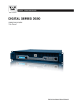
4.1 Trajectory Control
As mentioned in the velocity mode section, velocity is controlled by continuously adding to
the position set point. In the same manner, adding to the velocity set point can cause a
constant acceleration. These techniques are combined, along with distance planning and
deceleration, to create a Trajectory Move. The diagram below shows a normal trajectory
move.
v
Velocity, v
Acceleration, a
-a
Distance, x
x
Given a desired distance, velocity, and acceleration, a move can be completed smoothly
and accurately. You can create and test these trajectories easily, using MotoView. Once
you decide a few trajectories that you will use in your application, you can store up to
seven of them in flash. Or you can create them and run them on the fly.
To run a trajectory, the following steps are necessary:
Write to the desired X, V, and A trajectory registers
Write the corresponding trajectory number to the TrajNum register
Set Mode to 0x03 to run the trajectory
To determine when it’s complete, you can poll the Trajectory Mode bit in the Mode byte.
Or you can turn on MotionDone Enable (by setting Mode2, bit 1), and monitor pin A2
(on J1). This pin is normally low, and will go high when the motion is complete.
The distance value is always a relative distance, to be added to the current position.
When using trajectories, it’s a good idea to follow these guidelines:
For negative moves, use a negative x or negative v, but never use a negative
acceleration.
v/a should be an integer, especially for large values of v and/or a. For example, if
v=5000 and a=1000, then after 5 cycles, v will become 5000, and will stop increasing.
But if a=1100, then after 4 cycles, it will be 4400, and after 5 cycles, will overshoot to
2005 Gamatronix
Page 13 of 45
Gamoto
Gamoto
5500, and then stop increasing. In the extreme case of v close to the maximum value
(32767) and large values of a, then the velocity can roll over to a negative value.
If the maximum v is not fast enough, decrease dS.
If the minimum v is not slow enough, increase dS.
Reminder: Changing dS will also affect the strength of the Kd term, in a linear fashion.
Maximum values for trajectory variables:
Var
x
v
a
Length
3 bytes, signed integer
2 bytes, signed integer
2 bytes, signed integer
Range
-8388608 to 8388607
-32768 to 32767
0 to 32767
Special case: Short Trajectory
In the event that the distance specified is short, and acceleration is small, then the velocity
may never be achieved. This is not a problem for the Gamoto, but it is good to be aware of
this possibility. A diagram showing this situation is shown here:
v
Target
Velocity, v
a
x
x
Detecting the end of the trajectory:
This diagram shows a trajectory move, and how the Mode byte changes and the
MotionDone pin signals the end of the trajectory, if MotionDone is enabled in the Mode2
byte:
Motor Speed
Pin A2, J1
“MotionDone” pin
Mode Byte
Mode=1
Mode=3
Mode=1
NOTE: It’s important to note that by “Trajectory Done” it means that the position setpoint
(setPosition) has reached its target value, not that the actual position has reached the
2005 Gamatronix
Page 14 of 45
Gamoto
Gamoto
target value. There are several reasons for this. The main reason is that there is no good
way to tell if the position has been reached, i.e. what if it reaches it briefly, but then
overshoots the position? What if it comes close, but due to the P,I,D settings, there is
some steady-state error? How long should it "settle" at the destination before declaring it
has arrived? If it never reaches, what should the timeout behavior be? All of these
questions will have very different answers depending on the application, so we have left it
to the user to decide. The idea is the user would implement this kind of use case:
Distance is set to 10000 (default)
Velocity is set to 5000 (default)
Acc set to 10 (default)
TrajMode is set to 1
SetPosition increases
Host program polls "Trajectory Done" bit, until it changes to 0 (now we know
setPosition = 10000)
Host position polls "Error" register (u0) until Error = 0, or |Error| < AcceptableLevel
<insert timeout behavior, acceptable level window, etc. logic in this step>
Now we know we have arrived at the destination
4.2 Units of Measurement
The units used to control and calculate the position, velocity, and acceleration are different
than typical “real-world” units. To aid in the conversion to meaningful units, this section
describes how to do the conversions.
Some basic definitions:
CPR = Counts per revolution (counts/rev). This is how many encoder counts for every
complete revolution of your output shaft or wheel. To measure this value, run MotoView
and show the Register View window. Display mPosition. Turn your output shaft one turn,
and note how many counts have passed.
ORD = One Revolution Distance (inches/rev, feet/rev, etc.). This is the distance your
device moves in one revolution, in the distance units of your choice. In the case of a
wheel, it's the circumference of the wheel.
To = Period of Gamoto PID loop. This is a fixed constant, equal to 0.00051 seconds.
dS = Number of PID cycles to skip when updating velocity, Kd, and profile information. The
factory default value is 10, but this is changeable by the user.
V = Velocity. This can be represented in many units, as shown below. The basic unit is
the internal Gamoto units, which are in relation to the PID loop of the Gamoto.
2005 Gamatronix
Page 15 of 45
Gamoto
Gamoto
4.2.1 Velocity Equations
V
V (counts/sec) =
256 * To * dS
V (inches/sec) = V (counts/sec) * (ORD/CPR) (assuming ORD is in inches/rev)
V (miles/hour) = (V in inches/sec) * (5/88)
Example calculation:
We have a robot with 3” diameter wheels, driven by a motor with 19:1 gear reduction. The
encoders have 250 counts/rev, and are attached to the motor, before the gear reduction.
First, the CPR of the output shaft = 250 * 19 = 4750 counts/rev.
The ORD = circumference of the wheel, or pi * D, or 3.14159*3 = 9.42 inches/rev
When using MotoView, we enter a set velocity = 8000, and dS=10. How fast is the motor
going?
V = 8000 / (256*0.00051*10) = 6127.5 counts/sec
V = V (counts/sec) * (ORD/CPR) = 6127.5 * (9.42/4750) = 12.15 inches/sec
V = (V in inches/sec) * (5/88) = 12.15 * (5/88) = 0.69 miles/hour
4.2.2 Acceleration Equations
A
A (cnts/sec2) =
2
256 * (To * dS ) 2
2
A (inches/sec ) = A (cnts/sec ) * (ORD/CPR)
2
A (relative to gravitational constant g) = A (inches/sec ) / (12 * 32.2)
Example calculation:
If we continue the above example, let's find out how fast an acceleration setting of 20 will
cause the robot to accelerate:
2
2
A (cnts/sec ) = 20 / (256 * (.00051 * 10) ) = 20 * 150.18 = 3003.65 cnts/sec
2
A (inches/sec ) = 3003.65 * (9.42 / 4750) = 5.96 inches/sec
2
2
A (relative to g) = 5.96 / (12 * 32.2) = 0.015 g
4.2.3 Example Torque Calculation
Let's assume we are powering our robot with two motors capable of 20 oz-in of torque.
What value should we use for the Gamoto acceleration setting? Assume our robot weighs
4 lbs, or 64oz.
2005 Gamatronix
Page 16 of 45
Gamoto
Gamoto
First, since we have two wheels, we have 2 x 20 = 40 oz-in of torque available. Now, the
definition of torque is force times distance:
Torque = 40 oz-in = (Force) x (Wheel Radius), so, solving for Force, F = T/r
Force = (40 oz-in) / (1.5 inches) = 26.7 oz = 1.67 lbf
So now we know the Force we want. How does this relate to acceleration?
F = ma (Newton's Law), so a = F/m
First we need to know the mass in lbm, which is equal to its weight divided by g:
m = 4 lbf = (4/32.2) = 0.124 lbm
a = (1.67 lbf) / (0.124 lbm) = 13.44 ft/ sec
2
2
a = (13.44 ft/sec ) x (12 in/ft) = 161.3 in/ sec
2
2
Now we know the acceleration in in/sec that we are shooting for. To summarize all of the
above calculations, we can use this condensed expression:
A (in/sec2) =
24.15 * T
W*r
Where T = Total Torque in oz-in, W = Weight in pounds, and r = wheel radius in inches.
Now we need to use the acceleration equations backwards to deduce what we should use
for our A setting.
A =
A =
A (inches/sec2) * 256 * (To * dS ) 2 * CPR
ORD
161.3 (inches/sec2) * 256 * (0.00051* 10 ) 2 * 4750
9.42
A = 542
So now we know the maximum setting possible for use in our trajectories. Setting any
value higher than this will exceed the capacity of our motors, and will result in high errors
and overshoot.
Keep in mind that when using trajectories, the velocity you choose should be an even
multiple of the acceleration. In this example, valid velocities include 5420, 8130, 11382,
etc. Any even multiple of 542, that is within the bounds of valid velocities (-32768 to
+32767).
2005 Gamatronix
Page 17 of 45
Gamoto
Gamoto
5. Internal Registers
The host controls the Gamoto by writing to and reading from various internal registers.
Each section below describes the name, address, and purpose of each internal register.
Where applicable, an R, W, or R/W is shown, indicating whether the register is Read-only,
Write-only, or Read/Write, respectively. Note that registers in locations 34 - 44 can be
changed and stored to flash, to allow different power-on conditions.
5.1 Command Registers
Almost everything you need to do to control the Gamoto can be done by reading or writing
to the internal registers. However, there are a few special cases of standalone commands,
listed below, that require different treatment. Writing to any of these registers will execute
the command. The data that is written is not important; in fact you don’t need to write any
data at all.
Any write command to these registers will activate the command.
2005 Gamatronix
Page 18 of 45
Gamoto
Gamoto
5.2 Register Memory Map
Note: All registers are stored with the LSB first, MSB at the highest address. Where noted,
some registers have a fractional component.
DEC HEX Register
0
$00 FactoryRst
1
$01 SaveParms
2
$02
Reset
3
$03
SetHome
34
$22
Kp
36
$24
Ki
38
$26
Kd
40
$28
iLimit
42
$2A
dS
43
$2B
Mode
2005 Gamatronix
Len
Description
1 Writing to this special command register will cause all key registers
(34 – 44) to be reset to factory default values. See Appendix A for
factory default values. WARNING: This command takes about 300
ms to execute. If you execute this command during a trajectory
move or while in velocity mode, you may notice a slight jerk or
hesitation in motion. It is best not to issue this command while in
velocity or trajectory mode.
1 Writing to this special command register will save all key registers to
flash. After this operation, these values will survive a power cycle.
The key registers are locations 34 – 44, and all motion trajectory
values. WARNING: This command takes about 300 ms to execute. If
you execute this command during a trajectory move or while in
velocity mode, you may notice a slight jerk or hesitation in motion. It
is best not to issue this command while in velocity or trajectory mode.
1 Writing to this special command register will reset the Gamoto, just
as if it were power-cycled. As with all command registers, any
dummy byte can be written to activate the command.
1 Writing to this special command register will set the mPosition and
setPosition registers to zero, effectively making the current position
“Home”. The current Mode is not changed.
2 Kp is the proportional constant register, used to scale the overall
response of the system. Kp is multiplied by the position error.
Signed 16-bit number. Can range from –32768 to + 32767, but
negative numbers should not be used for this register.
2 Ki is the integral constant register, used compensate for steady-state
error in the system. Ki is multiplied by the integral of the position
error. Signed 16-bit number. Can range from –32768 to + 32767,
but negative numbers should not be used for this register.
2 Kd is the derivative constant register, used to compensate for
overshoot in the system. Kd is multiplied by the derivative of the
position error. Signed 16-bit number. Can range from –32768 to +
32767.
2 iL (integration Limit) is used to limit the maximum build-up of integral
error. Prevents “integral windup” problems, when a long-lasting
steady-state error causes excessive build-up of the integral term.
Signed 16-bit number. Can range from –32768 to + 32767, but
negative numbers should not be used for this register.
1 Unsigned 8-bit number. Can range from 1 to 255. Setting this to 0
has the effect of setting dS = 256. Number of cycles over which
average velocity is calculated. For higher resolution encoders, this
number should be lower, to prevent overrun of actual motor velocity
register (mVelocity). For low resolution encoders, increase this
number. This is also used to trigger the update of the trajectory
variables. A lower number updates more often.
1 8-bit number. Each bit enables or disables various modes. For a
complete description, refer to section 3.1, Mode Register.
Page 19 of 45
Gamoto
Gamoto
44
$2C
pwrLimit
1
45
$2D
Mode2
1
47
$2F
setPosition
3
51
$33
mPosition
3
54
$36
setVelocity
2
57
$39
mVelocity
2
59
$3B
trajectory
1
60
$3C
mPower
1
90
$5A
RCPraw
2
97
$61
u0
3
178
179
$B2
$B3
version
StepSize
1
1
226
$E2
SPmin
2
228
$E4
SPmax
2
230
$E6
RCPmin
2
2005 Gamatronix
8-bit number to limit maximum power delivered to the motor. Set to 0
for zero power to motor, 127 for 50% power, and 255 for 100%
power. Normally set to 255. Use this to limit max voltage when
using a lower-voltage rated motor. For example, using a 12V battery
with a 6V motor, set this to 127, and the motor will never see more
than the equivalent of 6 volts.
8-bit number. Each bit enables or disables modes. For complete
description, see section 3.2, Mode2 Register.
24-bit signed integer. Can range from –8,388,608 to 8,388,607. This
is the target position. The error term is the difference between
setPosition and mPosition.
24-bit signed integer. Can range from –8,388,608 to 8,388,607. This
is the actual motor position. The error term is the difference between
setPosition and mPosition
16-bit signed integer, specifying desired velocity. This number,
divided by 256, is added to the target position, setPosition, every dS
th
period. For example, if dS=10, then every 10 control cycle,
setVelocity/256 is added to setPosition.
This is a signed 16-bit number that represents the actual motor
velocity, totaled over several (dS) cycles. The velocity is calculated
as the change in encoder counts in a given time period. To change
the scaling of this number, dS can be adjusted. mVelocity is also the
multiplier for Kd, used to calculate the derivative term for the control
loop, so changing dS will have a direct effect on the strength of the
derivative term.
The trajectory register is used to choose which trajectory you would
like to run. To run a given trajectory, first store the desired distance,
velocity, and acceleration in one of the 7 trajectory register sets.
Then specify which trajectory register set you want to run by writing
to trajectory. Then turn on trajectory mode by writing the proper
mode command to the Mode register.
Motor power. Signed 8-bit number. Used normally in open-loop
mode (without encoders), or when you want manual control over
actual voltage delivered to the motor. Setting mPower = 0 will cause
motor to stop. Setting mPower = 64 will cause 50% forward power.
Setting mPower = 127 will cause full forward power, setting mPower=
-128 (128) will cause full reverse power. A setting of –64 (192) will
cause 50% reverse power.
Raw R/C pulse counts. 5000 counts = 1ms. This holds the length of
the last R/C pulse received. Only used while in R/C mode.
Error term. Signed 24-bit number. This is the difference between the
target position (setPosition) and actual motor position (mPosition).
Read this value to detect if an obstacle or friction is causing a large
difference between the goal and actual position, or velocity.
Firmware version number. Integer from 1 to 255. Read only
Number of steps to “jog” when step/dir input is enabled, and Gamoto
receives a step pulse.
setPosition Minimum. This is the minimum value that will be set by an
incoming R/C pulse. Refer to the R/C mode description.
setPosition Maximum. This is the maximum value that will be set by
an incoming R/C pulse. Refer to the R/C mode description.
R/C Pulse minimum. This is the minimum pulse length accepted by
the Gamoto. Shorter lengths will be clipped to this length. The units
are in raw counts, 5000 counts = 1 ms.
Page 20 of 45
Gamoto
Gamoto
232
$E8
2005 Gamatronix
RCPmax
2
R/C Pulse maximum. This is the maximum pulse length accepted by
the Gamoto. Longer lengths will be clipped to this length. The units
are in raw counts, 5000 counts = 1 ms.
Page 21 of 45
Gamoto
Gamoto
5.3 Analog Registers
These registers are all two byte (16-bit) memory locations, but there is only 10 bits of
resolution. The data is right-justified to the LSB, that is, the LSB is the first byte, and it
contains the lower 8 bits, and the next byte contains the upper two bits of the analog value.
The upper remaining bits are padded with zeros.
Example of register mapping for Analog0 register:
MSB
<zero padding>
161 ($A1)
1
0
1
1
0
LSB
1 0 1
160 ($A0)
0
1
This table shows the addresses for all of the analog registers. Note that Analog0 is a
special case: it is tied to the motor current output signal from the H-Bridge.
DEC HEX Register
160 $A0 Analog0
Len
2
162 $A2 Analog1
2
164 $A4 Analog2
2
166 $A6 Analog3
2
168 $A8 Analog4
2
2005 Gamatronix
Description
This is wired directly to the H-Bridge, and provides a reading
proportional to Motor current. Reading translates to
approximately 186 counts / amp, with max reading of 1023
counts = 5.5 Amps
Analog input 1. Scale is 0-5V, with 10-bit resolution, making the
register minimum = 0, maximum = 1023.
Analog input 2. Scale is 0-5V, with 10-bit resolution, making the
register minimum = 0, maximum = 1023.
Analog input 3. Scale is 0-5V, with 10-bit resolution, making the
register minimum = 0, maximum = 1023.
Analog input 4. Scale is 0-5V, with 10-bit resolution, making the
register minimum = 0, maximum = 1023.
Page 22 of 45
Gamoto
Gamoto
5.4 Motion Trajectory Registers
The motion trajectory registers are shown below. The all begin with LSB first as with all
registers. The distance register is three bytes (24-bits), and the others are 2 bytes (16bits). You can store up to six motion trajectories in this memory space, and they can be
saved in non-volatile flash memory if desired (see the SaveParms command).
To calculate the address of a motion profile register (where n = 0 to 5):
X(n) = 180 + n*7
V(n) = 183 + n*7
A(n) = 185 + n*7
DEC
180
183
185
187
190
192
194
197
199
201
204
206
208
211
213
215
218
220
2005 Gamatronix
HEX
$B4
$B7
$B9
$BB
$BE
$C0
$C2
$C5
$C7
$C9
$CC
$CE
$D0
$D3
$D5
$D7
$DA
$DC
Length
3
2
2
3
2
2
3
2
2
3
2
2
3
2
2
3
2
2
Register
X0
V0
A0
X1
V1
A1
X2
V2
A2
X3
V3
A3
X4
V4
A4
X5
V5
A5
Description
Relative distance for motion trajectory
Velocity for motion trajectory
Acceleration for motion trajectory
Relative distance for motion trajectory
Velocity for motion trajectory
Acceleration for motion trajectory
Relative distance for motion trajectory
Velocity for motion trajectory
Acceleration for motion trajectory
Relative distance for motion trajectory
Velocity for motion trajectory
Acceleration for motion trajectory
Relative distance for motion trajectory
Velocity for motion trajectory
Acceleration for motion trajectory
Relative distance for motion trajectory
Velocity for motion trajectory
Acceleration for motion trajectory
Page 23 of 45
Gamoto
Gamoto
5.5 Mode Register
The mode register is shown below. It is a one-byte register, and each bit serves a different
function, as shown. Care must be taken to avoid setting incompatible bits, as not every
combination is allowed. The allowable modes and combinations are described in the
paragraphs below.
Register Name: MODE (Address 0x2B)
R/W 0
R0
LAP PWM
Over-temp
Bit 7
6
bit 7
bit 6
bit 5
bit 4
bit 3
bit 2
bit 1
bit 0
2005 Gamatronix
R/W 0
R/W 0
R/W 0
R/W 0
R/W 0
R/W 0
Brake
PwrMode
StopGrace
VelMode
TrajMode
MpwrON
5
4
3
2
1
Bit 0
Locked Anti-Phase PWM mode
1 = LAP mode
0 = Sign-Magnitude PWM mode
NOTE: To change PWM mode, you must first set/clear the bit, then save to Flash, then
power-cycle the motor controller. This only required for this particular Mode bit.
Over-temperature condition (READ-ONLY signal from H-bridge)
1 = Over-temp signal is active from H-Bridge. Motor is disabled, and setPosition is set to
mPosition, so when condition clears, motor will not jump
0 = Normal condition
Brake On
1 = Brake signal is being sent to H-Bridge
0 = Normal condition
PwrMode
0 = Power Mode is Disabled. In this state, the PID loop operates normally, and the
mPower register is ignored
1 = Power Mode is Enabled. In this state, the PID loop is bypassed, and the motor power
is taken directly from the mPower register. Encoder position is tracked but ignored.
StopGrace
0 = Disabled
1 = Enabled. When this bit is set during a trajectory move, the Gamoto immediately starts
decelerating, until completely stopped, using the deceleration rate that is stored in
the trajectory. This is only valid when TrajMode is set.
VelMode
0 = Disabled
1 = Enabled. When this bit is set, the SetVelocity register is used as a velocity set point.
Use this when you want to control the velocity, rather than absolute position. The
PID loop will continually add this value to the Position target register. This “moving
target” position value causes a constant average velocity. This is only valid when
TrajMode is disabled.
TrajMode
0 = Disabled
1 = Enabled. When this bit is set, the Gamoto immediately begins following the preloaded trajectory. When the trajectory has been completed, this bit is automatically
cleared. Poll this bit to find out when the move has been completed.
MpwrON
0 = Disabled. Motor will not receive power without this bit set.
1 = Enabled. When this bit is set, the enable pin on the H-Bridge is set, allowing power to
flow to the motor.
This bit is independent of all other mode settings.
Page 24 of 45
Gamoto
Gamoto
5.6 Mode2 Register
The Mode2 register is shown below. It is a one-byte register, and each bit serves a
different function, as shown. Care must be taken to avoid setting incompatible bits, as not
every combination is allowed. The allowable modes and combinations are described in the
paragraphs below.
Register Name: MODE2 (Address 0x2D)
R/W 0
R/W 0
R/W 0
R/W 0
R/W 0
R/W 0
R/W 0
R/W 0
reserved
R/C Pulse
Enable
Analog
Feedback
Step +
Direction
115200
baud
SerialShare
MotionDone
Homing
2
1
Bit 7
6
5
4
bit 7
Reserved for future use
bit 6
R/C Pulse Input Enable
1 = enabled
0 = disabled
bit 5
Analog Feedback Enable
1 = enabled
0 = disabled
bit 4
Step+Direction Pulse Input Enable
1 = enabled
0 = disabled
bit 3
115200 Baud Rate Enable
1 = enabled
0 = disabled
bit 2
SerialShare Enable
1 = Serial Share enabled
0 = SerialShare disabled
bit 1
MotionDone Enable
1 = enabled
0 = disabled
bit 0
Homing Mode
1 = Homing Mode enabled
0 = Homing Mode disabled
3
Bit 0
6. Communication Protocols
2
There are three ways to communicate with the Gamoto: Serial, I C bus, or Cricket Bus. All
of them require setting/checking the dipswitch settings for configuration.
2005 Gamatronix
Page 25 of 45
Gamoto
Gamoto
6.1 Dip Switch Settings
The table below shows the dip switch assignments, and the purpose of each of the
switches. Before attempting to use the Gamoto, make sure the switches are set
appropriately. The factory default position is all switches in the OFF position.
Dip Switch Assignments
Switch
1
2
3
4
5
OFF
Cricket Bus
19200 baud
0
0
0
ON
2
IC
9600 baud
1
1
1
Description
Bus selection
Serial baud rate
A2 Address bit
A1 Address bit
A0 Address bit
2
Note that the user must choose either I C or Cricket bus, because they share the same I/O
pins on the controller. The serial port uses different pins, and can be used regardless of
the bus selection position. However, it is not advisable to use the serial port while data is
2
being sent/received on the Cricket or I C bus, because some of the same internal registers
may conflict in this case.
The A0, A1, and A2 address switches are used to set the Gamoto Address to a value from
2
0 to 7. The I C, Cricket Bus, and Serial protocols use this address to determine which
2
Gamoto is being addressed. The table for setting this address is shown in the I C protocol
section.
6.2 Communication Protocols: Serial
The normal connection method for serial communications is to have one host connected to
one Gamoto.
However, the Gamoto is addressable, to allow for a multi-drop
communication connection. To connect more than one Gamoto to a single host (PC or
MCU), you can simply connect the TX lines in parallel with the other TX lines, and connect
the RX lines to the other RX lines. For more detailed instructions on this, refer to this guide
available on the Gamatronix website:
http://www.gamatronix.com/gamoto/examples/Serial%20Share%20how-to.pdf
On the protocol level, allowing multiple Gamotos requires that you specify which Gamoto
you are speaking to (Gamoto Address). This is specified by setting the dipswitches, as
2
2
with the I C and Cricket protocols. Please refer to the I C communication section to see
how to set the Gamoto Address (0-7). This Address is added to hex value $AA, and
becomes the header byte of the packet. Examples of the different types of transactions are
shown below.
For the most common case of RS-232 Serial, with only one Gamoto, simply leave the
dipswitch set to the factory positions, and use a header value of $AA.
The checksum is a single unsigned byte, and is calculated by using a simple sum of the
preceding bytes, excluding the header and the checksum byte itself. In the case of the
checksum totaling more than 255, it rolls over (wraps) as necessary. An example of the
formula in Visual Basic is: CSbyte = (byte1 + byte2 + byte3 + byte4) mod
256
2005 Gamatronix
Page 26 of 45
Gamoto
Gamoto
6.2.1 Example Write $1234 to Kp Register
R
W
Header
$AA + (0 to 7)
LEN
RegNum
Data(LSB)
Data(MSB)
CHECKSUM
$03
$22
$34
$12
<--------------------- Length --------------------->
<------------------------ CHECKSUM -------------------------------->
XX
The serial protocol is binary-coded, with a header and checksum to help ensure reliable
data transfer. The example diagram above shows a two-byte write to the Kp register. The
Header byte, which is dependent on the dipswitch setting, is followed by the RW / Length
byte. The high bit of this byte is 0 for Writes, 1 for Reads. The lower nibble indicates the
length of information to follow, excluding the Checksum byte. The next byte is the target
register address, followed by data bytes, and then a checksum. The checksum does not
include the header, or the checksum byte itself.
The number of data bytes is flexible, up to a maximum total message size of 8 bytes. This
means the maximum continuous bytes you can write to a register location is 4 bytes. This
allows you to access any register with a single transaction.
6.2.2 Example Write Response
ACK
CHECKSUM
$41
$41
The reply from the Gamoto is shown above. In place of the header is an ACK byte, which
should always be = $41. If this is different, then there was some internal error.
6.2.3 Example Read from Kp Register
Node
$AA + (0 to 7)
R
W
LEN
RegNum
NumBytes
$82
$22
$02
<-------------- Len ----------->
<------------------ Checksum -------------------->
CHECKSUM
$A6
The read is same in structure as the write, with the main difference in the high bit of the
RW/Len byte. The high bit is one, indicating a read, and the data following the register
number is the number of bytes we want to read. In this case we are requesting two bytes
back, and the result is $1234 hex.
6.2.4 Example Read Response
ACK
Data (LSB)
Data (MSB)
CHECKSUM
$41
$34
$12
<------------------- Checksum ----------------->
$87
6.3 Communication Protocols: I2C
2
2
To communicate with the Gamoto using I C, the first step is to enable I C. Turning ON
2005 Gamatronix
Page 27 of 45
Gamoto
Gamoto
2
dipswitch 1 enables this mode. It should be in the ON position for I C communication. The
next step is to set the address bits (dipswitches 3, 4, and 5). If you only have one Gamoto
controller, you can leave it at the factory setting of 000 (switches 3,4,5 all OFF). However,
2
if you plan to place more than one Gamoto on the same I C bus, it will be necessary to set
each controller to a different address.
2
2
The complete I C address is constructed from three components: the I C device type (fixed
at “1001”, with the exception of the broadcast case), the Gamoto address (set by
dipswitches 3,4,5), and the Read/Write bit (0=Write, 1=Read).
I2C Slave Address Byte
1
0
0
2
I C Device Type
1
A2
A1
A0
Gamoto Address
R/W
Read/Write
Use the following table to find the desired address. A maximum of 8 controllers can be in
2
use on the same bus, due to this I C addressing limitation. Note that the address used is
different, depending on whether you are reading or writing.
Gamoto
Gamoto
Address
Address
(Binary)
(Decimal)
OFF
OFF
OFF
000
0
OFF
OFF
ON
001
1
OFF
ON
OFF
010
2
OFF
ON
ON
011
3
ON
OFF
OFF
100
4
ON
OFF
ON
101
5
ON
ON
OFF
110
6
ON
ON
ON
111
7
All
All
All
All
Broadcast
Bold row represents the factory default configuration.
SW 3
(A2)
SW 4
(A1)
SW 5
(A0)
2
2
I C Write
Address
I C Read
Address
0x90
0x92
0x94
0x96
0x98
0x9A
0x9C
0x9E
0x00
0x91
0x93
0x95
0x97
0x99
0x9B
0x9D
0x9F
N/A
One the address byte is known (sometimes called the Slave ID), you can begin writing
2
routines to control the Gamoto over the I C bus.
The last row is the “Broadcast” address, or “General Call”, which can be used to send
commands to all Gamoto boards simultaneously. This is convenient for starting two or
motors at the same time. Keep in mind, however, that it can only be used for commands
(writing), not for reading, since you wouldn’t want two or more Gamotos responding at the
same time.
6.3.1 Example 2-byte Write to Kp register
The basic sequence for a 2-byte write to a register is as follows (shown here, setting
register Kp = 0x1234):
; I2C Example: 2-byte write to Kp register
; Written in PIC Assembly. I2C subroutines not shown.
call I2CStart
movlw SLAVEID
call I2CWrite
movlw 0x22
call I2CWrite
2005 Gamatronix
; Send control byte (W)
; RegAddress = Kp
Page 28 of 45
Gamoto
Gamoto
movlw 0x34
call I2CWrite
movlw 0x12
call I2CWrite
call I2CStop
; Low byte of data to write
; High byte of data to write
; Send I2C Stop condition
2
See Appendix B for the I C library routines. Additional bytes can be added before the stop
condition. They will be written in the next sequential memory location. There is no limit on
the quantity of bytes that can be written at one time.
6.3.2 Example 2-byte Read from Kp register
A two-byte register read is as follows:
; I2C Example: 2-byte read from Kp register
; Written in PIC Assembly. I2C subroutines not shown.
call I2CStart
movlw SLAVEID
call I2CWrite
movlw 0x22
call I2CWrite
; Send control byte (W)
; Set pointer to Kp register
call I2CRepStart
movlw SLAVEID+1
call I2CWrite
; Send control byte (R)
call I2CReadwAck
movf I2CData,w
movwf RegDataLSB
call I2CRead
movf I2CData,w
movwf RegDataMSB
call I2Cstop
; First read is with ACK
; Store LSB result
; Read without ACK signals last read
; Store MSB result
2
See Appendix B for the I C library routines. Note that the master should not ACK the last
read. This signals the end of the read operation. To perform a one-byte read, the one and
only read should not be with an ACK, since it is the last read.
6.4 Communication Protocols: Cricket Bus
Before using the Cricket Bus, make sure the bus is enabled, by checking the dip switch
settings. If you will be using more than one Gamoto on the same bus, then you also need
to set each address differently, so they don’t conflict.
The Cricket communication protocol format is shown below. All Cricket messages start with
a special 9-bit Cricket Command code. The next byte is the RW/Address byte that tells if
the operation is a Read or a Write, and includes the 3-bit unit address of that particular
Gamoto controller. The 3 bits allow for up to seven Gamotos on the same Cricket bus.
The next byte is the RegNum, or register number, that specifies which register is the target
of the read or write. In the case of a write, #Bytes to Write, and Data to be written follows.
Cricket READ format:
2005 Gamatronix
Page 29 of 45
Gamoto
Gamoto
1
CrktCMD
RW / Address
{ data1, data2, …}
RegNum
Cricket WRITE format:
1
CrktCMD
RW / Address
RegNum
#Bytes to Write
{ data1, data2, …}
6.4.1 The Cricket Command Word
1
CMD bit
0
0
1
0
0
1
Cricket “Class ID” (Always = $11 for Gamoto devices)
0
The best way to think of the Cricket Command Word is that it is always written as $100 +
$11 for the Gamoto devices. The $100 signals a command, and the $11 is the Cricket
“Class ID” that has been assigned to Gamoto devices. That’s all you need to know to use
the Gamoto with Crickets.
If you are implementing a Cricket Bus yourself, using a non-cricket controller, then you may
need to understand more of the protocol details. Please refer to the Handy Cricket website
for more details on the cricket bus.
6.4.2 RW / Address Byte
R/W
Read = 1
Write = 0
0
0
Not Used
0
0
Broad
-cast
A2
Dipswitch
3
A1
Dipswitch
4
A0
Dipswitch
5
The high bit of the RW/Address byte is set to 0 for Writing, 1 for Reading. The lower 3 bits
are set to the unit address of that particular Gamoto controller, and must match the
dipswitch settings for the unit address.
Broadcast Address
To send a command simultaneously to all Gamotos on the bus, set the broadcast bit. This
is the same as using a device address of 8, rather than the usual 0 to 7. This is convenient
for starting two motors at the same time (i.e. two wheels on a robot). Note that the
broadcast address only works for WRITE operations. Read operations would cause
conflicting responses.
6.4.3 RegNum
The register number corresponds to the starting address of the register you wish to
write/read to/from. Please note that many registers have fractional components, so you
need to pay close attention to the register map to make sure you are accessing the correct
starting point of the register.
6.4.4 Data
The data following a write command can be a maximum of four bytes. After each byte is
written, the internal pointer is incremented, allowing sequential writes to a range of register
2005 Gamatronix
Page 30 of 45
Gamoto
Gamoto
bytes. When reading using the cricket bus, a dummy data byte must be sent in order to
read each byte. So to read a three-byte register, you must send the CricketCMD byte,
RW/Address byte, RegNum, then a dummy data byte. Read the first byte. Send a second
dummy byte, then read the next byte. Send a third dummy byte, then read the final byte.
6.4.5 Cricket Logo Example: Reading and Writing Registers
Using the Handy Cricket to control the Gamoto is very easy. Below is an example of using
Cricket Logo to read and write to 8-bit Gamoto registers. The command to send a byte out
the Cricket bus is bsend, and to read a byte is bsr. Every bsr command must be followed
by a dummy data byte, which is used to trigger the read operation.
The Gamoto has been assigned the Cricket “Class ID” of 17, or $11 hex. All Gamotos
respond to the class ID. The first byte to send is the command bit ($100) + $11 = $111.
Then they look at the next byte, the “adr” or address, to see if the command is for them.
This number must match the address set by the dipswitches on the Gamoto.
; Write to an 8-bit Gamoto register
to gxSetReg8 :reg :val :adr
bsend $111
bsend :adr
bsend :reg
bsend low-byte :val
end
; Read from an 8-bit Gamoto register
to gxReadReg8 :reg :adr
bsend $111
bsend :adr + 128
bsend :reg
output bsr 1
end
A full set of Cricket library routines for controlling the Gamoto is available at the
Gamatronix web site. By pasting these routines into your Cricket program, you can be
controlling the Gamoto in no time!
2005 Gamatronix
Page 31 of 45
Gamoto
Gamoto
7. Mechanical Specifications
The dimensions of the Gamoto board mounting holes are shown in the figure below. Be
careful when mounting the board to protect the bottom of the board from contact with metal
surfaces that could short out the signals. The board itself measures 2.75 in. x 2.075 in.
The mounting holes are 0.15 inch diameter, large enough for 4-40 or 6-40 screws.
1.775 in.
2.45 in.
8. Electrical Considerations
When designing your control system, one of the first considerations is the power supply
design. In general it is desirable to separate digital control power from noisy, high-current
motor power. The Gamoto board allows this separation by having two separate
connectors. J8 is for logic power input, and J2 is for Motor power connection. However,
these supplies are isolated on the board by a voltage regulator, so it is also possible to use
one power connector for both, and tie them together using jumper JP1.
Separated power inputs
When using two separate power inputs, you can take advantage of higher motor voltages,
from 12V up to 55V for your motor. You can also shut off or disconnect motor power
without resetting the logic side of the motor board. In this configuration the logic power can
be from 7.5V to 16V DC.
Combined power inputs
To combine power inputs, install jumper JP1. With JP1 installed, only one connector (J2)
must be used to supply power. DO NOT INSTALL JP1 WITH POWER CONNECTED TO
BOTH CONNECTORS! When combining the power inputs, you are limited to a more
narrow range of allowable voltages. The acceptable range for combined power input is
12V – 16V. The advantage is a simpler cabling/connector design, and one switch can
control the whole system.
REV E BOARDS ONLY: One note about the fuse: The fuse is only connected to the J2
connector; so if you are using a single power connection, use J2, not J8. Rev F and later
boards do not have this problem.
Current Draw
The typical standby current flow of the logic circuits is 40mA without encoders connected.
Depending on the type of encoders used, this will increase to 80 to 110mA. Note that with
2005 Gamatronix
Page 32 of 45
Gamoto
Gamoto
high-current encoders and high logic voltage supply (i.e. 16VDC), the 5V regulator will get
quite warm and a heat-sink is highly recommended.
Current draw for the motor side of the circuit is entirely dependent on the motor coil
resistance and the torque applied on the motor shaft. An easy way to estimate current is to
measure the motor winding resistance, and divide this into the motor voltage you plan to
use. Make sure the estimated current is less than 3 Amps before connecting it to the
Gamoto.
An example calculation is as follows: Motor winding resistance measures 6 ohms, and you
plan to use a 12V battery. Since batteries usually charge higher than their nominal voltage,
let’s assume 13 volts for the calculation. So current = 13 / 6 = 2.17 Amps. This is less
than 3 A, so it should work fine with the Gamoto.
9. Connector Pinouts
This section shows connector pin assignments and electrical details required for interfacing
the Gamoto to your application. The connectors are labeled JP1 to JP10, as printed on the
PC board’s silkscreen.
9.1 LED Indicators
The Gamoto board has three LED indicators. A green power LED (D4) lights when logic
power is present. A yellow Over-Temp LED (D3) lights when the H-Bridge indicates it is in
temperature shutdown mode. A red “Fuse Blown” LED (D2) lights when the fuse is
removed or blown.
2005 Gamatronix
Page 33 of 45
Gamoto
Gamoto
9.2 Fuses
There is one removable fuse on the Gamoto, labeled FS1, in the upper right corner of the
board. If this fuse is damaged or removed, the red fuse LED will light. The Gamoto ships
with 5A fuse in this position, but you can change this value if you like. The ordering
information for additional fuses is shown here:
Fuse Type
1.0 Amp, Fast-acting
1.25 Amp, Fast-acting
1.6 Amp, Fast-acting
2.0 Amp, Fast-acting
2.5 Amp, Fast-acting
3.15 Amp, Fast-acting
4.0 Amp, Fast-acting
5.0 Amp, Fast-acting
Digikey P/N
WK3048BK-ND
WK3050BK-ND
WK3053BK-ND
WK3057BK-ND
WK3058BK-ND
WK3024BK-ND
WK3062BK-ND
WK3063BK-ND
9.3 Jumpers
9.3.1 JP1 Motor Power Jumper
This jumper bridges the Motor Power supply with the Logic Power supply. See section 8
(Electrical Considerations) for details and precautions about using this jumper.
9.3.2 JP2 Cricket Power jumper
This jumper bridges the logic power for the Gamoto to the power on the Handy Cricket, if
you have a Cricket connected to the cricket cable. This allows you to use either only the
Handy Cricket’s power supply, or only the Gamoto power supply. Care should be take not
to use the jumper when both supplies are present.
9.3.3 JP3 Encoder 1X/4X Setting (Rev F and later boards only)
This jumper selects between 1X and 4X encoding for the quadrature encoders. A setting
of 4X allows a 500 count encoder to have 2000 pulses per revolution, by triggering on the
pulse edges, rather than each complete pulse cycle. This feature is only available on rev F
and later boards.
9.4 J1: Analog Inputs
J1
G
V+
A
Row
1
2
3
Analog Inputs
Ground
5 VDC output. Can be used to supply power to external sensor.
Analog voltage input, 0 – 5VDC
This connector is used to connect up to four analog inputs. For each of the four channels
(A1 – A4), a separate power and ground pin is available, making it easy to keep cabling
simple, and to provide power to an analog sensor, such as the Sharp GP2D12 sensor.
NOTE: Analog Channel 4 (pin A4) can be used to connect a Home Switch, if the Homing
mode is enabled (see Homing Mode description).
2005 Gamatronix
Page 34 of 45
Gamoto
Gamoto
NOTE: Analog Channel 2 (pin A2) can be used as an interrupt output, or “MotionDone” pin,
if this is enabled by configuring Mode2. In this case, it becomes a normally high output pin,
and goes low during a trajectory and high when a trajectory is finished.
NOTE: Analog Channel 1 connector can be used for the Analog Feedback feature. This
allows the use of a potentiometer or analog voltage in place of a quadrature encoder.
NOTE: Analog Channel 0 is not available on this connector, because it is dedicated to
reading motor current. It is connected to the H-bridge on the Gamoto board.
9.5 J2: Motor Power Input and Output
J2
M+
MV+
G
Pin
1
2
3
4
Motor Power Input. This supplies power for the Motor.
Output to Motor winding. Reverse these to change motor direction
Output to Motor winding. Reverse these to change motor direction
+12 – 55 VDC* input. Current consumption up to 3A continuous, 6A peak
Ground
* Maximum motor input voltage will be limited to 16 volts if jumper JP1 is used, tying
together the logic and motor voltage inputs
This connector is used both to supply motor power and to distribute power to the motor. G
and V+ should be connected to a battery or other high-current voltage source. Pins M+
and M- should be connected to the motor windings. The polarity of these terminals is
usually determined by trial and error. If the motor operates in the wrong direction, reverse
these leads.
IMPORTANT NOTE: MOTOR POWER MUST BE AT LEAST 12 VOLTS FOR THE HBRIDGE TO WORK PROPERLY. LOWER VOLTAGES WILL CAUSE STRANGE
BEHAVIOR THAT IS DIFFICULT TO TROUBLESHOOT, SO ALWAYS CONFIRM
MOTOR VOLTAGE IN CASE OF ODD BEHAVIOR.
If you do not want to use 12V or more because your motor is rated for a lower voltage, then
refer to the register descriptions on pwrLimit. This will allow you to use a lower voltage
motor.
9.6 J3: Cricket Bus connector
J3
G
Vcc
Bus
V+
2005 Gamatronix
Pin
1
2
3
4
Cricket Bus Connector.
Ground
Regulated 5VDC power supply. Use jumper JP 12 to disconnect this
Bus data line. This is normally high, low when active, or during init signal
Unregulated voltage supply
Page 35 of 45
Gamoto
Gamoto
This port can used to connect the Gamoto to a Handy Cricket or other Cricket Bus-enabled
device. A second optional “pigtail” connector is hooked in parallel to this one, for easy
daisy-chaining of bus devices. For more details on the Cricket Bus connector and protocol,
see http://www.handyboard.com/cricket/tech/bus.shtml
9.7 J4: Limit Switch Inputs and Reset
J4
G
LL
UL
Reset
Pin
1
2
3
4
Limit Switch Inputs and Reset line
Ground
Lower Limit switch input / Step signal input
Upper Limit switch input / Direction signal input / R/C pulse input
Reset line for Gamoto processor. Momentarily pull this line low to reset
Gamoto.
This connector is used to add limit-switch interlocks to your control system. By pulling the
Lower Limit input low, clockwise motion of the motor will be disabled; until the line is
released (there is an internal pull-up resistor in the Gamoto). If the Upper Limit input is
pulled low, counter-clockwise motion will be disabled, until the line is released. This allows
a mechanism of preventing travel beyond a mechanical limit, by adding limit switches at
each end of the travel.
When in Step + Direction mode, pins 2 and 3 are used for Step + Direction, respectively.
When in R/C Pulse mode, pin 3 is used for the R/C pulse input, which allows connection of
the standard R/C cable pin-out (Gnd, 5V, signal) on pins 1,2,3. Connecting +5V to pin 2 is
not needed, but has no ill effect, and is convenient for this mode of operation (see warning
below).
NOTE: When connecting an R/C signal cable to J4, remember that all
pins have a 5V maximum. If your servo cable carries more than 5V on
the middle pin (pin 2, LL), it will damage the Gamoto, so you must not
connect this pin. In this case it would be better to remove the pin or
wire for this signal, and connect only GND and the 5V R/C pulse
signal.
There is also a reset pin available to allow an external processor to electrically reset the
Gamoto, by pulling the reset line low momentarily.
2005 Gamatronix
Page 36 of 45
Gamoto
Gamoto
9.8 J5: Serial Interface
J5
1
2
3
4
Pin
G
Vreg
RX
TX
Serial Interface connector.
Signal Ground
Regulated 5 Volt supply output, available to power a serial level adapter
Serial Receive line, 5V logic levels
Serial Transmit line, 5V logic levels
This connector is used for controlling the Gamoto from a serial host, such as a
microcontroller (MCU) or PC. When communicating using this port, use the serial protocol
as described in communication section of this manual. NOTE: You cannot directly connect
a PC serial port to this connector, because the logic levels are 5V levels, not RS-232 or
RS-485 levels. A serial transceiver chip, such as the Maxim MAX232 must be used in this
case. Either RS-232 or RS-485 transceivers may be used, depending on the application. If
RS-485 is chosen, you must use a transceiver capable of automatically enabling the driver
upon transmission (“AutoDirection” feature or similar name). Two examples of this type of
chip are the Maxim MAX13487E and MAX13488E devices. See the Gamatronix website
(www.gamatronix.com) for sources for off-the-shelf serial adapter cables, to allow easy
connection to a PC.
9.9 J6: Encoder Inputs
J6
G
Vreg
A
B
Pin
1
2
3
4
Quadrature Encoder inputs
Ground
Regulated 5 VDC output. Supplies power to LED for encoder.
Quadrature Encoder input signal, Phase A
Quadrature Encoder input signal, Phase B
This connector is used to power the encoders and to receive the encoder input signals.
The two inputs, A and B, should be out of phase with each other, to indicate motor
direction, as shown below:
Encoder A
Encoder B
Please note that if a normal LED is connected directly to this power supply, a currentlimiting resistor must be used, to avoid damaging the LED. Most commercial encoder
modules have these resistors included, and some LEDs have current limiting built in.
Check the encoder or LED datasheet to be sure.
9.10 J7: I2C Interface
J7
SDA
2005 Gamatronix
Pins
1,2
2
I C Communication Interface
2
I C Data signal. This is an open-collector 5V logic signal, with pull-up
resistor.
Page 37 of 45
Gamoto
Gamoto
CLK
3,4
G
5,6
2
I C Clock signal. This is an open-collector 5V logic signal, with pull-up
resistor.
Ground
2
This connector is used to control the Gamoto from an I C Master device, such as a
microcontroller (MCU). The clock (CLK) and data (SDA) lines are held high by pull-up
resistors on the board, and are pulled low when active. Note that the two connectors are
2
wired in parallel, for easy daisy-chaining of I C devices.
2005 Gamatronix
Page 38 of 45
Gamoto
Gamoto
9.11 J8: Logic Power Input
J8
G
V
G
Pin
1
2
3
Logic Power Input. This supplies power for the digital components.
Ground
+7.5 – 16 VDC. Typical current consumption is 40 mA @ 12V
Ground
Although this is a three-position connector, only one ground connection is necessary. The
third pin has been added to help prevent accidentally reversing the input power. We
recommend using a three-pin connector for power, because it allows the user to connect in
either orientation without risk of damaging the board. WARNING: There is NO internal
protection against reverse-polarity, so if power is connected backwards, the 5V
regulator WILL be permanently damaged. The good news is that this is a commonly
available part, and not too difficult to replace if you have a solder iron and some electronic
experience. The Digikey part number is LM340T-5.0-ND, but many substitutes can be
used, such as the LM7805.
2005 Gamatronix
Page 39 of 45
Gamoto
Gamoto
10. Schematic Diagram
2005 Gamatronix
Page 40 of 45
Gamoto
Gamoto
11. Appendix A: Factory Default values
Below are the factory defaults of the flash registers. These values can be restored at any
time by writing to the command register, FactoryRst.
Register
Kp
Ki
Kd
iLimit
dS
Mode
pwrLimit
Mode2
Factory Default Value
500
3
200
5000
10
1
255
0
To change the value that these registers will have at power-up, simply set them to the
desired values, and then write to the command register SaveParms to save them to flash
memory. Now, every time you power up, the values you programmed will be set. To revert
back to the original factory values at any time, write to the FactoryRst command register.
2005 Gamatronix
Page 41 of 45
Gamoto
Gamoto
12. Appendix B: I2C Subroutines for PIC Assembly
2
The following routines can be used with a PIC microcontroller to implement an I C Master.
The sample code is for a 20MHz clock, but can easily be adapted to other clock speeds.
2
Note that for communicating with the Gamoto, 400 kHz is the maximum I C speed that
should be used.
;Slave address of I2C device to whom we are talking
#DEFINE SLAVEID 0x90
; Set this for your device
; *********************************************************************
; MACRO DEFINITIONS
; Generic PIC Assembly macro definitions
;
ifpos
macro arg1
btfss arg1,7
;Test if argument is positive (high bit clear)
endm
ifneg
macro arg1
btfsc arg1,7
;Test if argument is negative (high bit set)
endm
bank0
macro
bcf STATUS,RP1
bcf STATUS,RP0
endm
bank1
macro
bcf STATUS,RP1
bsf STATUS,RP0
endm
bank2
macro
bsf STATUS,RP1
bcf STATUS,RP0
endm
bank3
macro
bsf STATUS,RP1
bsf STATUS,RP0
endm
;
;==============================================
; I2C Routines (using H/W I2C Peripheral)
;==============================================
I2CInit:
;NOTE: I2C Pins must already be set to be INPUTS
movlw 0x28
; Set mode to I2C Master, enable I2C
movwf SSPCON
bank1
clrf SSPCON2^0x80
; Clear status flags
movlw 49
; Set speed to 100kHz w/20MHz clock
movwf SSPADD^0x80
bsf SSPSTAT^0x80,SMP
; Disable slew rate control, set for 100kHz
bcf SSPSTAT^0x80,CKE
; Set levels to I2C (set if you want SMBus
levels)
bank0
bcf PIR1,SSPIF
; Clear SSPIF interrupt flag
bcf PIR2,BCLIF
; Clear bus collision flag
return
2005 Gamatronix
Page 42 of 45
Gamoto
Gamoto
I2CWaitForIdle:
bank1
I2C_WFI:
movf SSPCON2^0x80,W
andlw 0x1F
skipz
goto I2C_WFI
ifset SSPSTAT^0x80,R_W
goto $ - 1
bank0
return
I2CStart:
call I2CWaitForIdle
bank1
bsf SSPCON2^0x80,SEN
bank0
return
I2CRepStart:
call I2CWaitForIdle
bank1
bsf SSPCON2^0x80,RSEN
bank0
return
I2CStop:
call I2CWaitForIdle
bank1
bsf SSPCON2^0x80,PEN
bank0
return
I2CRead:
call I2CWaitForIdle
bank1
bsf SSPCON2^0x80,RCEN
bank0
call I2CWaitForIdle
movf SSPBUF,W
movwf I2CData
call I2CWaitForIdle
bank1
bsf SSPCON2^0x80,ACKDT
require it)
bsf SSPCON2^0x80,ACKEN
bank0
return
; Check all busy bits
; Initiate Start
; Initiate Repeated Start
; Initiate stop
; Initiate receive
;
Don't
send
an
ACK
(EEPROM
doesn't
; Initiate ACK sequence
I2CReadwAck:
; Same as I2CRead, but we send an ACK this time
call I2CWaitForIdle
bank1
bsf SSPCON2^0x80,RCEN
; Initiate receive
bank0
call I2CWaitForIdle
movf SSPBUF,W
movwf I2CData
call I2CWaitForIdle
bank1
bcf SSPCON2^0x80,ACKDT
; Send an ACK this time
bsf SSPCON2^0x80,ACKEN
; Initiate ACK sequence
2005 Gamatronix
Page 43 of 45
Gamoto
Gamoto
bank0
return
I2CWrite:
movwf I2CData
; Save input value
call I2CWaitForIdle
movf I2CData,W
movwf SSPBUF
call I2CWaitForIdle
; Can capture ACK return value here (in SSPCON2, ACKSTAT) if desired
return
2005 Gamatronix
Page 44 of 45
Gamoto
Gamoto
13. Appendix C: FAQs
Frequently Asked Questions
1. What if my motor doesn’t have encoders, or I don’t want to use encoders?
No problem. Set the mode to Power mode, and use the mPower register to manually
control power to the motor.
2. I want to use a 6-volt motor, but the spec sheet says minimum 12 volts. Am I out
of luck?
No! Just set the max power to 50%, and there will never be more than 6V of power to
your motor, even though you are running off a 12 Volt battery. Similar power limiting
can be done for any combination of battery levels and motor limitations.
3. My Gamoto was working fine, but now the motors won’t run. What’s wrong?
Most likely your battery has run down to less than 12 Volts. Double check the voltage
and make sure it reads at least 12V under load.
4. My Gamoto board is dead. The green power light does not light when power is
connected. What’s wrong?
Most likely, the 5V regulator has been damaged, either by reversed polarity or a short
of some kind. Replace the 5V regulator.
5. Is the Gamoto firmware field-upgradeable?
Yes, it is. Please contact us at [email protected] for details to upgrade your
Gamoto firmware.
6. A red LED is lit on the board. My Gamoto is communicating, but the motors are
dead. I’ve checked the voltage levels and they’re fine. What’s wrong?
Your fuse has blown or is missing. Remove and check it for continuity. See the
section in the User’s Manual on fuses to find ordering information.
7. Where can I ask more questions, and share experiences with other users?
Join the Gamatronix Yahoo forum. The web page is at:
http://groups.yahoo.com/group/gamatronix
2005 Gamatronix
Page 45 of 45
Gamoto