1
KIFT – Autonomous Vehicle
2009
Robert Dumbaugh
Artiom Bell
Koltan Riley II
Senior Design II
Fall 2009-Group 7
i
Contents
1.0
Executive Summary...................................................................................................................... 1
2.0
Initial Technical Content............................................................................................................... 3
2.1
Enhancing Existing Systems .......................................................................................................... 3
2.2 Project Goals ................................................................................................................................... 3
2.3
Project Milestones ....................................................................................................................... 4
2.4
Evaluation Criteria ....................................................................................................................... 7
Chapter 3: Research .............................................................................................................................. 9
3.1
Introduction ................................................................................................................................. 9
3.2
Autonomous Vehicles ................................................................................................................ 10
3.3
Control Methods ........................................................................................................................ 11
3.3.1
Remote Controller.................................................................................................................. 11
3.3.2
Sony PlayStation®3 SIXAXIS™ Controller ................................................................................. 11
3.3.3
MSI Wind Netbook ................................................................................................................. 13
3.4
Power Supply ............................................................................................................................. 13
3.4.1
Alkaline Battery...................................................................................................................... 14
3.4.2
Nickel-Cadmium Battery......................................................................................................... 15
3.4.3
Nickel Metal-Hydride Battery ................................................................................................. 15
3.5
Voltage Regulator ...................................................................................................................... 15
3.6
Microcontroller .......................................................................................................................... 16
3.7
Wireless Signals ......................................................................................................................... 17
3.7.1
Controlling Through Radio Frequency (RF).............................................................................. 17
3.7.1.1 Bluetooth® ................................................................................................................................ 18
3.7.2
Determining Position.............................................................................................................. 19
3.7.2.1 WiFi and RF Position ................................................................................................................. 19
i
3.7.2.2 GPS Position.............................................................................................................................. 19
3.7.2.3 Cellular Position ....................................................................................................................... 21
3.8
3.8.1
3.9
Mobility ..................................................................................................................................... 21
H-Bridge ................................................................................................................................. 21
Object Avoidance ....................................................................................................................... 23
Chapter 4: Component Selection ......................................................................................................... 25
4.1
Introduction ............................................................................................................................... 25
4.2
Researching the Knight Industries Two Thousand....................................................................... 25
4.2.1
Modifying the Hitari K.I.T.T. .................................................................................................... 26
4.3 Evader 1:10 Stadium Electric 2WD Truck ........................................................................................ 28
4.4 Sony PlayStation®3 SIXAXIS™ Controller ......................................................................................... 29
4.5
MSI Wind Netbook..................................................................................................................... 29
4.6
Power Supply Selection .............................................................................................................. 30
4.6.1
Primary Power Supply ............................................................................................................ 30
4.6.2
Secondary Power Supply ........................................................................................................ 30
4.7
Voltage Regulator Selection ....................................................................................................... 31
4.8
Microcontroller Options ............................................................................................................. 32
4.8.1
Texas Instruments MSP430 .................................................................................................... 32
4.8.2
NXP LPC2148.......................................................................................................................... 33
4.8.3 Arduino Mega ............................................................................................................................. 35
4.9
Wireless Devices ........................................................................................................................ 36
4.9.1
STMicroelectronics GS-BT2416C1DB Bluetooth® Module ....................................................... 36
4.9.2
Bluegiga WT32 Bluetooth® Module ........................................................................................ 37
4.9.3
Roving Networks, RN-41 Bluetooth® Mate Module ................................................................ 37
4.9.4
USGlobalSat EM-408 GPS Module .......................................................................................... 38
ii
4.9.4.1 Chipset Selection ...................................................................................................................... 38
4.9.4.2 Module Selection ..................................................................................................................... 39
4.9.4.3 NMEA Output........................................................................................................................... 40
4.10
H-Bridge Selection ..................................................................................................................... 41
4.11
Devantech SRF05 Sonar Sensor .................................................................................................. 43
4.12
Components List ........................................................................................................................ 46
Chapter 5: KIFT Design ........................................................................................................................ 47
5.1
Introduction ............................................................................................................................... 47
5.2
Bluetooth® Communication System ........................................................................................... 47
5.3
Power Supply ............................................................................................................................. 49
5.4
GPS System ................................................................................................................................ 50
5.5
Drive Train ................................................................................................................................. 52
5.6
Pursuit Mode ............................................................................................................................. 53
5.7
Sensor System ........................................................................................................................... 56
5.8
Microcontroller Layouts ............................................................................................................. 57
5.8.1
Multiple MCs.......................................................................................................................... 58
5.8.2
Single MC ............................................................................................................................... 61
5.9
Design Summary ........................................................................................................................ 62
Chapter 6: Vehicle Assembly / Prototyping ......................................................................................... 63
6.1
Introduction ............................................................................................................................... 63
6.2
Microcontroller Programming .................................................................................................... 64
6.2.1
6.3
Autonomous Mode ................................................................................................................ 66
Bluetooth® Pairing ..................................................................................................................... 69
6.3.1
Controller............................................................................................................................... 69
6.3.2
Module .................................................................................................................................. 69
iii
6.4
Power Supply Assembly ............................................................................................................. 69
6.4.1
Vehicle ................................................................................................................................... 70
6.4.2
Electronics ............................................................................................................................. 70
6.5
GPS System ................................................................................................................................ 70
6.5.1
EM-408 Programming ............................................................................................................ 71
6.5.2
Microcontroller Programming ................................................................................................ 72
6.6
Drive Train Assembly ................................................................................................................. 73
6.7
Sensors ...................................................................................................................................... 73
6.8
KIFT Control GUI ........................................................................................................................ 74
6.9
Vehicle Assembly ....................................................................................................................... 77
Chapter 7: Testing ............................................................................................................................... 79
7.1
Introduction ............................................................................................................................... 79
7.2
Specifications ............................................................................................................................. 79
7.3
Test Methods ............................................................................................................................. 80
7.3.1
GPS ........................................................................................................................................ 81
7.3.2
Bluetooth ® ........................................................................................................................... 82
7.3.3
Sonar Sensor ......................................................................................................................... 82
7.3.4
Microcontroller ...................................................................................................................... 83
7.3.5
Power Supply ......................................................................................................................... 84
7.4
Troubleshooting / Roadblocks .................................................................................................... 85
8.0 Project Financing and Budget ........................................................................................................ 86
8.1 Introduction .................................................................................................................................... 86
8.2 Parts Acquisition .............................................................................................................................. 86
8.3
Bill of Materials .......................................................................................................................... 87
8.4
Manufacturers ........................................................................................................................... 88
iv
8.4.1 Fairchild Semiconductor ............................................................................................................... 88
8.4.2
USGlobalSat ........................................................................................................................... 88
8.4.3 STMicroelectronics ....................................................................................................................... 88
8.4.4 Texas Instruments......................................................................................................................... 89
8.4.5
NXP Semiconductor................................................................................................................ 89
8.4.6
Acroname Robotics ................................................................................................................ 89
8.5
Suppliers .................................................................................................................................... 89
8.5.1
Mouser Electronics................................................................................................................. 89
8.5.2
Pololu Robotics & Electronics ............................................................................................... 89
8.5.3 Radio Shack ................................................................................................................................. 90
9.0
Conclusion ................................................................................................................................. 91
9.1
Project Participation .................................................................................................................. 91
9.2
Final Thoughts ........................................................................................................................... 92
9.2.1
Artiom.................................................................................................................................... 92
9.2.2
Jason ...................................................................................................................................... 93
9.3.3
Koltan .................................................................................................................................... 93
Appendices.............................................................................................................................................. 1
Works Cited............................................................................................................................................. 1
Image Permissions:.................................................................................................................................. 3
Table of Figures ........................................................................................................................................ I
v
1.0
Executive Summary
Throughout the world, robots are becoming more and more popular. While the purpose
of each individual robot differs from the rest, all robots stay true to one purpose: to aid
humans in the completion of their tasks. The idea of our autonomous vehicle design
stemmed from a BMW sedan which was able to record a track course and then trace it
without a driver. This provides an added convenience in case the driver of the car is
incapacitated and needs to be taken to a hospital. It is also quite useful to have a car
autonomously park itself in a parking lot. However, due to the challenges prototyping of
an autonomous full size vehicle, we opted to use an RC car as our chassis as we came
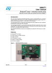
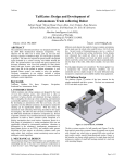
to a conclusion for our design, the Knight Industries Five Thousand (KIFT). KIFT is
pictured in Figure 1 below. In addition, KIFT is able to continually sample GPS
locations while executing an obstacle avoidance algorithm. KIFT is capable of
calculating a route to a specific latitude and longitude position using the onboard GPS
unit. KIFT is also able to seamlessly switch between manual mode (user mode) and
autonomous mode (pursuit mode) and is handled by the remote controlling application
created for controlling KIFT.
FIGURE 1: KIFT
KIFT‟s obstacle avoidance has been set for a precise measurement of 5 feet. When
KIFT senses an object, it implements the collision avoidance algorithms, allowing KIFT
to arrive at its destination safely. KIFT‟s drive train system is designed to be able to
have control over the microcontroller or user input with the remote control application.
The user can control KIFT from distances up to 100 meters due to KIFT‟s Class I
Bluetooth® architecture, which is enabled by a Bluetooth® module our MSI Wind
Netbook used for controlling of KIFT.
1
In Senior Design I, the problems of an unperfected autonomous vehicle were realized,
and meetings between the three group members shaped the process for a new design.
By the end of the first semester, KIFT‟s design was fully documented, and a plan of
action was established. In Senior Design II, after various designs and testing, KIFT‟s
main microcontroller is programmed to handle the GPS, Bluetooth® communication,
sonar sensors and drive train system. By the end of Senior Design II, KIFT‟s features
include:
Being driven using a MSI Wind Netbook (Laptop) with remote controlling
software or autonomously.
Continuously stream latitude and longitude coordinates from the GPS
Sampling of GPS waypoints are controlled by the remote control software.
Implement object avoidance measurements for protection during Pursuit Mode.
KIFT‟s circuitry is mainly comprised of a Bluetooth Class I module which interfaces
through UART directly with our microcontroller. The microcontroller has a direct input
from a GPS unit (also through UART), and receives a 32-bit NMEA coordinate stream
through digital inputs located on the microcontroller. This microcontroller also offers
enough I/Os to control the sensors and drive train system. There are two separate
power systems involved in KIFT, one used solely for the electronics onboard, and a
second which powers the drive train alone.
The project had a budget of $500, and was brought together by the three group
members. The largest contributor ultimately keeps KIFT, though the other two still
maintain patents of the design, and copyrights of the name. A list of the final budgeting
and materials, as well as materials acquisition, can be found in chapter eight of this
report. A list of suppliers with description can also be found at the end of chapter eight.
The report is divided into parts based on the flow of the design. First, we introduced the
task at hand.
In chapter two, initial technical content, we discuss the goals for
perfecting the design, as well as the milestones achieved in the two semester courses
of senior design. In chapter three, we research common methods being used for
controllers, wireless devices, power systems, mobility, and microcontrollers. In chapter
four, we narrow down our search and select components used in the production of
KIFT. Chapter five discusses the software integration of the selected devices, and
chapter six looks at the physical assembly of the parts. In chapter seven, we discuss
the testing process involved with KIFT, and explain our troubleshooting methods to
make KIFT work as designed. Chapter eight explains our budgeting process, as well as
how the parts were obtained. Chapter nine is the conclusion, and talks about the
different roles each team member took in the project, as well as our final thoughts on
the project. At the end of the report, we have our appendices and references, which
include permission emails, and component datasheets. You will also find a list of
figures included in the document, as well as the works cited sheet.
2
2.0
Initial Technical Content
2.1
Enhancing Existing Systems
Remotely Controlled vehicles have been extremely advantageous to our society over
the years. As technology evolves, the use for these RC vehicles also evolves. With
every step, we are greeted with the challenge of implementing these technological
advances. For our vehicle, we opted to upgrade the control system communication from
the traditional low frequency radio wave communication to one of the most widely
accepted forms of wireless communication today. We also opted to have KIFT be able
to drive itself without user input. KIFT is adaptable for many applications such as for
consumer electronics as an autonomous vacuum. In its simplest form, KIFT can be a
child‟s birthday present. In its more complex form, KIFT can be favorable to the defense
industry, which has a need for remotely controlled vehicles and unmanned vehicles.
We will mention DARPA later on in this paper, which specifically holds a challenge
every year for autonomous vehicles.
This chapter will comprehensively cover the steps taken by our team to perfect existing
systems with KIFT. In section 2.2, Project Goals, our team discusses the long-term
goals we intend to achieve with KIFT. These goals reflect the first thoughts our group
expressed with KIFT, even before the name of the project was chosen. Section 2.3,
project milestones, shows the steps taken each day of each month towards a fully
functional remote controlled vehicle. The KIFT project spans a total of 1 year over three
semesters, and every day is planned out ahead of time. We cover the reasoning behind
our time frames. Section 2.4, Evaluation Criteria, describes the different parts of the
project that had to be tested and evaluated. This includes, but is not limited to, testing,
documentation, reporting, and meetings.
2.2 Project Goals
The following items are goals accomplished with the fabrication of KIFT. The
challenging goals were achieved by KIFT and have been compiled into the following list:
Vehicle motion and speed control in which the vehicle can operate in drive mode
for at least 30 minutes, or pursuit mode for at least 5 minutes when the vehicle is
in operation.
The vehicle is controlled using our remote control software and with our MSI
Wind Netbook.
When the vehicle is in autonomous mode, it is capable of detecting an object in
its path within 5ft. of the vehicle. Implementation aversion tactics are not enabled
until a 2 foot distance is reached. Once the collision is avoided, KIFT will
continue on its designated path to its final destination.
3
In pursuit mode, KIFT is able to autonomously navigate to a user enabled GPS
waypoint. The onboard GPS system samples the vehicle position at every 4
seconds, and allows KIFT to continue its path to the destination point.
The power supply design for KIFT consists of primary and secondary power
sources. The primary power source will provide sufficient power to the vehicle
motor, gears control, and drive train system. The secondary power supply is
designed to power the other electronics on the vehicle such as our auxiliary PCB,
Bluetooth® module, GPS module, sonar sensors, microcontroller development
board, headlights, and light scanner. Having the two separate power supplies
allows KIFT to have a operation time of 30 minutes.
2.3
Project Milestones
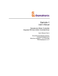
The group has developed a schedule of milestones for completing our initial design
documentation. Figure 2 below shows the development steps taken to produce our
initial design documentation paper. The development of our initial design documentation
paper was reflected by each group member‟s availability, as well as the general time
frames for researching parts.
As you can see in Figure 2 on the next page, our first day of the semester started on
January 10th. The actual project brainstorming didn‟t start until the 23 rd, and our initial
idea of KIFT was first documented on February 5th. The entire month of February, as
well as the first week in March comprises what you‟ll read below in Chapter 3:
Research. This ultimately was the foundation for our knowledge, and taught us most of
the technical jargon used in this presentation. From there, we continued to research
specific components capable of performing the tasks of the project. Once our team
decided 100% on the components needed for this project, we started to acquire them.
KIFT‟s controller was purchased off of eBay on March 24th, and arrived for us to test on
March 27th. Our team held off on purchasing other parts before the final Senior Design
documentation report was due, in case plans were changed at last minute. During April
22nd through 24th, 7-8 hour brainstorming sessions were conducted in the engineering
lab to finish up the critical portions of the paper. It was during these days that the
majority of our paper was completed.
4
FIGURE 2: SPRING SEMESTER MILESTONES
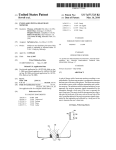
Figure 3 on the next page shows how our team actually planned to construct KIFT
during the summer semester. The blueprint for our vehicle is laid out in Chapters 5, 6,
and 7 of this Senior Design Documentation report. During the summer semester, we
focused on independently researching and working on KIFT, due to our availability to
meet as a group since each group member had summer internship commitments.
Artiom and Jason had some research findings for the various options available for our
Bluetooth® module. Koltan researched different options for our chassis also one that
has additional space for our electronics. Jason also researched different various options
for steering the vehicle such the possibility of using a digital compass. Artiom looked
into the programming needed for our microcontroller and GPS module.
5
FIGURE 3: SUMMER SEMESTER MILESTONES
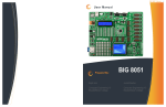
For the timeline for the Fall semester, we refer to Figure 4 on the next page. Jason and
Artiom continued microcontroller programming. Once the class has started back up, our
team met again with our advisor. The current design documentation at that time was reassessed with the advisor, and the plan of action was altered. We reassessed the
status of our project and made changes accordingly. Such changes included our vehicle
chassis, Bluetooth® module, and the microcontroller. A timeline of the progress of our
project is as follows:
•
September: Began PCB design. Acquired ALFATxp development board and
Evader chassis. Acquired and programmed GPS module.
•
Early October:
sonar sensors.
•
Late October: Acquired second Bluetooth module and attempted pairing with
SIXAXIS controller. Acquired Arduino Mega development board.
•
Early November: Produced initial object avoidance algorithm. Ordered custom
PCB.
•
Mid-November: Incorporated object avoidance algorithms with Pursuit Mode.
Installed components on MegaKIFT PCB. Decided to switch to laptop interface.
•
Late November: Acquired final circuit board and installed components.
testing
Acquired first Bluetooth module. Acquired and programmed
6
Final
FIGURE 4: FALL MILESTONES CHART
2.4
Evaluation Criteria
Each phase in the design and testing of the prototype will be documented immediately
for future reference. The documentation will provide a clear understanding of how our
prototype is designed to operate.
Technology selection: After researching available options for the component
design of the project, the technology necessary for our prototype is selected and
compared against other components. Subsequently, hardware acquisition
begins as well.
Prototype design: have a design with specific and practical functions for the
product. Also, KIFT design stems from the capabilities and features of the
various selected parts and how they can contribute to the overall success of KIFT
goals.
7
Prototype implementation: building and putting together the different part of the
product. The implementation of KIFT is extremely important in an precise manner
it allow for KIFT to operate efficiently and meet the projected objectives.
Prototype testing: Integrated testing will be used, each component will be
tested separately before the complete device is assembled and tested.
Prototype documentation: Product interfaces such as a user manual and
maintenance procedure, test procedure will be documented.
Project reporting: This Senior Design project will be completed in two
semesters. During the first semester, the following reports and deliverables shall
be submitted:
1. Weekly e-mail updates
2. Weekly update of documentation paper
3. Status report of technology acquisition
Research: When selecting the technologies for this device, extensive research and
discussion among team members and with faculty advisors was completed. All
methods were researched completely, and the cheapest, most accepted form of any
technology was ultimately chosen for KIFT.
8
Chapter 3: Research
3.1
Introduction
Now that we‟ve constructed a basic plan of action for our project, it‟s time to research
the technologies associated with it. We‟ve decided to build a remotely controlled car
called KIFT. KIFT‟s main purpose is to drive autonomously to waypoints programmed
by a GPS and stored in memory. KIFT operates autonomously and is equipped with
sonar sensors for object detection and avoidance.
This chapter starts out with section 3.2, which covers existing autonomous vehicles.
Before a system can be perfected, one must first understand how the initial system
works. This section will take a look inside KIFT‟s predecessor, K.I.T.T., as well as the
Mars Rover Lander, and the DARPA Urban Challenge vehicle. We will then move on to
section 3.3, control methods, to discuss different options for controlling KIFT. There are
many different ways a robotic car can be controlled, and while KIFT comes standard
with an autonomous mode, it must still be controlled in order to find the GPS waypoints
it‟s meant to drive to. Section 3.4 deals with the power supply of KIFT, and discusses
the means to power such a vehicle. Batteries are a must in this instance, but which
type? Which voltage? What current? These are all valid questions to be addressed.
Section 3.5 discusses voltage regulators, and is essentially a branch of section 3.4.
Once a battery type has been selected in section 3.4, we must make absolutely sure it
will not fry the components. Further, we must design a regulatory system such that
KIFT‟s electronics will not suffer any consequences, provided the control system
receives any “hiccups.” Section 3.6 gives us an introduction to microcontrollers, as well
as their use for our project. Most of the integral parts of KIFT cannot function as standalone parts. They must have a central “brain” to convey which data must be
manipulated, and what can be thrown out. The microcontroller becomes one of the
most important components in the design of a robotic device, and ultimately becomes
the most time-consuming later on in the prototyping chapter. Moving on to section 3.7,
we reach a system quite difficult to straighten out if not set up properly, wireless signals.
When we refer to wireless signals, we refer both to radio frequency (RF), as well as the
GPS system itself. Subsections 3.7.2.1 and 3.7.2.2 deal with the NMEA and SiRF data
streams, which are implemented into microcontroller design later in the paper. Section
3.8 deals with mobility, and is an integral part of our system since we want KIFT to be
able to move. One of the most common robotic mobility methods, the H-Bridge, is
observed in subsection 3.8.1 of this section. Finally, we take a look at object avoidance
and its role in the safety of KIFT through its “Pursuit” mode.
9
3.2
Autonomous Vehicles
As mentioned earlier in the Introduction, we must first take a look at previous
autonomous vehicles before our team can perfect them. The basis of KIFT‟s design is
on the Knight Industries Two Thousand, or K.I.T.T. for short. K.I.T.T. was a lab-built
supercar developed by Knight Industries in 1982. Built on the shell of a 1982 Pontiac
Firebird Trans Am, K.I.T.T. was able to accelerate from 0-60 in 0.2 seconds (with turbo
boosters enabled) and the top speed of K.I.T.T. doesn‟t seem to be documented. The
market price for K.I.T.T. was estimated at $11,400,000, and its body was built of a
classified material that was virtually indestructible. The vehicle contained rudimentary
functions such as a flame thrower, rocket boosters, a smokescreen, and oil jets, as well
as a few necessities, such as turbo boost, pursuit mode, and auto cruise with collision
avoidance [17]. While KIFT doesn‟t have the room to implement such things as a
smokescreen and oil jets, it must have auto cruise and pursuit mode.
One of the most widely known remote control vehicles, the Mars Rover, was invented
by the National Aeronautics and Space Administration (NASA). NASA uses the Mars
Rover to explore Mars‟ surfaces, as well as soil content, in the hopes of discovering
ways to support human life. While the Mars Rover has many technological advances,
such as having a camera onboard and a remote shut off, one of the features that stands
out the most is the ability to communicate from Mars back to Earth - a distance of
approximately 36 million miles. While KIFT may not be able to communicate 36 million
miles, it will be able to flawlessly transmit data over a distance of ~100 feet.
The Defense Advanced Research Projects Agency (DARPA), hosts the Grand
Challenge every year. DARPA is the main research organization for the Department of
Defense, and looks to perfect autonomous vehicles every year. Each year, different
teams around the world turn full-size vehicles into autonomous vehicles. In May 2006,
the Grand Challenge became the Urban Challenge, having teams attempt to
successfully navigate courses in a tight, urban environment, as shown in Figure 5
below. Like the DARPA Grand Challenge, KIFT can revolutionize modern warfare by
tracking GPS paths and possibly implement decision-making in future models. If future
war zones could be full of KIFT models rather than soldiers, it would save hundreds of
thousands of lives [24].
FIGURE 5: DARPA URBAN CHALLENGE MIT VEHICLE
Image re-printed with permission from DARPA
10
3.3
Control Methods
The control method of KIFT is essential to the overall success of KIFT‟s design. There
are various control methods that can be used to remotely control KIFT - for instance, the
conventional radio frequency remote controller, a cellular phone, laptop computer, or a
Bluetooth controller such as Sony® PlayStation®3 SIXAXIS™ Controller. These
controllers have individual advantages and capabilities. With that being said, one of the
main objectives of KIFT is to modernize the traditional control method of RC vehicles by
incorporating Bluetooth as a means of communication. At the same time, we want to
have a controller that is power efficient, more mobile and cost effect than its
competitors.
3.3.1 Remote Controller
The remote controller for the vehicle serves as the main control unit to dictate the
direction the vehicle will move. The remote controller is also capable of controlling the
speed of the vehicle. The common choice for a wireless controller for a remote
controlled vehicle is one that operates by radio frequency. The simple description of
how a radio frequency controller operates is that the controller sends out a signal and
the receiver on the vehicle establishes a communication network from inputs (joysticks
and throttle control) and outputs (movement of the vehicle). Therefore, the purpose of
the radio-frequency controller is to eliminate the hassle of having a lot of wires in order
to control the vehicle and increase the mobility. There are other forms of remote
controls that use radio frequency such as cell phones or laptop computers.
3.3.2 Sony PlayStation®3 SIXAXIS™ Controller
Introduction
The foundation for the video gaming industry is to make games as realistic as possible.
They do this by continuously striving to incorporate every detail of reality into their form
of a virtual reality. This virtual reality is what causes the gaming experience to be so
thrilling for the consumers. The games of today are so far advanced that on some
occasions it is difficult to differentiate between virtual reality and reality itself. As the
video gaming industry is reaching a plateau for its graphical standard, in being able to
simulate our reality with every attention of detail in establish the worlds or the
environment that these games are set in. The industry is forced to move to another
aspect of the gaming experience to keep the interest of their consumers. The industry‟s
trend is having the controller pad with a motion sensitivity system, where along with
buttons on the controller pad, and analog joysticks, the motion of the controller pad acts
a directional input control. Therefore, to stay on the competitive edge in the video game
industry, Sony has opted to incorporate with the Playstation®3 controller SIXAXIS™
motion sensitivity technology.
11
Design Features
The design of the Playstation®3 SIXAXIS™ controller is a significant upgrade from its
predecessor of the Playstation®2 DualShock Controller. At a glance, the visual
difference between the two controllers is that the Playstation®3 SIXAXIS™ Controller is
wireless as opposed to the Playstation®2 Controller, which is a wired controller. The
Sony PlayStation®3 SIXAXIS™ controller connects wirelessly to the Playstation®3
console via Bluetooth connectivity from the controller to the Playstation®3 Console.
Another new design feature of the Sony PlayStation® SIXAXIS™ controller, is its
internal rechargeable battery that is capable of being charged by connecting the
controller to the Playstation®3 console via a USB syncing cable which will give the
controller a battery life for 30 hours.
Another feature to the Sony PlayStation®3 SIXAXIS™ controller is similar to Sony‟s
counterpart, the Microsoft XBOX 360 controller with the Home button- a button in the
middle of the controller used for powering the controller as well as turning on the
console. Another improved feature is the joysticks have more precise control and a
wider range of motion. This is achieved by increasing the titling angle of the joysticks
and makes them more sensitive to change in motion [7].
SIXAXIS™ Technology
The pivotal design feature is the SIXAXIS™ motion sensor technology and in turn
enhances the gaming experience with the analog control directional input. As the name
suggests, the Playstation® 3 SIXAXIS™ Controller senses motion in six directions: up,
down, left, right, forward, and backward. The SIXAXIS™ Technology has the ability to
senses both rotational and translational movement along all three dimensional axes,
providing 6 degrees of freedom. The six degrees of freedom refers to the motion of
rigid bodies in 3-dimensional space and movement along the three axes act
independently of each other as shown in Figure 6 below [7].
The incorporation of the SIXAXIS™ technology improves game play with freedom of
movement and allows the gamer to become more involved with the gaming experience
and helps with creating that belief of reality. The immense innovation of the
Playstation®3 controller is that SIXAXIS™ motion sensing technology is achieved from
the built-in hardware of the controller and also the Bluetooth® connectivity with the
console. The Nintendo Wii remote requires an infrared receiver attached to the console
to capture movements. The new design features and SIXAXIS™ Technology of the
Sony PlayStation® SIXAXIS™ controller is an attractive and excellent match for our
vehicle, KIFT.
12
FIGURE 6: SIX DEGREES OF FREEDOM
Image re-printed with permission from Newport Corporation
3.3.3 MSI Wind Netbook
Another option for controlling KIFT is the MSI Wind Netbook, since using a laptop gives
us many options for the communication network between the laptop and the vehicle.
The computer would run our software controlling the vehicle and enable the directional
keys on the computer to be reflected with the movement of KIFT. Also, by using the
computer as our controlling device we‟re able to have visual feedback to the user to see
their inputs and the display of the vehicle movement.
3.4
Power Supply
For our vehicle, KIFT to reach its full potential, it‟s imperative that KIFT have an
adequate and reliable power supply, and that each component on the vehicle will
receive the required voltage for operation. When powering KIFT, we have implemented
two power sources: a primary source exclusively for supplying power to the motor, and
a secondary source for the additional electronics. However, before any designs of a
secondary power supply begin, it is necessary to find out voltage ranges and
operational voltages for each electrical component that needs to be powered. The
component‟s voltage information can be found in the Figure 7 below:
13
FIGURE 7: COMPONENTS VOLTAGE REQUIREMENTS
The power supply for KIFT must be capable of providing power to all the electrical
components to ensure that KIFT will be fully operational. The power distribution system
for KIFT shall consist of the direct current (DC) motor, H-bridge, GPS module, Bluetooth
communication module, sonar sensor (for object detection), and the microcontroller.
More importantly, we must have a power supply design solution that is capable of
providing the required voltage to the various components for at least 30 minutes for
vehicle operation. Our power supply design operates efficiently regardless of
environmental elements, whether during operation on an enclosed course or outdoor
course. Based on our research results we have a few available options for battery
types for our power supply design. The battery options for the power supply design
differ from one another in cost, type, and charging capacity. The power supply battery
options are between alkaline, nickel-cadmium, and nickel-metal hydride.
3.4.1 Alkaline Battery
The ideal battery for our power supply design would be an alkaline battery because they
are widely accessible and can be easily connected in series to increase the voltage
output level. Also, depending on the alkaline battery size determines the amount of
discharge current from the battery. For instance, the bigger size of alkaline batteries
such as D cell or C cell batteries have applications for flashlights and radios as opposed
to the smaller sizes of AA or AAA alkaline batteries are use for MP3 players and other
smaller consumer electronics. Granted, alkaline batteries have a lot of advantages such
as being inexpensive, readily available, and the ability to take standard 1.5 V alkaline
and be able to increase the voltage output by combining several 1.5V alkaline batteries
in series to achieve the increase in voltage output. However, a major disadvantage of
alkaline batteries is their ability of being able to re-charge; and if so how much voltage is
charged back to the battery. Another negative about rechargeable alkaline batteries is
that they do not retain their charge capacity after being recharged as long as
manufactures specified and also to re-charge the alkaline batteries, they are only
capable with their manufactured specific charger [18].
14
3.4.2 Nickel-Cadmium Battery
Another battery type that is typically used in consumer electronics is the nickel cadmium
(Ni-Cd) battery. This battery can be beneficially used for the power supply design of
KIFT. The Nickel cadmium (Ni-Cd) battery is comparable to the alkaline battery given
that they have similarities in voltages, consequently the nickel cadmium (Ni-Cd) battery
has 1.2 V and alkaline has 1.5 V.
The nickel cadmium (Ni-Cd) battery also outperforms the alkaline battery because of its
low internal resistance, which causes the nickel-cadmium battery to have a large
amount of discharge current to the power supply of KIFT. It will allow every component
to receive its required voltage in a timely fashion. The Nickel cadmium (Ni-Cd) batteries
ability to provide large amounts of current is why it will be an optimal choice to be use in
the robotics industry. Although the nickel cadmium (Ni-Cd) battery positives tend to
outweighs its negative, however the one major negative factor of have nickel cadmium
(Ni-Cd) battery is the “memory effect.” The “memory effect” occurs in nickel cadmium
(Ni-Cd) rechargeable batteries and causes them to hold less charge. In the process of
charging, the power source was abruptly disconnected, which causes the nickel
cadmium (Ni-Cd) battery to remember it‟s last less charge state, and the nickel
cadmium (Ni-Cd) battery batteries gradually lose their maximum energy capacity if they
are repeatedly recharged after being only partially discharged [18].
3.4.3 Nickel Metal-Hydride Battery
The Nickel Metal-Hydride (Ni-mH) Battery is very similar in chemical makeup to the
nickel cadmium (Ni-Cd) battery in respects that it has a similar voltage of 1.2 Volts and
has low internal resistance and will result in have larger discharging currents. Some
disadvantages associated with the use of Nickel Metal-Hydride batteries is the cost and
shelf life. Nickel metal-hydride (Ni-mH) batteries tend to be priced slightly higher than
the nickel-cadmium (Ni-Cd) battery and the shelf life of a nickel-metal hydride battery.
Nickel Metal-Hydride (Ni-mH) batteries will lose approximately thirty percent of their
charge each month even without use [18].
3.5
Voltage Regulator
The power supply design for KIFT must be capable of supplying voltage to the motor of
5 Volts and also maintain the voltage levels for the other vehicle components. This can
be achieved by implementing a voltage regulator to the power distribution system of the
vehicle. A voltage regulator circuit is designed to output a constant voltage that‟s not
the same as the input voltage similar to a transformer in a utility power distribution
system. The transformer enables two different elements to receive the required voltage
without varying the input voltage (power source). Ideally with regard to power supply
design, input voltage directly from a power source will connect voltage the regulator
circuit and the constant output voltage will maintain the operational voltage level of 5V
to the vehicle electrical components. The voltage regulator circuit can be incorporated
15
by a simple series regulator circuit, which consists of a transistor, a zener diode and a
couple of resistors as in Figure 8 below.
FIGURE 8: SIMPLE SERIES REGULATOR CIRCUIT
Another possible option of a voltage regulator would be a linear regulator, it‟s similar in
nature to the simple series regulator, but the linear regulator usually is available as an
integrated circuit. The linear regulator integrated circuit is available in fixed or variable
output voltages. There are many different varieties of voltage regulators available, after
researching we have selected two voltage regulators, the LM7805 and the LM723 as
possible options for the KIFT. These two integrated circuits were chosen based on
regulated output voltage, as well as their availability, costs, and features. In our final
design, the proper voltage regulator is implemented in the microcontroller, throwing
away the need to install and use our own voltage regulator circuit.
3.6
Microcontroller
Whenever there are several components that must be controlled in a non-sequential
manner it is always helpful to rely on a microcontroller. Microcontrollers have similar
functions as processors in a computer. If coded correctly, a microcontroller can
substantially reduce the number of analog connections in a circuit. Other options of
digitally controlling a circuit include programmable gate arrays (PGA‟s) or
programmable logic controllers (PLC‟s). All of these methods would solve the problem
of controlling a remote controlled car through Bluetooth while implementing GPS. The
problem comes in on the performance aspect of the PLCs and PGAs. Using those to
control a remote controlled car is like trying to kill a fly with a bazooka. It is most
definitely overkill.
16
Because KIFT had several features that involved digital transmission and reception of
data, the use of a microcontroller was unavoidable. The problem then was to decide on
which microcontroller to use. There were several factors which needed to be
considered. The first and foremost thing that needed to be considered was the number
of available pinouts which would be necessary to fully operate all parts of the vehicle. In
addition to having sufficient ports, the microcontroller that will be placed in KIFT must
have the ability to process GPS and store the NMEA stream for later retrieval. As we
found out, there are several formats in which the GPS chip can output the coordinates
based on the standard NMEA stream called every n seconds. The type of output that
we will be working with is RMC.
3.7
Wireless Signals
Our vehicle requires a controlling mechanism, as well as GPS coordinates to function.
While it goes without saying that a GPS for a moving vehicle obtains coordinates
wirelessly, control methods are not exactly the same. Some electronic cars are not
controlled remotely, but with a wired controller instead. In this section, we will be
examining the possibilities of wireless control methods, as well as the need for a
wireless GPS module in our system.
There are many different wireless signals that are used as control methods. Most of
these are Radio Frequency (RF), but the differences lie in the bands they operate in.
We plan on using a wireless signal as a control method for our vehicle, but which signal
type should we use? The options we consider include WiFi (wireless internet), IrDA
(Infrared), cellular phones, Bluetooth, and other altered versions of these. Each of
these control methods have their respective uses, but we want a controller that gives us
the freedom of customization for our system. In the sections below, we examine the
positive and negative aspects of each RF control system, as well as GPS stream data.
3.7.1 Controlling Through Radio Frequency (RF)
Let‟s first have a look at WiFi signals for control methods. WiFi requires placing an
access point on the vehicle itself, and involves decryption methods to retrieve data from
the signal itself. The other downside of WiFi is the need of a computer to control the
car. We‟d rather not lug a laptop around everywhere we go, and it‟s rather hard to
control a vehicle properly using keys rather than joysticks, so we throw WiFi out the
window right away.
Infrared (IrDA) replaced cabled communication, and essentially required two devices to
be aimed directly at each other within a 1 meter distance. This method was flawed in
that it could not penetrate solid walls, but there were definitely some advantages.
Infrared is still the primary technology used in television remote controls, mainly
because infrared only pairs two devices. In a room full of televisions, a single infrared
remote (should) only power on and control one television. The use of two-device
pairing also prevents interference, since the television (or other infrared controlled
device) isn‟t monitoring other frequencies. Unfortunately, this two-device constriction
prevents a person from using a single device to control multiple receivers [1].
17
Cellular phones can be used to control vehicles too. Many people have used devices
such as the Apple iPhone to control their vehicles. While this offers a lighter alternative
to a computer, the capabilities are somewhat slim, and it‟s not as widely accepted for a
control method. It does, however, allow the user to control the vehicle from almost any
distance away. This is attributed to the fact that it uses the cell phones service provider
to provide commands. The vehicle decodes the key tones and translates them to
commands for a microcontroller [15]. In addition to not having a spare phone to donate,
we wanted more flexibility for inputs.
3.7.1.1 Bluetooth®
We now come to the wireless technology of our choice. Bluetooth® communication is
one of the cheapest and widely used wireless communication methods, and has
numerous advantages over other radio signals. Not only does it focus on low power
consumption, but Bluetooth® can be a more reliable means of wireless communication
by establishing a connection (or pairing with a device) which leads to interference-free
communication. Bluetooth® communication can also increase the range for controlling
the vehicle.
There are three classes of Bluetooth®: Class 1, Class 2, and Class 3. Of these three,
Class 3 uses the lowest power (1mW) and has the shortest range (~1 meter). Class 2
immediately follows with its 2.5mW power requirement, and a range of ~10 meters. The
most powerful of the three then becomes Class 1, which operates a distance of ~100
meters with a power consumption of 100mW [1]. Since we need a range larger than 1
meter for our project, Class 3 is immediately dismissed. A range of 100 meters for a
Bluetooth® Class 1 module is ideal for KIFT‟s communication system. Therefore, we
narrowed search to just a Bluetooth Class 1 compatible transmitter and receiver.
Bluetooth® uses low-power radio waves at a frequency of 2.400-2.4835 GHz in the
Industrial Scientific Medical (ISM) band. This is located above television frequencies
(~1 GHz) and below Satellites (~10 GHz). At the center of this spectrum are RF
channels 0-78, as shown in Figure 9 below. The first 2 MHz of the spectrum, as well as
the last 3.5 MHz of the spectrum are used as “Guard Bands” to comply with “out-ofband regulations in each country” [1]. The ability to pair different devices within the
same spectrum allows for a broader spectrum of use.
FIGURE 9: BLUETOOTH® SPECTRUM
Bluetooth® 1.0 and 1.0B were the first versions to be introduced, and had many
connection problems. Bluetooth® 1.1 was introduced shortly after, and corrected many
18
of the connection problems that 1.0B faced. Bluetooth® finally became mainstream
with the release of Bluetooth® 1.2. Faster connection and discovery were made
possible, and the quality of the signal was massively improved. Speeds of 1 Mbit/s
were achieved, and Bluetooth® headsets became common for in-car communication. In
2004, Bluetooth® 2.0 was released with the introduction of Enhanced Data Rate (EDR).
This increased the average speeds from 1 Mbit/s up to 3 Mbit/s, and also provided for a
reduced duty cycle, delivering lower power consumption [1]. Thus, our Bluetooth Class
1 module should be at least Bluetooth® 1.2 compliant or higher.
3.7.2 Determining Position
In order for KIFT to implement the GPS navigated autonomous mode, a sort of tracking
device was needed. The general method for pinpointing an object in space one needs
to use other objects as reference. This process is referred to as triangulation. In
triangulation at least 3 objects are used in order to pinpoint the location of the object in
question. There are several technologies available on the market today that use
triangulation. Some of these technologies include: GPS, Cellular, and a series of
custom built and seldom deployed RF networks.
3.7.2.1 WiFi and RF Position
Other methods can be used to get the position of the object. So long as there are at
least 3 points of reference even a simple local RF network can be used. Methods such
as local Wi-Fi can be used in cases where there are multiple hot spots in a particular
area and a user has access to at least 3 hot spots. Such networks have an
implementation on sites such as a college campus where there is enough access points
in order to triangulate a position of a person.
3.7.2.2 GPS Position
Global Positioning System (GPS) or Global Navigation Satellite System (GNSS) uses a
series of satellites in order to pinpoint an abject on Earth. The user must be in constant
contact with at least 4 out of the 24 satellites in orbit in order to calculate the correct
location [12]. The GPS satellites broadcast their location as well as a list of the
approximate locations of all the other satellites in a series of sequential CDMA
messages. CDMA or Code Division Multiple Access implements partitioning of the band
on a code level. This means that all satellites can use the same band to broadcast their
code. The GPS receiver is tuned to the GPS L1 band at 1575.42 GHz gets to get the
message. Once the message is received, the unit extracts the location information as
well as the time information from and compares that information to the information
obtained from the other satellites. Based on the timings it determines its position with
reference to the other satellites [ 11].
19
While cellular and RF triangulation provide positions that are slightly more exact than
that of the GPS, the cost of implementing these techniques is also high. Additionally,
these systems have a very limited range. The GPS technology available today is will
allow us to implement a relatively inexpensive solution for our project. This led us to
decide to continue with the GPS research. The next step towards having a working
module on our project was determining which particular chipset and module we needed.
For that it was necessarily to find out the advantages and the drawbacks of each
chipset and how it fit into the general problems of the GPS system.
There are one or two problems that may be causes for concern. The first problem
comes from the distances between the receiver and the satellites, as shown in Figure
11 below. All orbital satellites are equipped with sophisticated cesium and /or rubidium
clocks (atomic clocks). In order for the receiver to be as precise as the satellites, it will
have to also be equipped with such a device. Due to cost constraints, it is completely
unpractical for each GPS receiver to be equipped with an atomic clock. Therefore, a
fourth satellite is used in conjunction with the other 3 in order to correct the error in the
receiver's clock. Once the 3 positions are approximately known, the only missing
variable is (t). The equations are then solved with a single unknown and the receiver's
reference clock is corrected to match the satellite time [11].
FIGURE 10: TRIANGULATION ERROR
(Image re-printed with permission from Robert H. Biggadike under GNU Free Document License)
The importance of time cannot be overlooked. Since the GPS receiver establishes its
position based on the time it takes a signal to travel from the satellite to the receiver, a
millisecond (.001s) can result in a 3 m deviation because of the large speed of light
constant. Hence, the fourth dimension, t, established the precision of the GPS receiver.
After taking a closer look at what the signal is composed of, we can see that instead of
one signal, there are multiple signals intended for different types of users. All satellites
broadcast two different frequencies labeled L1 and L2. L1 is the more widely used one
of the two and is intended for general civilian use. The frequency for L1 is 1.57542 GHz.
Satellites implement a Code Division Multiple Access (CDMA) system which allows
every satellite to use the same band [11][10].
20
3.7.2.3 Cellular Position
The cellular triangulation, also known as cellular geo-location technology, relies on the
local towers, a series of hotspots, and to triangulate its position and is generally used
by 911 in case of emergencies in order to pinpoint the location of the mobile device from
which the call came from. In any area a cell phone will be connected to at least 1
broadcasting tower at a time. From there it determines its approximate position which is
then correlated with the GPS coordinates [22].
3.8
Mobility
The cornerstone objective of KIFT is for the vehicle to actually have movement remotely
controlled through Bluetooth communication. More importantly, the challenge is how to
control the movement of the vehicle in the most cost efficient manner. The plausible
options include having a sophisticated drive train system of autonomous vehicles as
seen at multi-million dollar theme parks such as Disney or Universal, or spending a few
dollars on an H-bridge.
Another method for controlling the mobility of KIFT is using caterpillar tread. Caterpillar
treads are moved by a toothed drive wheel, driven by the motor and engaged with holes
in the track links or with pegs on them to drive the track. The drive wheel is typically
mounted well above the contact area on the ground, allowing it to be fixed in position.
Placing a suspension on the driving wheel is possible, but is mechanically more
complicated. A non-powered wheel is placed at the opposite end of the track, primarily
to angle the front of the track to allow it to climb over obstacles, and also to tension the
track properly loose track could be easily thrown off the wheels. The caterpillar tread is
a mobility method that incorporates the rotation of the wheels with the rotation of the
motor directly. However we can take the more conventional route of using the H-Bridge
that is commonly used in the robotics community for the controllability of their robots,
but in this instance our vehicle. However we can take the more conventional route of
using the H-Bridge that is commonly used in the robotics community for the
controllability of their robots, but in this instance our vehicle.
3.8.1 H-Bridge
First, the DC motor operates when in the presence of a direct current being supplied by
power source, which the positive terminal of the power source connects to the positive
terminal of the motor and the same connection technique for the negative terminal. With
this configuration the motor will spin in a positive “forward” direction (clockwise) and by
simply changing the polarity will cause the motor to spin in a negative “reverse” direction
(counter clockwise). To continuously control the changing of polarity of the power
source to determine the direction of the motor can be accomplished by using an Hbridge. The H-Bridge circuit is a commonly used for controlling the current through a
DC motor. The name of the H-Bridge comes from the shape of the actual circuit. A
visual representation of the H-bridge circuit is found in Figure 12 below.
21
FIGURE 11: A SIMPLE H-BRIDGE CIRCUIT
(Image re-printed with the permission of Botskool)
The simple design of an H-Bridge has 4 switches in total, were 2 switches are
connected to the motor power supply positive terminal (High Side Left/High Side Right)
and 2 switches are connected to the motor power supply negative terminal (Low Side
Left/Low Side Right). As well as, there will be 2 switches connected to the motor
positive terminal (High side Left/ Low Side Left) and 2 switches will be connected to the
motor negative terminal (High Side Right/ Low Side Right). As shown in Figure 13
below the S1 & S4 are closed (enabled) to allow the flow of the current the motor and
cause it to rotation in a “positive” forward direction (clockwise).
FIGURE 12: H-BRIDGE MOTOR IN FORWARD DIRECTION
(Image re-printed with the permission of Botskool)
To logically determine the direction the motor will spin a simple 4 bit truth table can be
constructed. The truth table in Figure 13 below shows logically which switches need to
be closed, so that the current from the power supply will a complete path to travel and in
return cause the motor to spin [8].
22
::
FIGURE 13: TRUTH TABLE OF DC MOTOR DIRECTION DETERMINED BY H-BRIDGE
H-Bridges are commonly use in the Robotics community. The types of circuits also are
available in various types such as with relays, discrete components, and integrated
circuits. Figure 14 below is an example of an H-Bridge using relays.
FIGURE 14: H-BRIDGE CIRCUIT
(Image re-printed with permission from Power-IO)
The H-bridge circuit is very beneficial in electronically controlling the motor direction for
KIFT. The microcontroller we‟ve selected for our project has an H-bridge built into it, so
we have no need for designing our own circuit.
3.9
Object Avoidance
KIFT will have the feature of going into Pursuit Mode after selecting the vehicle mode of
operation on the remote control software. In Pursuit Mode, it is essential to avoid object
collision while in route. To prevent this, we implement object avoidance through
sensors. This keeps the vehicle from damaging itself while replaying the GPS
coordinates for its path. For object detection and avoidance to be achieved, we will
need to implement some type of sensor which will report the distance of an object from
KIFT. The most common types of sensors are motion, color, thermal, sonar, light,
touch, and sound, to name a few. We obviously don‟t want a motion sensor since our
vehicle will be constantly moving. Color is out of the question, because we want KIFT
23
to avoid all objects, not just objects of a certain color. Thermal isn‟t a big deal either,
since we want KIFT to avoid objects of any temperature. Sonar would work, since it
doesn‟t rely on speed, color, heat, or any other generic measures. Light doesn‟t matter,
since we don‟t want to run into objects in the dark. Touch would work, but it would be a
little too late since we don‟t want KIFT to actually interact with something. Finally,
sound doesn‟t matter since our objects will not necessarily be making noises. Through
this research, we come to the conclusion that we need sonar sensors for KIFT.
Sound navigation and ranging (sonar), was originally used underwater for submarine
vessel detection, but is now used for any type of object detection through sound. A
sonar sensor emits a “sonar pulse” at a specific transmission frequency. This pulse
makes contact with an object and the pulse is reflected back towards the sensor as
shown in Figure 15 below. Once the pulse is intercepted back into the sensor, the
distance is calculated using the speed of sound combined with the time interval
between pulse and interception. Using an average air temperature as 75 degrees
Fahrenheit, we obtain that our sound through air constant is ~1135.079 feet/second [2],
the calculation is performed as an example below:
X seconds * Y feet/second = Z feet
So, 4.405 milliseconds * 1135.079 ft/s = 5 feet
FIGURE 15: SONAR ECHOING
Because of the precision involved with these sonar sensors, we want a sensor that will
detect an object up to 10 feet away. This gives KIFT enough time to implement
avoidance algorithms, no matter what speed it‟s traveling. We will also be needing
sensors for each corner of the vehicle, so the sensors should be inexpensive. Thus, we
are looking for light, inexpensive sonar sensors that have a range of 10ft minimum.
24
Chapter 4: Component Selection
4.1
Introduction
The following section includes the various technology and parts we have decided to use
in constructing our vehicle, KIFT. With each selection of technology it will include the
advantages and disadvantages of possible option for each technology section. Also,
with the selected device will include reasoning to why we feel the various parts will help
KIFT achieve its projected goals.
4.2
Researching the Knight Industries Two Thousand
The Knight Industries Two Thousand (K.I.T.T.) is the vehicle that was use in the 1980s
hit television series Knight Rider. At the time of K.I.T.T.‟s release, it was a futuristic
vehicle that had features that were unimaginable at the time. K.I.T.T.‟s features included
a voice synthesizer, computer artificial intelligence, turbo boost, super pursuit mode,
telephone communication link, and surveillance mode. K.I.T.T. also had the capability of
being autonomous as well. Also, some of these features that seemed unimaginable
back in the 1980s are now available in vehicles of today. However, the reason we chose
to use a scaled down version of KITT for our vehicle chassis is because the features of
this fictitious vehicle are similar to our design features for our vehicle. A particular
feature is the super pursuit mode, where K.I.T.T.‟s computer artificial intelligence would
program itself with a destination GPS coordinate and cause K.I.T.T. to autonomously
be in route to destination at top speeds. This super pursuit mode is similar to pursuit
mode for KIFT, where when KIFT is put into pursuit mode the vehicle is able to navigate
autonomously by way of input GPS coordinates that were saved from the vehicle motion
in drive mode. Because of these similarities in features between K.I.T.T. and our vehicle
this is why we selected a replica of KITT. The selection of K.I.T.T. as our vehicle
chassis will also allow us to incorporate a theme with our senior design project [17].
We initially decided to modify the K.I.T.T. car from Hitari shown in Figure 17 on the next
page. This remote controlled car was chosen for its size, and its likeness of KIFT. The
Hitari K.I.T.T. is a 1:15 scale replica of the original K.I.T.T., and measures 337mm (~13
inches) in length. The replica also weighs 0.5kg (~1.1lbs), so it will move fairly fast
because of its weight.
25
FIGURE 16: HITARI K.I.T.T.
(Image re-printed with permission from Hitari)
The K.I.T.T. model operates from 1x 9V and 4x AA batteries. However, the power
supply design for KIFT consists of a primary source and a secondary source. The
primary source would contain a battery pack of 4x alkaline C-Cell batteries and would
be responsible for the vehicle motor operation. The secondary source would consist of a
9V nickel metal hydride (Ni-mH) rechargeable battery and would be responsible for
powering the other electronics of the vehicle such as the Bluetooth module,
microcontroller, GPS module, and the sensors.
4.2.1 Modifying the Hitari K.I.T.T.
The Hitari K.I.T.T. car is not usable straight out of the box. There isn‟t much room
inside, so we‟d need to modify the internals. The underside of the Hitari K.I.T.T. model
can be seen in Figure 17 below. You can see the battery pack in the bottom right
corner of the image below. These 4x AA batteries work alongside a 9V battery to run
the car. We would need to leave the 4x AA battery compartment intact, since they
power K.I.T.T.‟s scanner, head-lights, tail-lights, and noises.
FIGURE 17: UNDERSIDE OF HITARI K.I.T.T.
26
We can also see the two switches on the underside. These are directly connected to
the 4x AA and 9V battery on K.I.T.T. The switch that controls the 4x AA batteries would
have to be left alone, since we won‟t need lights and sounds while testing KIFT. The
second switch, which controls the power of the 9V battery, would be spliced along with
our 4x alkaline C-Cell batteries. In the absolute center of Figure 17 above, we can see
three holes for screw access. Once the screws are removed, the top of K.I.T.T. lifts off
as seen in Figure 18 below. We can see the scanner mounted just under the “hood” of
K.I.T.T. This scanner is taped in place, and can be removed easily. We can also see
the blue and black leads that run back to the tail-lights. These need to be kept for
reverse functions. The main motherboard is located in the center of K.I.T.T., and would
be replaced with the microcontroller later on. There is space behind (towards the rear)
this board where the Bluetooth module could be mounted.
FIGURE 18: INSIDE OF HITARI K.I.T.T.
Moving back to the scanner on K.I.T.T. (as shown in Figure 19 below), we see that it
consists of five red LEDs mounted on a small PCB. This PCB can be removed easily
with two screws. There is a clear piece of Plexiglas which allows the viewer to see the
scanner on the front. The Plexiglas is fogged, giving a fade effect to the LEDs when
they scan. The “head-lights” are also located on the far right and left of this board. We
can remove these parts and modify them so that we do not perform copyright
infringement on K.I.T.T.‟s scanner by calling the car KIFT. These would be switched out
with bright blue high rated LEDs, since KIFT uses a blue scanner. Now that the screws
have been removed, we get a good clear look at the LED board on the front.
27
FIGURE 19: MOUNTED SCANNER ON K.I.T.T.
Thus, we intended to remove some excess plastic from the interior of the Hitari K.I.T.T.,
giving us more room for our Bluetooth development board, as well as our
microcontroller development board. We also intended to change the scanner lights out
to reduce the chance of copyright infringement. Due to the intense modification needed
to make this car our chassis for KIFT, we opted to get a larger more robust vehicle
chassis.
4.3 Evader 1:10 Stadium Electric 2WD Truck
A viable vehicle chassis for KIFT was a traditional hobby RC car that is designed for
aftermarket modifications. We decided on the Duratrax Evader Ext Stadium Electric
Truck. The Evader ext is a model replica of a stadium truck with a scale of 1: 10
pictured in Figure 20 below. The evader comes equipped with an electric speed control
for the motor. The Evader Ext is an ideal selection for our vehicle selection since it
provides us with the necessary additional electronics as well as the ease of making
modifications to the vehicle. Therefore, we elected to use the Evader Ext for the chassis
of KIFT. The Duratrax Evader Ext even has a modifiable H-bridge, allowing us to ignore
the need for a custom H-bridge setup discussed earlier in the research section. The
really beautiful thing about this car was the ability to hack into the infrared transmitter
and make our microcontroller mimic the 66.8Hz frequency the car uses to run.
FIGURE 20: DURATRAX EVADER EXT STADIUM TRUCK
28
4.4 Sony PlayStation®3 SIXAXIS™ Controller
There are only a few different methods one can use to control a vehicle. The most
common of these is remotely through low power radio frequencies in the 2400MHz
range. In this day and age, Bluetooth technology has become the new wireless control
method, and this is why we will be adopting it for our project. While a standard RC
controller one would find in a hobby shop would suffice, we opted to control the vehicle
using the Sony PlayStation®3 SIXAXIS™ Controller.
The controller that would be the most beneficial to controlling KIFT is Sony
PlayStation®3 SIXAXIS™ Controller. Because of l it‟s features such as Bluetooth
connectivity and motion-sensitivity SIXAXIS™ system. Also, the Sony PlayStation®3
SIXAXIS™ Controller has the larger amount of battery life since at full battery charge,
the controller has the ability to last up to 30 hrs. The Sony PlayStation®3 SIXAXIS™
Controller can be charged quickly via a Universal Serial Bus (USB) port, which makes
controller downtime a minimum. We will be purchasing an AC power wall charger that
converts power to USB as well. This ensures that we have a power source even if a
laptop isn‟t nearby. Therefore by selecting the Sony PlayStation®3 SIXAXIS™
Controller as shown in Figure 21 below we would be able to meet our objective of
having KIFT in operation for at least 30 minutes.
The SIXAXIS™ motion sensitivity systems allow the user to tilt the controller rather than
press a directional pad, thus creating a “pilot-type” user interface. Our Sony
PlayStation®3 SIXAXIS™ Controller will be programmed to use either mode: analog
joysticks or the motion sensing controlling feature.
FIGURE 21: SONY PLAYSTATION®3 SIXAXIS™ CONTROLLER
4.5
MSI Wind Netbook
The use of a laptop is a beneficial option for controlling the RC Car (shown in the figure
below), since it makes it possible for creating software to aid the controlling of the
vehicle. Also, the laptop makes it easier with the connectivity of Bluetooth®. The
29
Netbook‟s compact size and mobility helped us in our testing phase to be able to
connect to the vehicle and receive real-time data when the vehicle is operating in its
various modes of operation.
FIGURE 22: MSI WIND NETBOOK
4.6
Power Supply Selection
An efficient power supply is essential to the overall success of KIFT. For optimal use of
power distribution for our vehicle, we have decided to have two power sources. A
primary source will be designated for powering the DC vehicle motor as well as the HBridge. The secondary power source will be designed to distribute power to the other
components on KIFT, such as the Bluetooth module, GPS module, microcontrollers,
and the sonar sensors.
4.6.1 Primary Power Supply
The purpose of the primary power supply is to supply power to the DC motor. Since, the
motor is basically controlled by the H-Bridge, the primary power supply also must
provide at minimum voltage requirements for the H-Bridge to be operational. Therefore,
the minimum output voltage of the primary power supply shall be no less than 6V. The
reasonable battery selection that can meet this voltage output requirement will be to
create a power supply consisting of 4x C-Cell alkaline batteries connected in series.
The reasoning behind making the battery selection C-cell alkaline batteries was reached
because of the relative low cost of the battery and the immediate large current output.
4.6.2 Secondary Power Supply
The purpose of the secondary power supply is to provide power to the other electrical
components on our vehicle, KIFT. Our method of achieving efficient power distribution
to the necessary components is to integrate a voltage regulator with a secondary power
source to ensure that the appropriate voltage is being supplied to the components. The
30
selection of the battery for the secondary power supply will be a 9V nickel metal hydride
(Ni-mH) battery. We chose this the nickel metal hydride (Ni-mH battery is because of
charging durability and because of its surge current output. The 9V wiring harness we‟ll
be using is shown in Figure 23 below.
FIGURE 23: 9V WIRING HARNESS
4.7
Voltage Regulator Selection
The LM723 Voltage Regulator is capable of being a linear voltage regulator or switching
regulator. The output voltage range of the LM723 Voltage Regulator is adjustable from
2V to 37V. The LM723 Voltage Regulator is that is has input voltage max of 40V. By
itself, the LM723 Voltage Regulator can supply output currents up to 150mA, but
external transistors can be added to accommodate for the desired load current. A
connection diagram for the LM723 can be seen in Figure 24 below:
FIGURE 24: LM723 CONNECTION DIAGRAM
Image re-printed with permission from National Semiconductor
Another option is the LM7805. The LM7805 Voltage Regulator is capable of have a
wide range of voltage outputs range from 5V to 24V. This LM7805 Voltage regulator has
an output current of 1A. Also, has a feature of short circuit protection and thermal
overload protection which makes the LM7805 Voltage Regulator essentially
indestructible. LM7805 is a three pin Voltage Regulator integrated circuit. Pin one is the
input which has a range of 5V to 18 V, pin two is the regulated voltage output of 5V, and
31
pin three is connected to ground. In Figure 25 below you can find the connection
diagram for the LM7805 Voltage Regulator.
FIGURE 25: LM7805 CONNECTION DIAGRAM
Image re-printed with permission from Fairchild Semiconductor
The voltage regulator we would have selected to regulate the voltage for KIFT‟s
electrical components was the National Semiconductor LM7805. The LM7805 was the
ideal option for regulating the voltage for our other electrical components because of the
output voltage tolerance being relatively minimal. The voltage output range was also
more suitable for the scale of vehicle, KIFT. The LM7805 voltage regulator was capable
of maintaining the required voltage of 5V that KIFT‟s electrical components, but was
ultimately not needed due to the incorporation of a voltage regulator on our
microcontroller.
4.8
Microcontroller Options
Microcontroller selection was largely dependent on the design of the components in
KIFT. Different designs are discussed in the design section of the paper. We, however,
came up with 2 different designs for the controlling the vehicle. One of the designs
incorporated multiple microcontrollers which controlled individual parts of the vehicle
and the other design implemented central control. As such three different
microcontrollers became prime candidates for the two designs: the MSP430 from Texas
Instruments, the LPC2148 from NXP, and the Arduino Mega.
4.8.1 Texas Instruments MSP430
For the design implementing several microcontrollers we decided to use the MSP430
(shown in Figure 25 below) microcontroller manufactured by Texas Instruments. This
microcontroller is compact and therefore did not have much memory or processing
power. Clock speeds were also not very impressive. Although the technical data sheet
said that the MSP was capable of achieving up to 25 MHz, these speeds were reserved
for higher end models. Despite the upgraded speed, the fastest processor of that series
32
is only capable of producing 25 MIPS. The average operating conditions for this
processor are 12 MHz at 1.8 Volts in Ultra Low power mode.
FIGURE 26: TEXAS INSTRUMENTS EZ430 DEVELOPMENT TOOL
Image re-printed with permission from Texas Instruments
The MSP 430 came in a rather interesting development board. Unlike the tradition PCB
development board, TI opted out for a more portable solution. The standard
development boards usually carry a serial port and sometimes a USB port. The MSP
430 only comes with a USB port. The microcontroller is located at the aft of the USB
stick and uses a total of four pins for data input and programming purposes. The
microcontroller then detaches from the development port and the 10 pins that are
located next to the original 4 are used to as connectors.
Despite being innovative, this design provides a problem with testing and debugging. If
the 10 pins are soldered onto the PCB, there will be no room to connect a cable. The
only way for the project to work then is to get all the coding 100% correct before
soldering the microcontroller onto the development board which is highly unlikely. The
other problem that we ran into is that the 16 bit registers were just not big enough to
hold the entire GPS coordinates string. The string would therefore have to be split up
into two sections which would lead to complications in the coding process [19].
4.8.2 NXP LPC2148
There is a plethora of microcontrollers available on the market has given us the
opportunity to select precisely the controller that will be needed to operate KIFT.
Because of the GPS section of the project, we opted to get the more powerful 32 bit
microcontroller instead of a 16 bit one. Furthermore our microcontroller will need a total
of 4 input lines and 1 output line. This is why we chose the NXP LPC2148 as shown in
Figure 27 below.
33
FIGURE 27: NXP LPC2148
Image re-printed with permission from SparkFun Electronics
The microcontroller chosen for KIFT is the LPC2148. In order to completely process the
ASCII string and store it to the memory a suitable microcontroller had to be selected.
The LPC2148 is a 32 bit microcontroller capable of 60 MIPs and comes with a flash
memory of 512 kB. The LPC 2148 microcontroller comes attached to a development
board that was put together by SparkFun Electronics called the Uberboard (shown in
Figure 28 below). The Uberboard v2 already comes with features that simplify the
integration of the Bluetooth and GPS sections. The microcontroller will be already preconnected to an accelerometer along with the pin outs for the GPS module. The GPS
that goes along with the board is the development board is the EM-408 [16]. In addition
to connectors for the GPS module, the development board also has connections for the
SMIRF and the serial mode.
FIGURE 28: SPARKFUN UBERBOARD
Image re-printed with permission from SparkFun Electronics
The deciding factor behind the choice of the Uberboard with the LPC 2148 over the
MSP430 microcontroller was the adaptability of the board towards our project. After all
34
of the ports have been connected and allocated by the designer of the development
board we are left with a total of 6 GPIO ports. Having the number of GPIO ports limited
made us considerate about the total amount of sensor that we are going to be mounting
on the car. Trading in multiple ports for easier programming seemed like a great bargain
to us. By already having the connections already integrated into the board, we focused
our attention towards the other parts of the project such as Bluetooth and sensor coding
schemes. The Uberboard also came with an SD card slot which helped us in our
ultimate goal of recording coordinates [20].
4.8.3 Arduino Mega
Another possible option for a microcontroller is the Arduino Mega (shown in Figure 29
below), it was attractive to us because of its 54 pins for Input/Outputs also have 13
outputs for the PWM. Therefore, the Arduino Mega is a valued option for our
microcontroller since it has more than enough features to support the needs of our
vehicle KIFT. Also, we were intrigued by the compact size of the Arduino Mega since it
would not present any challenges when came to the fabrication of KIFT with placing our
electronics.
FIGURE 29: ARDUINO MEGA DEVELOPMENT BOARD
The custom PCB that we have developed for the Arduino Mega is based up the
stackable design of the Arduino Shield. It takes advantage of the pins on the edges of
the board and uses them as support, getting rid of the need for wires running
everywhere.
35
4.9
Wireless Devices
Now that we‟ve examined why wireless devices are needed for our project, we take a
look at the available options to accomplish our goals. Some wireless controllers require
near constant charging, and some controllers don‟t have the flexibility of inputs required
to get our project off the ground. On the other hand, different GPS modules have
different requirements, and stream coordinates in six different data stream types.
Below, we take a look at the best options for both Bluetooth® communication, as well as
GPS coordinate transmission.
4.9.1 STMicroelectronics GS-BT2416C1DB Bluetooth® Module
For this project, we‟re looking for a reliable Bluetooth receiver/transmitter that can be
mounted onto our PCB and receive a Bluetooth signal from a distance of 10 meters.
There are only a few Bluetooth modules for us to choose from in our price range, but
one module in particular jumped out at us: the STMicroelectronics GS-BT2416C1DB.
The GS-BT2416C1DB (shown in Figure 30 below) is a development board with an
included Class 1 module (GS-BT2416C1.H). Class 1 means it is able to operate over a
distance of ~100 meters, but it will also be backwards compatible with Class 2, like the
PlayStation®3 controller. It is a low voltage unit (~3.3V), so we won‟t have to worry
about it constantly draining our batteries either. The GS-BT2416C1.H operates in the
2.4 to 2.5 GHz ISM band, and has transmission rates up to 721 kbps [5].
FIGURE 30: STMICROELECTRONICS GS-BT2416C1DB
Image re-printed with permission from STMicroelectronics
The GS-BT2416C1DB is available for a moderate price (~$50) online, and allows us to
use a USB connection, or powered with an I2C (RS232) connection to connect to the
computer. Other forms of I/O include GPIO, UART, PCM, and SPI, which we will
discuss in the design section below. The development board has a built in antenna as
well, though we‟ll have to set up an SMD antenna inside of KIFT when the module is
removed. The GS-BT2416C1DB allows us to plug the board directly into the computer
for set-up, and for a direct firmware download [6].
36
4.9.2 Bluegiga WT32 Bluetooth® Module
The Bluegiga Bluetooth® WT32 module is a good choice for our vehicle KIFT. It is a
Class 2 module and it‟s also Bluetooth® 2.0 Compliant which could work perfectly with
Arduino Mega. The Bluegiga WT32 has several Bluetooth® profiles such as Human
Interface Device (HID) profile which makes the WT32 capable of pairing with a Sony
Playstation®3 or a XBOX®360 controller. The Bluegiga WT32 is equipped with a
integrated antenna also can be connected through USB and UART .Due to the small
size of Bluegiga WT32 we have chosen to use a breakout board for fabrication of KIFT.
FIGURE 31: BLUEGIGA WT32 BLUETOOTH® MODULE
(Image re-printed with the permission of Spark Fun Electronics)
4.9.3 Roving Networks, RN-41 Bluetooth® Mate Module
The Bluetooth Mate is an option for our Bluetooth module for KIFT, since the
Bluetooth® mate was specifically design to be integrated with the any Arduino
development boards. Also, the Bluetooth Mate works as a serial connection (R X/TX),
and become an excellent wireless substitution for serial cables. The serial
communication transmits streams from 9600 to 115200bps can be passed seamlessly
from your computer to the Bluetooth® Mate. The Bluetooth® mate is packaged as a
RN-41 Class I module and can be easily integrated with the prototyping of KIFT.
37
FIGURE 32: BLUETOOTH® MATE RN-41 MODULE
Image re-printed with the permission of Spark Fun Electronics
4.9.4 USGlobalSat EM-408 GPS Module
Now that we have decided on what method we are going to use, the next step was to
decide which module needed to purchase. There were several selections at this point.
Different modules use different chipsets and produce different outputs. Different
modules also have different accuracies. As mentioned before accuracy is key in our
device, so we were looking at the chipsets and modules that provided the most accurate
coordinates [21].
4.9.4.1 Chipset Selection
Chipset selection is key in determining benchmarks in accuracy. Several chipsets are
available on the market. SiRF Star III, SiRF XT2, Nemerix, Sony, uNAV and Garmin are
some of the chipsets available. Out of these, SiRF Star III SiRF XT2, Sony and uNAV
are rated at above -150 dBm sensitivity.
The SiRF star III is the designation for a series of microcontroller chips that are
manufactured by SiRF Technology Holdings, Inc. These chipsets are rated for circuits
specializing in high sensitivity applications. The SiRF star III is able to maintain a signal
lock in extremely low signal areas such as the urban landscapes where buildings and
other RF interferences lead to massive signal losses. One of the key features of the
SiRF star III chipsets is that they are able to maintain up to 20 different simultaneous
connections – enough to connect to all visible satellites. The SiRF star III chipsets are
also able to provide up to -159 dBm sensitivity while tracking [13].
38
4.9.4.2 Module Selection
The EM-408 (shown in Figure 33 below) is a receiver that has the highest sensitivity
and channel settings allowed by the chipset, which made it a prime candidate in the
KIFT project. The reason for needing a higher sensitivity is because of the size of the
vehicle. Since KIFT will be approximately 12-13 inches long, an error of more than 15
meters means that our car could end up in the wrong location entirely.
FIGURE 33: USGLOBALSAT EM-408 GPS MODULE
Image re-printed with permission from SparkFun
The EM-408 averages a 45 mA tracking current which is small price to pay for its -159
dBm sensitivity and a 42 second cold start up time. With this sensitivity, the GPS should
be accurate within an area of 10 meters and has 2D RMS 5 meters, meaning that this
GPS will operate 98% of the time within the 5 meter range.
Aside from the EM-408 there are other receivers available on the market. Among those
we have also considered the A1035-D GPS receiver that is made by the company
called Vincotech. The A1035-D (shown in Figure 30 below) has slightly better
performance specifications. The A1035-D has faster start up times with an average 38
second cold start and an average 32 second warm start in comparison to the EM-408‟s
42 and 38 respectively. In addition to the start up qualities, the A1035-D also excels in
power consumption. The tracking current at 1 Hz is at 42mA [14].
39
FIGURE 34: VINCOTECH A1035-D
Image re-printed with permission from Vincotech
We decided to choose the EM-408 because of the plug and play options rather than its
power consumption. Because the development board that we are going to use already
comes with the pin outs for the EM-408 this case is one of practicality rather than
performance. Despite its faster TTFF (Time To First Fix) the A1035-D‟s accuracy is no
different than the EM-408‟s [21].
4.9.4.3 NMEA Output
The EM-408 is capable of outputting data in several formats. The formats are as
follows: GGA, GSA, GSV, VTG, RMC, and GLL, based on the NMEA standard. Each
format consists of a different type of data which includes, but not limited to, Latitude,
Longitude, UTA Time, SNR, Satellite IDs, and other miscellaneous data that are used
by different devices worldwide. Since we are going to be looking solely on positions of
the vehicle, the formats GSV, VTG, and GSA will not be used since they do not contain
the Longitude and Latitude coordinates that we needed for the position fix. This left us
with the GGA, GLL, and RMC output formats.
Since we are only concerned about the location data, any one of the above formats
containing location data would be good for us. We opted for the more complete RMC
coordinate system that provided us will all information necessary for operation and
warm start of the GPS unit [13].
The ASCII string from the RMC standard will look like this:
$GPRMC,161229.487,A,3723.2475,N,12158.3416,W,0.13,309.62,120598,,*10
This ASCII string can be broken down and filed into the chart seen in Figure 35 below.
40
FIGURE 35: MESSAGE DESCRIPTION
4.10 H-Bridge Selection
The SN754410 is an H-bridge circuit designed to provide bidirectional drive currents up
to 1 A at voltages from 4.5 V to 36 V. The internal drivers are designed to when an
enable input is high, the associated drivers are enabled and their outputs become active
and in phase with their inputs. When the enable input is low, those drivers are disabled.
The SN754410 additional features are separate input-logic supply, thermal shutdown, 3state outputs, minimized power dissipation, no output glitch during powering up or
powering down. The SN754410 is also design for operation from -40°C to 85°C. In
Figure 32 below is the SN754410 connection diagram.
41
FIGURE 36: CONNECTION DIAGRAM OF SN754410
Image re-printed with permission from Texas Instruments
Another option is the LMD18200. The LMD18200 is an H-bridge circuit designed to
control the direction on a single DC motor. The LMD1800 has an operating voltage,
approximately 12 V to 55 V. It also provides up to a constant 3 A of and will support
peaks of 6 A for a time totaling 200 milliseconds. Figure 33 below shows the
connection diagram of the 24 pin dual inline package. The additional features of the
LMD18200 are: no shoot through current, Internal clamp diodes, thermal shutdown at
170°C, and shorted load protection.
FIGURE 37: LM18200 H-BRIDGE CONNECTION DIAGRAM
Image re-printed with permission from National Semiconductor
The DC Motor is design for propelling the vehicle and will be controlled by the H-Bridge.
The H-Bridge that we selected is the Texas Instruments SN754410 (as seen in Figure
34 below) because of its voltage range of 4.5V to 36V. It‟s our belief that the SN754410
will be capable of handling the 6V being supplied by the primary power supply and
allowing 6V to the motor after in current flow is enabled. As well as the peak output
current of the H-Bridge is larger enough to handle the current load demand of the motor.
The continuous current output is about 1A. Also, the output delay time is relative small
at 800 nanoseconds. These advantages of the SN754410 H-Bridge are assets to our
vehicle KIFT.
42
FIGURE 38: SN754410 H-BRIDGE
Image re-printed with permission from Texas Instruments
4.11 Devantech SRF05 Sonar Sensor
As we mentioned earlier, we‟re looking for a light, inexpensive sonar sensor that has a
minimum range of 10 feet. A division of Acroname, called Devantech, uses a type of
sonar sensor called Rangers, which are very light, and priced in our bracket. These
Ranger sensors will be mounted on the back of KIFT, as well as the front-right and
front-left sides, as shown in Figure 35 below.
FIGURE 39: SENSOR PATTERN
43
We have many types of the Devantech Ranger to choose from – the SRF02, SRF04,
SRF05, and SRF08. Sonar sensors use many different communication methods,
including I2C, TTL, PWM, and analog output to name a few. While each of these has
their own specific uses, we prefer to use the least amount of wires possible for our build.
As we mentioned in section 4.6.2 above, our microcontroller only has six GPIO
connections, so we need to streamline this process as much as possible. All of our
listed Devantech sensors are TTL sensors. Devantech also manufactures the SRF10,
but it is I2C based, which won‟t work for us.
FIGURE 40: SRF05 RANGE
Image re-printed with permission from Acroname
Since we‟re looking for a distance of 5-10 feet, any of the TTL sensors listed above will
work. The question now becomes “what type of sensor, radial or linear?” Our sensing
range doesn‟t need to be very specific – we just want to avoid all objects in KIFT‟s path.
Because of this requisite, the wider the range, the better. We opt to use the radial
sensors, so we‟ll be using the SRF05. It is ½ the price of the SRF08, uses a separate
sensor and receiver, which the SRF02 doesn‟t use, and finally has an extra 1m
detection distance over the SRF04 for the same price. Thus, the SRF05 gives us a 4m
radial distance (as shown in Figure 36 above). The Devantech SRF05 is shown in
Figure 37 below.
FIGURE 41: DEVANTECH SRF05
Image re-printed with permission from Acroname
44
The previous SRF04 contains four connections onboard – a 5v supply, Echo output,
Trigger input, and 0v Ground. The SRF04 forces the echo and trigger to use separate
pins, while the SRF05 gives us an option. This option is delivered to us in the form of
the 5th pin, the mode pin. The pin-out for the SRF05 is shown in Figure 42 below. The
five pins on the right side are not used, since they are used by the manufacturer to
program the PIC chip onboard the sensor.
FIGURE 42: WIRING OF SRF05
Image re-printed with permission from Acroname
As you can see in Figure 42 above, there are two separate pins for Echo and Trigger
(included in both the SRF04 and SRF05). The fourth pin is the mode pin (SRF05 only).
When the mode pin on the SRF05 is not used (Mode 1), it functions the same as the
SRF04 (with an additional 1m detection distance). When the mode pin is tied to ground
(Mode 2), the echo and pulse tie together, using a single I/O pin (as shown in the
diagram on the right). This is what makes the SRF05 a drop in replacement for the
SRF04, as compared in Figure 43 below.
Range
Sensor Com m unication
Angle* Echoes** Ranging Tim e
Size (LxWxH)
Minim um Maxim um
SRF04
Digital
3 cm
3m
45°
One
100 μs - 36 m s 43m m x 20m m x 17m m
SRF05
Digital
3 cm
4m
45°
One
100 μs - 36 m s 43m m x 20m m x 17m m
*: Approximate angle of the sensor cone at 1/2 sensor range (see diagram above).
**: The number of echoes recorded by the sensor. These are the recorded echoes from the most recent reading, and are
overwritten with each new ranging.
FIGURE 43: SRF04 AND SRF05 COMPARISON
Image re-printed with permission from Acroname
Mode 2 would come as an advantage with the use of a single sensor, but we will be
using three and need to monitor the echo from each sensor. For our project, we will be
operating the SRF05 in Mode 1: +5V power (capable of 50mA), echo, trigger, and
ground. Eight 40kHz TTL pulses are initiated by bringing a low signal (0) to a high
signal (1) for a minimum of 10µs. Once the pulses are initiated, the echo sensor pauses
for 100µs (to avoid noise) and the line is then set high, waiting for the echo. If no echo
is detected within 30ms, the echo line registers no object detected. If an echo is
45
received, the line is set low (0), and alerts the microcontroller. A new set of pulses can
be initiated every 50ms, or 20 times per second. Per the Acroname website, the SRF05
uses 0.9ft/ms as the constant for the speed of sound through air. This is slightly
different than the 1135.079 ft/s we used in the distance example earlier. The SRF05
claims the shortest detectable distance is ~3cm, so mathematically:
0.9
ft
ms
m
*1000
*100 6 s 0.09 ft * 0.3048 02776m 2.77cm ,
ms
s
ft
where 0.9 ft/ms is our speed through air constant, 1000 ms/s is our conversion to
seconds, and 100µs is the minimum time wait for the sensor to accept an echo.
4.12 Components List
In Figure 43 below, is a summary of the component that use for the fabrication of KIFT.
Our component list gives us an overall glance of the parts that will be necessary in the
prototyping and assembling of KIFT. Also, this list gives us insight about the potential
budget that will be necessary for our vehicle. The component list also gives a relative
concise summary of the various parts needed for KIFT.
FIGURE 44: HARDWARE LIST
46
Chapter 5: KIFT Design
5.1
Introduction
This chapter covers the entire design strategy for KIFT. In the previous chapter, we
selected specific components for each part of KIFT, and now it is time to discuss our
plan of action for implementing each of them. These individual components will now be
grouped together into systems, and the systems integration strategy discussed. Rather
than cover each section of this chapter as we‟ve done in previous chapters, we will
summarize the steps taken at the end in our Design Summary.
5.2
Bluetooth® Communication System
The Bluetooth® Mate RN-41 Class I module as solder points directly on the module and
we directly solder leads to these pads, and mount the entire development board (with
the built in antenna) onto our PCB. We are using RS232 interfacing, which would keep
us from soldering directly to the board. In the Prototyping section below, we will
physically pair the Bluetooth chip with the Playstation3 SIXAXIS controller and mount it
on the PCB, but first we must discuss wiring options.
UART (Universal Asynchronous Receiver and Transmitter) is one of the simplest
communication methods available for Bluetooth. It transmits and receives data through
the host controller interface (HCI). UART is based on the serial connection, which has
been used frequently in computers in the past. The HCI sees a UART as an 8-bit I/O
port, and operates the same way. UART only uses four pins, TXD, RXD, RTS, and
CTS. The Controller first starts by sending a byte over the Request To Send (RTS) line.
The microcontroller accepts the request by sending a byte back through the Clear To
Send (CTS) line. Data is sent in 10-byte segments, starting with a start bit over the
Transmit (TXD) line as shown in Figure 42 below. In some cases, 7 bytes of data
follow, along with a parity bit. In other cases, no parity bit is used, and 8 bytes of data
are sent instead. Finally, the string is ended with a stop byte [16].
FIGURE 45: UART DATA TRANSMISSION
47
I²C, referred to most commonly as I2C, stands for Inter-Integrated Circuit. It is
comprised of only two lines, a Serial Data Line (SDA) and a Serial Clock Line (SCL).
These lines are bi-directional, and support flow control. The I2C lines have a
master/slave relationship, where there is always a minimum of one master. Our
Bluetooth development board turns this I2C line into a standard RS232 serial
connection. The RS232 serial connection is based on the same connectivity as the
UART port above.
FIGURE 46: RS232 PIN-OUT
We intend to set up our Bluetooth connection through the RS232 serial connector using
the standard RS232 pin-out (as seen in the figure above). By using pins 2, 3, 7, and 8,
we would essentially be replicating the UART I/O. RS232 connectors generally use
something called the hand-shake method, which was described earlier and displayed in
the UART data transmission (Figure 46) above. We intend to use RS232 connectors
without the handshake method. This can be done by connecting the RTS and CTS pins
together, which tells the module that the other device is always ready to send and
receive data. The next step is connecting the DCD, DTR, and DSR pins. A visual
representation of this can be seen in Figure 47 below. Now, out Bluetooth module can
constantly send data, and the microcontroller can constantly strip off the start and stop
bits.
FIGURE 47: RS232 NO HANDSHAKE
48
5.3
Power Supply
For our vehicle KIFT, to even consider to be a successful mission, it‟s imperative that
we have a sufficient power supply that is capable of supplying the require voltage to the
components and DC motor. The power supply design for KIFT will consist of having two
power sources: a primary power supply and a secondary power supply.
The primary power supply will be responsible for supply power to KIFT‟s motor along
with the Sprint Electric Speed Control (ESC). For the fabrication of KIFT, we maintained
the original power supply that‟s required for the operation of Evader Ext. An example of
the primary power distribution is shown in the Figure 48 below.
FIGURE 48: PRIMARY POWER SUPPLY DISTRIBUTION
The secondary power supply will have responsibility for supplying power to the other
essential electrical components of the vehicle. Since, all of the electrical components
have relatively the same minimum voltage supply requirement. The secondary power
supply consisted of have a 9V battery supply voltage to MegaKIFT( PCB) then by
convention of our stacker board passed the supplied voltage to the Arduino Mega and
the Arduino would return a voltage to the additional electronics. An example of the
secondary power distribution is shown in the Figure 49 below.
49
FIGURE 49: SECONDARY POWER SYSTEM DISTRIBUTION
5.4
GPS System
The Arduino Mega is compatible with USGlobalSat EM-408 GPS module. The GPS
comes with a total of 5 connections [23]. The pin outs are shown in Figure 50 below:
FIGURE 50: EM-408 PINOUT
The EM-408_EN line on the GPS module connects to the pin 58 on the
microcontroller and designates the “Enable” switch. The GPS will be in “On”
when the enable line is at “1”.
The EM-408_RX pin will be connected into pin 10 on the TS3A5017 multiplexer.
This pin will have to remain high when it is not used, so as per instructions on the
EM-408 manual this pin will also be connected to a 470 Ohm resistor in series
with a 3.2V Zener diode that will lead to a 3.3V VCC line. This pin is responsible
for the inputs to the GPS.
50
The EM-408_TX line is responsible for outputting the NMEA coordinate data to
the multiplexer which will forward the data into the microcontroller. The EM408_TX line is between pins 4 on the EM-408 GPS module and 6 on the
TS3A5017 multiplexer (shown in Figure 47 below).
The GND pin will be connected directly to the general ground of the vehicle.
FIGURE 51: TS3A5017 PINOUT
The TS3A5017 also contains leads to other devices such as auxiliary ports. The only
parts out of the whole unit that will be connected to the microcontroller are IN ports and
the MUX_INH ports. MUX_INH ports are responsible for toggling between the devices
on the multiplexer. The IN1 and IN2 ports are data lines. These lines are
bidirectional[23]. The connections of the TS3A5017 are as follows:
Pin 1 is MUX_INH and will coupled with pin 15 and directly connected to pin 45
on the microcontroller
Pin 2 is IN2 and will be connected to pin 46 on the microcontroller.
Pin 3 is AUX_TX. This pin leads out to an auxiliary socket. AUX_TX is
responsible for transferring data from the multiplexer to the output auxiliary
device.
Pin 4 is BT_RX. This pin leads into BlueSMiRF socket. This pin is responsible for
data input from the multiplexer into the BlueSMiRF module.
Pin 5 is CELL_RX. This pin leads to a cellular modem socket. This pin is
responsible for data input from the multiplexer into the cellular modem module.
Pin 6 is EM-408 _RX. This pin leads to the EM-408 GPS module socket. This pin
is responsible for data input from the multiplexer into the EM-408 GPS module.
Pin 7 is TXD1. This pin leads to pin 33 on the microcontroller. This pin is
responsible for transmitting data from the microcontroller to the multiplexer.
Pin 8 is connected to Ground.
Pin 9 is RXD1. This pin leads to pin 34 on the microcontroller. This pin is
responsible for transmitting data from the microcontroller to the multiplexer.
Pin 10 is EM-408_TX. This pin leads to the EM-408 GPS module socket. This pin
is responsible for transmitting data from the microcontroller to the GPS.
Pin 11 is CELL_TX. This pin leads to a cellular modem socket. This pin is
responsible for data output from the cellular modem module into the multiplexer.
51
Pin 12 is BT_TX. This pin leads into BlueSMiRF socket. This pin is responsible
for data output from the BlueSMiRF module into the multiplexer.
Pin 13 is AUX_RX. This pin leads out to an auxiliary socket. AUX_RX is
responsible for transferring data from the output auxiliary device to the
multiplexer.
Pin 14 is IN1 and is connected to pin 40 on the microcontroller.
Pin 16 is VCC. VCC is connected in parallel with a .1uF capacitor for voltage
stability.
The wiring diagram for what we‟ve discussed above can be seen in Figure 52 below.
FIGURE 52: EM-408 SCHEMATICS
5.5
Drive Train
In the scheme of design our vehicle KIFT, it‟s imperative that we consider the drive train
design of KIFT. KIFT drive train design consisted of modifying Evader existing drive
system by using our microcontroller (Arduino Mega) to imitate the radio remote
controller by having the Arduino Mega produce identical Pulse Width Modulations
(PWM‟s) at the same frequency of the transmitter of 66.8 Hz. Also, to accomplish
having our Arduino Mega operate as the transmitter for the drive system, we had to
figure out the various duty cycles for the different directions of movement.
52
5.6
Pursuit Mode
Autonomous mode or pursuit mode as named in our project is an operation mode for
KIFT to travel to designated waypoints with GPS navigation and KIFT is also capable of
avoiding objects. Object avoidance in general is just a set of instruction on what KIFT
needs to do when it encounters an obstacle that is between it and its destination. These
instructions are implemented in the microcontroller works as a series of interrupts. The
question then brings us to how it will see these obstacles. For that we implemented 2
sonar sensors which will detect any object within a distance of 13 feet. The sensors
work by sending out an ultrasonic wave which gets reflected back off of the surface of
the object. The distance is determined based on how long it takes for the ultrasonic
signal to come back. Now that KIFT is aware of what is out there, the next question is
on how to deal with it. Several scenarios are available and the only way to make sure
that KIFT gets out of a bind is to implement all of them.
The first scenario and also the easiest one to avoid is when KIFT encounters an
obstacle straight ahead. In this case the vehicle can either go right or left. If there are no
objects to the right or left, KIFT will automatically make and then continue by a straight
line shortest route to the destination right and proceed around the obstacle as can be
demonstrated in Figure 53 below.
FIGURE 53: COLLISION SCENARIO 1
This predicament follows in the scenario when right turn is unavailable due to the fact
that there is also an object there. In this case the only choice for the car to go is to the
left. This can be accomplished because of the number of sensors on the cars body. The
sensors measure distance to objects and thus can determine if anything is there and
how far away it is. In following case the sensors will determine that there is no road in
front of the car and to the side of the car and thus follow the most logical way and point
the car into the direction that does not have any obstructions. It is important to note that
KIFT will go into the direction that has the most available distance. The threshold which
53
will trigger KIFT‟s avoidance algorithm is 24 inches which is determined by the sonar
sensors and then calculated by the microcontroller. Figure 54 demonstrates the actions
that KIFT will take in when presented with the problem of walls.
FIGURE 54: SCENARIOS 2 AND 3
The situations above describe the actions of the car when the solution is obvious. This
brings us to ask the question as to what will happen if both sides are blocked. This
combination can only occur only when all the sensors report that KIFT is within the
threshold level and avoidance is necessary. The cases below describe such a situation.
As you can see in the picture, KIFT will be presented with a problem where neither left
nor right choice is feasible. In this situation KIFT will be programmed to back up and
calculate the approximate area of the obstacle. Once the area of the obstacle is
calculated, KIFT will designate that area as no-go and block off that section completely.
This can be done by simply measuring the approximate distances with the three front
mounted sensors. Once the area has been designated a no-go area, KIFT will then
decide its direction based on GPS inputs. KIFT will know that the destination is beyond
54
the obstacle, however, when it will plot a course around the no-go area, as shown in
Figure 55 below.
FIGURE 55: SCENARIO 4
The last scenario that will be programmed into KIFT will be for the worst case scenario.
The worst case scenario occurs when KIFT enters a dead end. The reason that is the
worst case scenario is because KIFT will need to use the back up sensor. Since there is
only one sensor in the back, KIFT will only be able to back up in a straight line. It will
continue to do so until it has reached a predetermined distance of 7 ft and until all the
obstructions have been cleared.
Because of the nature of the sonar sensors, an object will first be detected at 13 ft away
from KIFT and then progressively get closer as the vehicle approaches it. KIFT,
however, will not act upon the object until the distance crosses the threshold level. This
will give us many different options concerning the definitions of every scenario and the
implementations of the solutions. Large objects can be defined under different
parameters than a dead end, as shown in Figure 56 below.
55
FIGURE 56: SCENARIO 5
5.7
Sensor System
As we mentioned above, the SRF05 contains five connections: 5v supply, Echo output,
Trigger input, Mode, and 0v Ground. Since we are using three SRF05 sensors, the
trigger lines will be combined together. This way, we not only save wires, but every
sensor will fire at the same time to check for obstacles. All three will share the +5V
power line, as well as a common ground. The echo lines will not be shared, as we need
to individually find out which sensors are triggered in the event of object detection.
Thus, we can program our microcontroller such that KIFT changes path at a distance of
5ft (or 1.52m) away from the detected object.
Because the echo will be different for each sensor, we will be programming our
microcontroller to have a section specifically for the sensors. When any of the three
sensors receives an echo, the echo line is pulled low. The echo line will register the
signal as a high, alerting the microcontroller of an echo occurrence. The microcontroller
will then use the speed of sound through air constant to determine the distance away
the object is, as well as the best way to avoid it. A timing diagram of the pulse/echo
method for Mode 1 is shown in Figure 57 below:
56
FIGURE 57: SRF05 TIMING MODE 1
Image re-printed with permission from Acroname
As we mentioned earlier, Mode 2 is not being used because of the single pulse/echo
line. If we were to set up the SRF05 in Mode 2, the timing diagram would look like
Figure 54 below.
FIGURE 58: SRF05 TIMING MODE 2
Image re-printed with permission from Acroname
Once the sensor returns a positive echo, the microcontroller will then sort out which
sensor has been activated and calculate the distance and object location accordingly.
Once the microcontroller sorts out the object location, it will alert the drive shaft routine
to enable an avoidance algorithm.
5.8
Microcontroller Layouts
There were several design options that had to be considered. One of the major one was
whether or not the implementation would be with several microcontrollers or just 1. If
several microcontrollers were to be used, the microcontrollers would not have to be as
powerful as the single controller. The system has to be able to handle 3 sensors a GPS
module and a Bluetooth connection. In the case of multiple microcontrollers, up to 4
57
may be used that will communicate with one another. If one controller were to be used,
it would communicate with all the pieces of hardware simultaneously.
5.8.1 Multiple MCs
The first design was to be implemented using 4 small microcontrollers that will talk to
each other. In essence the all the microcontrollers work at the same time in conjunction
with the central microcontroller. While microcontrollers 1-3 are responsible for cleaning
up the code form KIFT‟s input devices such as the Bluetooth controller and the GPS
NMEA GLL output string, microcontroller 4‟s sole responsibility will consist of handling
the interrupts (shown in Figure 59 below).
For example, if KIFT is in the pursuit mode (autonomous mode) there are several things
that will have to be considered. First of these things will be the direction. The direction
control lies with the microcontroller 2. Microcontroller 2 will look at the new coordinates
submitted by the GPS (current location of the vehicle) and compare them to the
coordinates in memory (where the vehicle has to go). If microcontroller 2 determines
that the vehicle is moving away from the destination then it will issue a “turn around
order” which will be forwarded to the central microcontroller (Microcontroller 4). In the
case where the direction in which the vehicle is going is correct, microcontroller 2 will
issue a “stay the course order” that will also be forwarded to the central microcontroller
(Microcontroller 4).
The next problem that the pursuit mode is going to run into is with the censors. While it
is important to know the direction where the vehicle is headed and where it needs to go,
we need a remedy in case of an obstacle. A good example of such a problem would be
a large rock in the path indicated by the GPS. The car knows that the detection that it
needs to head in, however it needs to check if there is stuff in the way. The obstacle
detection and avoidance responsibility will lie with microcontroller 3. Microcontroller 3
will be responsible for checking to see if there is anything in the way, and once the
vehicle comes within a certain distance of the object, microcontroller 3 will issue a “stop”
order that will also be forwarded to the central microcontroller (Microcontroller 4).
58
FIGURE 59: MULTIPLE MICROCONTROLLER DESIGN
Last but certainly not the least problem will be encountered with user input. While in
pursuit mode (autonomous mode), the vehicle will be essentially operating without user
input. It is essential, however, that when the user decided to take control of the vehicle,
that ability is granted to the user immediately. The responsibility of controlling the
vehicle will be completely handled by microcontroller 1. Microcontroller 1 will strip the
input from the Play Station 3 controller and translate them into ASCII data that again will
be forwarded to the central microcontroller (Microcontroller 4).
In this case microcontrollers 1-3 will not be directly connected to the drive train of the
vehicle. The only microcontroller that will be responsible for connecting and issuing
commands to the drive train will be microcontroller 4. By designing the system is such a
way gives us the ability to handle interrupts with ease. If the GPS microcontroller
(Microcontroller 2) is telling the central microcontroller (Microcontroller 4) to go ahead
and proceed forward, but the sensor microcontroller (Microcontroller 3) is telling the
Microcontroller 4 that there are obstacles in the way, Microcontroller 4 will have the
ability to prioritize the responses from the sensors‟ microcontroller and devise and an
evasive action based on a preset algorithm. Same thing occurs in the case of user
input.
59
FIGURE 60: DRIVE TRAIN
Microcontroller 4 will be instructed to forward the GPS microcontroller commands to the
drive train of the vehicle (shown in Figure 60 above) so long as the sensor and user
flags have been set to 1. Once the either of the flags have gone hot, microcontroller 4
will stop wait for further instructions. In the case where user flag has been raised then
microcontroller 4 will stop operation of the vehicle indefinitely and also send a halt
command to the GPS microcontroller to stop its execution.
In the case where the sensor flag has been triggered, microcontroller 4 will ignore the
input from the GPS microcontroller and executes its own algorithm in conjunction with
the sensor input. Once the sensor input shows that there are no further obstacles in the
way, microcontroller 4 will resume normal operation and continue towards the
destination using the GPS data.
Terminal-wise, microcontroller 1 will have 1 input and one output. The input will be
connected to the Bluetooth antenna while the output will be connected to Microcontroller
4. Microcontroller 2 will have a total of 2 inputs and two outputs. One of the inputs will
correspond to the GPS antenna. The other input will correspond to the memory module
that we are going to be using to retrieve GPS data. Of the two outputs one will be used,
one of the outputs will be designated for transmitting the GPS data and storing it into
memory while the other will be used in order to connect microcontroller 2 to
microcontroller 4. Microcontroller 3 will have a total of 3 inputs and 1 output. The 3
inputs will be from the sonar sensors. The output from microcontroller 3 will be used to
connect to microcontroller 4. Microcontroller 4 will have a total of 3 bidirectional ports
and a unidirectional output port. The data stream between Microcontrollers 1, 2, 3, and
4 will be bidirectional. The data that will be sent to the drive train will be unidirectional.
60
5.8.2 Single MC
The single microcontroller configuration is much more straightforward than the multiple
one. Instead of having multiple microcontrollers to control the individual components of
the system, one powerful microcontroller will be in charge of everything.
FIGURE 61: SINGLE MICROCONTROLLER DESIGN
Figure 61 above shows the relationship between the components in the system and the
microcontroller. If the microcontroller is fast enough, it will be able to process the
information from Bluetooth and GPS without a noticeable loss in performance. The
sensor information will be handled on a timed basis, so there will be less calculation to
be concerned about than the information from Bluetooth and GPS. Some
microcontrollers come with onboard flash memory. The interface between the memory
on and the microcontroller will be instantaneous.
Much like in the multiple microcontroller design, the sensor will all communicate one
way with the microcontroller. All the microcontroller has to do is to send out a pulse on
the trigger lines every predetermined amount of time and wait for feedback. Each
sensor will have a different line to the microcontroller so that the microcontroller knows
which of the sensors detected an object. There will also be an independent connection
to the Bluetooth, the H-bridge, and the GPS. Similarly to the first design, the coordinates
from the GPS will be stored in the flash memory of the microcontroller. These
coordinates will be retrieved at a later time when KIFT enters “Pursuit Mode”. The
Bluetooth controller will also interface directly with the microcontroller.
There are several advantages in having a single central microcontroller. Firstly the
coding of the microcontroller become easier as only one controller has to be
programmed instead of 4. Furthermore each of these 4 microcontrollers will have to
communicate with one another, so a whole separate script would have to be written just
for that. Ultimately more leads and more pieces will have to be soldered together thus
leading to higher production costs. The downsides to the single microcontroller solution
61
are also apparent. If having multiple microcontrollers is like a democracy, then having a
single microcontroller is like a dictatorship.
5.9
Design Summary
Our final design of KIFT came after much effort and research. For our Bluetooth
system, we chose the Bluetooth® Mate RN-41 with embedded antenna, which will be
paired with a MSI Wind Netbook for control inputs. For our microcontroller, we opted for
the single microcontroller design and to handle this design we selected the Arduino
Mega.
Our GPS unit is the EM-408 built by USGlobalSat Technologies. The EM-408 will
stream GPS data once per second. As well as the GPS will sample KIFT‟s location
every four seconds. The microcontroller will accept the GPS RMC NMEA stream and
strip off the unnecessary information, leaving us with a latitude coordinate and direction,
as well as a longitude coordinate and direction. The microcontroller will then allow us to
return to that location with the press of a button later in Pursuit Mode.
The power supply for KIFT is broken into two parts. The primary power source consists
of the Shark 1500 7.2 V battery. and the secondary source consists of a single 9V
battery. The Shark 1500 is solely responsible for powering KIFT‟s Sprint 2 ESC and
Photon Speed Motor. The secondary power supply of 9V is responsible for powering the
auxiliary board (PCB) and Arduino Mega which maintains the voltage for the Bluetooth®
module, GPS module, and sonar sensors.
The sonar sensors chosen for KIFT are Devantech SRF05 sensors, which run off of a
5V power supply. They have an operating distance of 4m (~13ft) and will implement
object avoidance algorithms at ~1 foot distance. Collision detection is only active during
Pursuit Mode. When activated, Pursuit Mode will calculate the distance between the
current position of KIFT with the latitude and longitude saved by the GPS position. It
will then drive directly to its destination, which avoiding any obstacles in its path. Once
the obstacles are avoided, a route re-calculation is put in place to achieve the most
efficient path.
62
Chapter 6: Vehicle Assembly / Prototyping
6.1
Introduction
The prototyping strategy that will be implemented in the assembling of the KIFT will be a
multi-phase tasks that will be completed would lead functional prototype of the KIFT.
There are three vital processes that must take place to ensure the highest quality final
product will be produced. The first phase is the design phase which will include the
development of all schematics, drawings, possible printed circuit board layout, as well
as all computer simulations. The second phase will consist of parts testing, this is
necessary to ensure that all received parts operate correct appropriate voltage. The last
phase of the prototype will be the actual assembly of all necessary components
required to produce the KIFT.
The design phase was a crucial step in the process of developing the KIFT. In this
phase we will produce schematics that will outline the implementation of the KIFT‟s
systems. We will also do a number of computer aided simulations to verify empirically
that the design does in fact work. Once this step is completed, the next phase of the
design process will be doing the layout for the printed circuit boards required for the
KIFT. The design and schematics diagrams of KIFT will completed with the assistance
of National Instruments Multi-Sim.
After satisfactory completion of phase one, the design phase, we will then move onto
the testing of parts. This phase is extremely important because every component in the
KIFT design is essential to the operation of the entire system. Although designed in
subsets or interdependent systems and every system such as GPS, Bluetooth
communication, and vehicle steering systems are essential to the overall performance
of the KIFT. Simply ensuring that every part used is operating within the manufacture‟s
specifications prior to assembly will decrease the amount of troubleshooting required to
necessary in case an error arises within the system.
When it is verified that every component is working exactly as it was designed to do the
final phase of prototyping shall begin. The final phase of developing the KIFT will be the
assembly of the components. There will be a number of subsets to this stage. The first
of these will be the actual manufacturing of the printed circuit boards. That will be
followed by assembly of electrical components onto KIFT‟s chassis.
63
6.2
Microcontroller Programming
The largest and most time consuming portion of the KIFT prototyping is the
microcontroller programming. Without the microcontroller knowing exactly what to do
with the inputs from the Bluetooth module, GPS, and sensors, KIFT becomes merely a
pile of scrap metal and silicon. Before jumping right into the setup of each system in
KIFT, we want to cover the basics of programming for the Arduino Mega.
The Arduino Mega was optimized selection for its capabilities of using C Language.
Therefore most of the codes for this microcontroller will look very similar to the codes in
a simple .exe file. The difference between writing a program and programming a
microcontroller is accounting for which pins are used and where the information is
coming from.
old_gps_data.latitude = new_gps_data.latitude;
old_gps_data.longitude = new_gps_data.longitude;
temp_gps_data.i = 0;
temp_gps_data.j = 0;
for (temp_gps_data.j = 20; temp_gps_data.j < 29; temp_gps_data.j++)
{
if((messageline[temp_gps_data.j] == 46) || ((messageline[temp_gps_data.j]
> 47) && (messageline[temp_gps_data.j] < 58))){
if((messageline[temp_gps_data.j] > 47) &&
(messageline[temp_gps_data.j] < 58)){
temp_gps_data.latitude[temp_gps_data.i] = messageline[temp_gps_data.j];
temp_gps_data.longitude[temp_gps_data.i] =
messageline[temp_gps_data.j+13];
}
else if(gps_destination[temp_gps_data.j] == 46)
temp_gps_data.i--;
temp_gps_data.i++;
}
else{
if((millis() - temp_millis) > 3000);
return 0;
}
}
new_gps_data.latitude = atol(temp_gps_data.latitude);
new_gps_data.longitude = atol(temp_gps_data.longitude);
The previous code represented the allocation of GPS data as it enters the
microcontroller. The coding scheme will be similar to the above snippet for the entirety
of the NMEA string. The microcontroller disregards the parts of the string that are
deemed unnecessary and record the ones that are important. While it is code similar to
a program, precaution needed to be taken in regards to which ports you want the
microcontroller to assign.
VICIntEnable |= UART1_INT;
while(1){
64
}
if(gps_message_complete==1){
VICIntEnClr |= UART1_INT;
for(int i=0; i<gps_message_size; i++){
final_message[i]=gps_message[i];
gps_message[i]='\0';
}
gps_message_complete=0;
VICIntEnable |= UART1_INT;
parseRMC(final_message);
current_speed=atof(GPS.Speed);
current_speed=current_speed*1.151;
if(GPS.Fix=='A')new_gps_data=5000;
(Code reprinted with permission of Ryan Owens)
This code above is written in order to specify which port the microcontroller will be
listening to. Firstly the microcontroller will be set to send interrupts along the Tx and Rx
lines while waiting for a GPS message. Once the message begins transmitting, the
microcontroller will stop the interrupts until the message has been completely received.
The incoming messages will be stored into a buffer and then forwarded to the function
above which will allocate sections of the NMEA string into their designated spaces.
The code in the example was pulled from a speedometer; therefore it generally looks for
speed. Our code has to be modified as we aren't only going to be recording speed, but
also location and bearing. This code provides an ideal basis and can be easily
implemented with the slight modifications to the main function.
For KIFT, the Arduino Mega is also responsible for handling the drive train system of
our vehicle. For achieved this drive system for KIFT, we programmed our Arduino
Mega to have forward/reverse commands and left/right commands in which we have
our Arduino Mega mimic the previous controller by replicate the frequency of the signal
and the proper duty cycle for each direction. To get the Arduino Mega to produce the
correct PWM we had to adjust the timers and then calculate what values each register
need to be to produce our desired PWM.
Configuring the microcontroller for Bluetooth operation is slightly more complicated than
configuring for GPS. Unlike GPS which will transmit data every 1 second (if a rate of 1
Hz is selected) , Bluetooth sends out a continuous data stream with either 8 or seven 7
data bits, a start bit, and end bit. The output of either 7 data bits or 8 data bits can be
preset. If 7 bit output is selected, the 8 th bit becomes a parity bit. For simplicity, our
project will utilize the 8 data output with a start bit and an end bit. The microcontroller
will receive the input string and strip off the start bit and the end bit.
The code for the microcontroller will implement a lot of similar techniques listed in the
GPS section. The new data entering into the microcontroller will first be stored in the
buffer until the stop bit has been received. The code will then be forwarded to a function
which will strip and start and stop bit and then classify the code. There will be a total of
65
6 different parameters in which the car could go in. The incoming messages will be
classified into the following categories in order to later be translated into movement [23].
#
1
2
3
4
Control
Turn KIFT On/Off
Enable/Disable GPS
Enable/Disable
Pursuit Mode
Enable/Disable
Object Avoidance
6.2.1 Autonomous Mode
Having concepts is great, but the important part is how to put them into action. This will
be the job of the microcontroller. As mentioned before, the microcontroller will send out
a signal on the trigger line. It will then start the counter while it waits for feedback on the
echo line. The timers will determine the thresh holds for each of the scenarios. This can
be made possible by fact that time is related to distance through the speed of sound.
We performed calculations manually and then set the thresholds based on the
calculated times. By using the time instead of the distance in our thresholds we allowed
our code run faster and more efficiently. The code for the sensors will in addition for the
code on the trigger line has been included in the sensor section of the paper, a separate
while look will be used to account for the timing of the sensors. The code below is for
the mobility of KIFT, and is actual code used in the final project.
void STOP(){
Serial.println("STOP");
OCR5B = 1400;
OCR5B = 1500;
}
void REV(int k){
if(Serial3.available()){
somenum[i] = Serial3.read();
if(somenum[i] == 'B')
processBluetooth();
}
for(i=0; i<k; i++){
LEDsequence();
// Serial.println("REVERSE");
CENTER();
objDistance[3] = runSonar3();
if(objDistance[3] > 18)
OCR5B = 1370;
Serial.print("Reverse Sensor: ");
Serial.println(objDistance[3]);
if(objDistance[3] < 18)
66
FWD_STOP();
}
}
void REV_STOP(){
Serial.println("Reverse STOP");
OCR5B = 1350;
OCR5B = 1220; //8.35%
delay(25);
STOP();
}
void FWD(int k){
if(Serial3.available()){
somenum[i] = Serial3.read();
if(somenum[i] == 'B')
processBluetooth();
}
for(i=0; i<k; i++){
// Serial.println("FORWARD");
LEDsequence();
objDistance[1] = runSonar1();
objDistance[2] = runSonar2();
if((objDistance[1] > 23) && (objDistance[2] > 23))
OCR5B = 1625;
else if((objDistance[1] < 24) || (objDistance[2] < 24)){
//EVADE();
//break;
}
else if((objDistance[1] < 24) && (objDistance[2] > 23)){
while((objDistance[1] < 24) && (objDistance[2] > 23)){
LEFT();
FWD_avert();
}
}
else if((objDistance[1] >23) && (objDistance[2] < 24)){
while((objDistance[1] >23) && (objDistance[2] < 24)){
RIGHT();
FWD_avert();
}
}
}
}
void FWD_avert(){
objDistance[1] = runSonar1();
objDistance[2] = runSonar2();
if((objDistance[1] > 23) && (objDistance[2] > 23))
FWD(1);
else if((objDistance[1] < 24) || (objDistance[2] < 24))
REV_STOP();
}
67
void FWD_STOP(){
Serial.println("Forward STOP");
OCR5B = 1400;
OCR5B = 1670;
delay(15);
STOP();
}
void CENTER(){
// Serial.println("CENTER");
OCR4B = 1518;
}
void LEFT(){
//Serial.println("LEFT");
OCR4B = 1150;
}
void RIGHT(){
//Serial.println("RIGHT");
OCR4B = 1931;
}
This code will then be inserted into the loop that controls the locomotion of KIFT and be
set to repeat every predetermined interval. The count will determine how long KIFT is
being controlled by the avoidance algorithm the predetermined actions will override the
heading of the car. This code will be set to repeat until the object has been avoided,
after which KIFT will resume normal operations based on GPS controls [16]. If KIFT
sees an object which it needs to evade, the EVADE function below is called.
void EVADE(){
Serial.println("Barrier found: EVADE");
REV_STOP();
REV(30);
FWD_STOP();
delay(20);
objDistance[1] = runSonar1();
objDistance[2] = runSonar2();
for(i=1;i<3;i++){
Serial.print("Sonar");
Serial.print(i);
Serial.print(" distance is: ");
Serial.println(objDistance[i]);
}
if((objDistance[1] < 24) && (objDistance[2]) < 24){
EVADE();
}
else if((millis() - evade_millis) > 2500){
LEFT();
FWD(12);
68
evade_millis = millis();
}
else{
RIGHT();
FWD(12);
}
CENTER();
STOP();
getGPS();
FWD(13);
CENTER();
STOP();
}
6.3
Bluetooth® Pairing
6.3.1 Controller
For our manual mode, we used a laptop (MSI Wind Netbook) to control our vehicle via
our remote controlling software designed by Artiom Bell. We used the laptop to pair with
the Bluetooth ® module on the vehicle, then the module communicated with the Arduino
Mega. The remote controlling software was created in Microsoft Visual Basic and it also
has a GUI interface (pictured below) for ease of controlling.
6.3.2 Module
The module we are using in KIFT is the Bluetooth Mate RN-41 created by SparkFun
Electronics. The Bluetooth Mate is a breakout board for the Roving Networks RN-41
Class 1 Bluetooth Module that includes an integrated 3.3V to 5.0V TTL level shifter.
Class 1 Standard allows the module to operate at a maximum distance of 100m or
approximately 306 ft, provided that the paired module is also Class 1. The module
works as cable replacement. Bluetooth Mate interfaces with the microcontroller a
standard UART interface which contains the RX, TX, CTS, and RTS lines which can be
interfaced with the virtual COM port on the computer.
6.4
Power Supply Assembly
The assembly of the power supply will take place in two phases one being the primary
power supply and the secondary power supply. Since our power supplies consist of
batteries, there really isn‟t much to this section. The 9V battery is placed in a 9V battery
harness, and wired directly to the voltage regulator which powers the components. The
4x C-cell batteries are placed in a C-battery harness which houses four. The leads from
this harness get wired directly to the VCC lines of the H-Bridge and motor.
69
6.4.1 Vehicle
For the primary supply will consisted of have the 6V battery pack be created from
having 4 C-Cell batteries connected together in series via a battery harness and then
the leads( positive and negative terminals of the battery harness) will connected to
power up the H-Bridge and chip and ultimately the H-Bridge will dictates the current flow
of the motor. (For visual representation of the primary power source refer to Figure 59 in
section 6.6 Drive train assembly).
6.4.2 Electronics
The assembly of the secondary power supply is similar in nature to the assembly of the
primary power supply. The secondary power supply will consisted of have a
rechargeable 9V battery in a battery harness ( refer to the Fig. Below) so the battery can
be easily applied to electronics circuit. And from the 9V Battery harness will have leads
acting as the negative and positive terminals of the battery that will first have power to
the voltage regulator, and then the regulated voltage will be applied to the other
electrical components of the vehicle.
6.5
GPS System
Due to the nature of the USGlobalSat EM-408, there is no true prototyping or assembly
required. The chip will be connected to the UART1 jumper on the board which is
interfaced with the TS4A5017, a multiplexer containing other UART devices such as
BlueSMiRF, a cellular modem, and an auxiliary port. The outputs from the multiplexer
are then forwarded to pins 58, 46, 46, 42, 40, 23, and 24 on the microcontroller.
According to the specifications for the EM 408, the RX line must remain HIGH when not
in use. This can be accomplished by placing a 3.2V Zener diode and a 470 Ohm
resistor that connects to a VCC line. The cathode side is then connected to the RX input
of the EM-408. This is demonstrated by the schematic in Figure 58 below [21].
FIGURE 62: GPS SYSTEM
70
6.5.1 EM-408 Programming
Because there are several outputs that the GPS is capable of producing, it is important
to understand which of the outputs we want. By default, the GPS chip will be set to
output the message in the NMEA 0183 GGA, GSA, GSV, and RMC as standard. The
code we are going to be interested in, though, is RMC. RMC is an optional feature. We
will therefore need to toggle between the outputs to obtain the desired RMC output
message.
In addition to selecting they type of output that we are going to be using, there are also
other parameters regarding the output that will need to be specified. The parameters
that will need to be specified are: Baud rate, select the output type and, set up the
amount of parity bits in the code. After specifying the output parameters there are also
other things to consider. The GPS is capable of several different modes. The values
that we will be paying most attention to are Query/Rate Control and LLA Navigation
initialization classified in the manual as ID:103 and ID: 104 [21].
Query/Rate control is used to set the message output and output rate of the message
[21]. The format is as follows:
$PSRF103,<msg>,<mode>,<rate>,<cksumEnable>*CKSUM<CR><LF>
<msg> 0=GGA,1=GLL,2=GSA,3=GSV,4=RMC,5=VTG
<mode> 0=SetRate,1=Query
<rate> Output every <rate>seconds, off=0,max=255
<cksumEnable> 0=disable Checksum,1=Enable checksum for specified
message
In our case we will need the following parameters:
<msg> 4 = RMC
<mode> 1 = Query
<rate> 1 = 1 seconds
<cksumEnable> 1 = disabled Checksum
Our instruction message will look like the following:
$PSRF103,04,01,01,00<CR><LF>
The Query/Rate Control will be implemented by the code in the microcontroller upon the
start of the vehicle. In addition to the Query/Rate control message, the EM-408 GPS will
also be fed a series of LLA Navigation initialization codes. These codes are used to
initiate the “Warm” start function. Based on the EM-408 specifications, during the cold
start, the GPS takes an average of 42 seconds to acquire signal in comparison to the 38
seconds for the warm start.
The LLA navigation initialization codes are as follows:
$PSRF104,<Lat>,<Lon>,<Alt>,<ClkOffset>,<TimeOfWeek>,<WeekNo>,
71
<ChannelCount>, <ResetCfg>*CKSUM<CR><LF>
<Lat> Latitude position
<Lon> Longitude position
<Alt> Altitude position
<ClkOffset> Clock Offset of the receiver in Hz, use 0 for last
saved value ifavailable
<TimeOfWeek> GPS Time Of Week
<WeekNo> GPS Week Number
<ChannelCount> Number of channels to use. 1-12
<ResetCfg> bit mask
0×01 = Data Valid warm/hot starts=1
0×02 = clear ephemeris warm start=1
0×04 = clear memory. Cold start=1
Due to our geographical location (above the equator) the latitude position will be
positive. The longitude will be negative because we are located west of Greenwich
Float. Altitude will be measured with reference to the sea level. Because Orlando is
about 106 feet above sea level, the reading should be positive. Before stripping the
Latitude and Longitude off of the GPS ASCII string, a copy of the complete location
code will be saved into memory in order to facilitate warm start [21].
6.5.2 Microcontroller Programming
The microcontroller will be set to wait for the coordinates to come in on the TXD1 line.
As the coordinates are coming in, they will be stored in a buffer until a line feed
signaling message termination has been received. The message will look something
like this:
After the message has been completely received the microcontroller will check if the
data was valid or not. It will then strip and categorize the coordinates. The data that will
be saved is UTC time, Latitude N/S Indicator, Longitude, E/W Indicator, and the date.
Not only will this information be necessary for later recall, but it will also be necessary
for warm start. Only highlighted fields will be saved into memory.
$GPRMC,161229.487,A,3723.2475,N,12158.3416,W,0.13,309.62,120598,
,*10
In order to be incorporated into the warm start format several things will have to be
applied to this value. First of all the microcontroller will have to calculate which week it
is. This will be determined by the month and the day and the year information that is
contained in the ddmmyy value received from the satellite. In the example above the
one can see the number 120598 [16][21].
72
After the week information has been calculated the longitude and latitude information
have to be provided in accordance with the LLC format. The clock offset will be left at 0
for last saved value. Latitude will be negative and longitude will be positive for the area
of Orlando. In this particular example, the output sequence for warm start will look like
this:
$PSRF104, 3723.2475,- 12158.3416,0,0, 161229.487,18,04,3 *20
<CR><LF>
6.6
Drive Train Assembly
Instead of implementing the H-bridge idea, the onboard motion controls seemed to
provide better control over KIFT‟s maneuverability. Both the rear motor and the front
servo came with their own H-bridges which were controlled by a PWM signal of 66 Hz
on a 10 % duty cycle. This particular frequency can be easily obtained by modifying
registry values on the Arduino Mega.
TCCR5A = B00100001; // Phase correct PWM change at OCR5A
TCCR5B = B10010; // prescaling by 8 the system clock
OCR5A = 14970; // 66,8002672Hz
OCR5B = 1497; // 10% duty cycle
TCCR4A = B00100001; // Phase correct PWM change at OCR4A
TCCR4B = B10010; // prescaling by 8 the system clock
OCR4A = 14970; // 66,8002672Hz
OCR4B = 1504; // 10.05% PWM on channel B4
6.7
Sensors
We now go back to the four leads running to the microcontroller. The Arduino Mega
comes standard with plenty digital pins which can be either set as Digital inputs or
Digital out puts depending on the application. The code for the following is:
#define SS1_PIN 25 //Right Sensor
#define SS2_PIN 31 //Left Sensor
#define SS3_PIN 37 //Rear Sensor
…
pinMode(SS1_PIN,OUTPUT);
pinMode(SS2_PIN,OUTPUT);
pinMode(SS3_PIN,OUTPUT);
int runSonar1()
pinMode(SS1_PIN,OUTPUT);
digitalWrite(SS1_PIN, LOW);
delayMicroseconds(2);
digitalWrite(SS1_PIN, HIGH);
73
delayMicroseconds(10);
digitalWrite(SS1_PIN, LOW);
pinMode(SS1_PIN,INPUT);
pulseTime = pulseIn(SS1_PIN, HIGH, 30000);
pinMode(SS1_PIN,OUTPUT);
delay(50);
objDistance[1] = pulseTime/148;
Serial.println("objDistance1 = "+objDistance[1]);
return objDistance[1];
As can be seen from the code above, only one pin is responsible for each sensor. The
Arduino mega will trigger a pulse by setting the pin high using the digital write command
and the set it low while labeling it as input while waiting for the command. The function
then obtains the time the pulse took to come back and divides it by 148, the constant
that is needed to obtain inches. The function itself is written in such a way that it will
return an integer based upon the distance of the objects around.
6.8
KIFT Control GUI
KIFT interfaces to the computer though a virtual COM port provided by the Bluetooth
Mate module. Commands that are sent to the controller for directional control are as
follows:
1
Forward
2
Reverse
3
Left
4
Right
5
Right + Forward
6
Left + Forward
7
Right + Reverse
8
Left + Reverse
9
Stop
While in manual mode, every time there are no keys being pressed, the computer will
send a „9‟ to the controller indicating it to stop.
Connection Settings
The features of the form include the ability to select the port that is used to
communicate with the Bluetooth Mate, the baud rate, the number of stop bits, the
number of bits, and flow control that is to be used. The connection will default to the
following connection settings:
74
Baud Rate
115200
Data bit Rate
8 Bit
Parity
None
Stop Bits
1 Bit
Handshake
None
Port
COM1
In the cases where a different set of settings needs to be used, the user will then need
to select the appropriate settings from the drop down menu and click the “Apply New
Settings” button.
The program also includes a text input box which will send a CrLF (Control + Line Feed)
each time it sends a command. The text line commands can be used to interact with the
Bluetooth Mate directly. This can be achieved by sending the “$$$” in the first 60
seconds from the startup of the module. To re-enable data pass-through mode “--- “can
be sent from the terminal. Same functionality can also be achieved by pressing the
Command and data mode button in the KIFT Controller. The commands used to toggle
between the auto mode and the manual mode are „B‟ and „A‟ reactively. The layout of
the controller is as follows:
For future expandability the control also includes a “Capture GPS” button which will
send a “C” to the microcontroller. The “C” command can be used to set the new
destination GPS coordinates to reflect KIFT‟s current location.
Write and Read
The program was created using Visual Basic with the integration of the .Net 4.5
framework. All the controls on the form are event driven. When any kind of input needs
to be communicated with the microcontroller, the function calls the
“rs232connection.Write(sender)”which will forward the command to the microcontrollers
using the a Win32 API Serial Port class. The code for this function is as follows:
75
Public Sub rs232_write(ByVal sender As String)
sender = sender + vbCrLf
rs232connection.Write(sender)
End Sub
The program provides output to the user that can be directly read from the
microcontroller‟s buffer. The “rs232_read()” function is called every time information is
sent to the controller. The read function will read whatever is stored in the buffer in the
microcontroller‟s end and print it in the message box. It will then continue reading the
buffer until the microcontroller‟s buffer is empty while waiting 300 ms in between retries.
Public Sub rs232_read()
System.Threading.Thread.Sleep(300)
RichTextBox1.AppendText(vbNewLine)
sRead = rs232connection.ReadExisting()
RichTextBox1.AppendText(sRead)
While String.IsNullOrEmpty(sRead) = False
System.Threading.Thread.Sleep(300)
sRead = rs232connection.ReadExisting()
RichTextBox1.AppendText(sRead)
RichTextBox1.AppendText(vbNewLine)
End While
End Sub
The keys are captured as KeyDown events as part of the KeyDownEventArgs and then
evaluated with the GetAsyncKeyState() which returns the values of the keys that are
being pressed. These values are then compared with a chart that determines which key
was pressed. The series of values are then assigned labels corresponding to the values
received:
Private Function WasKeyPressed(ByVal state As Short) As Boolean
Dim highBit As Integer = &H8000
Return ((state And highBit) = highBit)
End Function
Private Enum VKey
UpArrow = &H26
DownArrow = &H28
RightArrow = &H25
LeftArrow = &H27
End Enum
Public direction As Integer
Public Sub GetKeyString() ' As String
Dim keys(4) As Short
keys(0) = GetAsyncKeyState(VKey.UpArrow)
keys(1) = GetAsyncKeyState(VKey.DownArrow)
76
keys(2) = GetAsyncKeyState(VKey.RightArrow)
keys(3) = GetAsyncKeyState(VKey.LeftArrow)
direction = 0
If (WasKeyPressed(keys(0)) And WasKeyPressed(keys(2))) Then
direction = 6
rs232connection.Write(direction)
'UP + LEFT
ElseIf (WasKeyPressed(keys(0)) And WasKeyPressed(keys(3))) Then 'UP + RIGHT
direction = 5
rs232connection.Write(direction)
ElseIf (WasKeyPressed(keys(1)) And WasKeyPressed(keys(2))) Then 'DOWN + LEFT
direction = 8
rs232connection.Write(direction)
…
The variable “direction” is then forwarded directly to the microcontroller without going
through the “rs232_write(sender)” function but rather gets sent directly to the
microcontroller without getting CrLf appended to the end of the string. The function is as
follows:
rs232connection.Write(direction)
Microcontroller Interface
The Bluetooth Mate is interfaced to the microcontroller on the 3 rd serial port. The port is
then initialized with the following command in the setup section of the microcontroller:
Serial3.begin(115200)
In the main manual function will then will listen to the Serial3 line for the commands
using:
If (Serial3.available)
direction = Serial3.read()
It is important to note that any commands that are issued to the microcontroller while in
manual mode are single byte commands and are therefore read with one instance of
Serial Read. While the vehicle is in motion, a counter is implemented for cases where
the microcontroller loses connection. If such a case occurs, the microcontroller will
automatically implement a stop command (9).
6.9
Vehicle Assembly
Our main objective is to be able to fit all the electronics necessary to run KIFT inside the
body of the Hitari K.I.T.T. car that we will be purchasing online. The Hitari K.I.T.T.
miniature remote control car will first have to be hollowed out. Everything except for the
77
drive train will be taken out and replaced with components that our group that will be
using as shown in Figure 63 below. The three sonar sensors will be placed on the front
bumper of the car. We will try to place all the electrical components under the top cover
of the car except for the GPS antenna. The GPS antenna will either be mounted on top
of the hood of the car or the rear bumper of the car. The 9V battery that will be used to
power the electronics will be placed in the trunk.
FIGURE 67: ASSEMBLY OF KIFT
78
Chapter 7: Testing
7.1
Introduction
We now come to one of the most important sections in this project, the testing section.
No matter how many hours are spent researching components and selecting them,
nothing is accomplished if they just don‟t work. Section 7.2 takes a look at the
specifications the project should achieve, as well as the in-depth methods used to
ensure our project meets these specifications. Some components operate straight out
of the box, and others require intense programming and wiring to perform routine
operations. In section 7.3, we take a look at the test methods used to ensure the proper
inputs, outputs, lights, sounds, and movements are achieved in the KIFT project. This
is one of the largest sections in our report, and ultimately covers every step of the
building process. Finally, section 7.4 deals with the roadblocks our group faced during
the testing phase, as well as the troubleshooting needed to get the components working
properly.
7.2
Specifications
Now that we‟ve covered the assembly procedure for KIFT, we need to address the final
specifications a pre-build KIFT possesses.
Bluetooth: KIFT shall be able to communicate over Bluetooth a maximum
distance of approximately 10 meters between the vehicle and the Playstation3
SIXAXIS controller.
Control Method: KIFT shall operate using a Playstation3 SIXAXIS controller.
The SIXAXIS controller shall have a battery life of no less than 30 operating
hours, with a rechargeable lithium-ion battery. The SIXAXIS shall have two
methods of control – stick and tilt. Once the SIXAXIS is powered on, the user
can press a single button to rotate between stick and tilt modes. The SIXAXIS
controller will be linked through code directly to the Bluetooth module on KIFT as
the Bluetooth Master controller.
Power Supply: The power supply for KIFT shall be two separate modules. The
primary power supply shall consist of 4x C-Cell alkaline batteries connected in
series to power the H-Bridge and motor. The secondary power supply shall be a
rechargeable 9V Nickel Metal-Hydride battery in line with a Voltage regulator,
which will output a stable 5V.
Sonar Sensors: The sonar sensors shall have a maximum range of 4 meter
detection, with a minimum of 3 centimeters. The microcontroller shall implement
object avoidance algorithms at 5 feet. Three sonar sensors shall be mounted on
the front-left, front-center, and front-right of KIFT, and shall share a trigger line,
with separate returning echo lines. The supply voltage for the sonar sensors
shall be +5V.
79
Microcontroller: The Microcontroller shall have 46 allocated GPIO ports. The
microcontroller shall be implemented on a development board, called the
Uberboard, giving it a remaining 6 GPIO ports after connections are made. The
microcontroller shall have 512kb of on-chip flash program memory. The
operating voltage range of the microcontroller shall be 3.0V-3.6V, with an ideal
operating voltage of 3.3V. The microcontroller shall have a D/A converter, as
well as an A/D converter for H-Bridge commands. The microcontroller shall have
a GPS module input, as well as two UART data I/O ports.
Pursuit Mode: Once a GPS waypoint has been saved to KIFT‟s memory, the
user will be able to activate Pursuit Mode. Pursuit Mode will calculate the
shortest distance between KIFT‟s current location, and that of the waypoint and
head in the waypoint‟s direction. If objects exist between KIFT‟s initial location
and the final waypoint, KIFT will implement collision avoidance tactics to reach its
destination safely.
Voltage Regulator: The voltage regulator used in KIFT‟s power supply shall be
able to output a stable 5V-24V. This voltage regulator shall be set to a +5V
output in order to properly power the sonar sensors. The output of the voltage
regulator shall be a minimum of 5mA, and a maximum of 1A.
KIFT Body: The body of KIFT shall be constructed from an old Hitari K.I.T.T.
shell. Excess plastic shall be removed, and the H-Bridge shall be replaced with
ours.
Global Positioning System: The GPS used in KIFT shall transmit a GLL NMEA
stream to the microcontroller. The GLL stream shall be stripped of its header
“$GPGLL,” as well as the time taken, and the checksum data. This stream,
consisting of latitude and longitude coordinates, shall be sent to the
microcontroller to be implemented in KIFT‟s Pursuit Mode.
H-Bridge: KIFT‟s H-Bridge shall have an operating voltage range of 4.5V to 36V.
The H-Bridge shall have a continuous current output of approximately 1A, and an
800 nanosecond output delay time.
These specifications are requirements of KIFT‟s design, and shall be manipulated and
implemented throughout the building process.
7.3
Test Methods
Each individual part of KIFT has to be tested thoroughly before it can be fully
assembled. If this does not happen, we could risk over-volting a specific piece of
equipment, or overlooking an error in communications altogether. Each part will be
tested thoroughly in a lab setting, and characteristic responses recorded for use later in
determining compatibility with each component.
80
7.3.1 GPS
There are several ways to test a GPS module and as such there will be several different
stages of testing. The first and foremost stage will be, as suggested in the Uberboard v2
Data Sheet is to use the code that has already been included in the module. This will
check whether or not the GPS receiver works but will not check for the relay of the
information between the microcontroller, the memory and the EM-408 GPS unit.
Phase 1:
Following the instructions on the data sheet provided with the development board all
that is necessary to test the GPS unit is to set the UART baud rate by pressing 5 until
4800 is displayed. After the baud is set to, 3 is pressed to toggle between multiplexer
channels until GPS is displayed. The next step is to turn on the GPS by pressing 6. The
last step is to turn on the UART1 channel by pressing 8. This section of testing is done
while the computer is connected to the development board [20].
Phase 2:
The next phase of the testing process is to make sure that the coordinates that the GPS
submits to the microcontroller are being properly recorded. This step of the test involved
direct user interaction with the microcontroller and the memory components. The test
can be performed as a continuation of the previous phase. Assuming that the GPS
module has already been turned on and has dumped several coordinates in the
memory of thee microcontroller, all that is necessary is to extract that data and cross
check it with an external reference. Extracting the contents of a memory location in the
microcontroller can be achieved by a simple memory dump.
Phase 3:
After the coordinates have been extracted from the memory, the next step is to compare
these coordinates to a reference. This can be achieved very easily. By having another
GPS unit next to the one you are testing, on can determine (within an degree of error)
the approximate location of the unit.
Phase 4:
The last phase of the testing procedure is in the execution of the saved code. Once the
vehicle has been constructed and all the coding for the microcontroller has been
completed, the vehicle must be able to go to the saved coordinates. The last step
involves the testing the entire vehicle. Firstly vehicle must be driven around in a random
fashion with the GPS module on. The coordinates will have to be saved to memory and
once the “Pursuit Mode” button is pressed, the vehicle must then return to its original
position.
81
7.3.2 Bluetooth ®
While the GPS testing comes arranged in four steps, we must follow the same protocol
with the Bluetooth testing. This begins by testing that the controller outputs are
recognized by the computer, which is directly linked through Bluetooth to the Bluetooth
module. The Bluetooth module is then monitored to see that the received data is
correct. The final stage checks to see that the microcontroller receives the proper data.
Phase 1: The Controller
Now that we‟ve configured the Sony Playstation3 SIXAXIS controller to be the Master
Bluetooth controller, we need to make sure that it functions properly. When the
SIXAXIS controller is hooked up through USB to the Linux computer, we can see data
stream to the screen whenever a button is pressed on the controller. Once every button
is pressed on the controller and documented, the codes printed to the screen can be
written down and the information used for programming the microcontroller for inputs.
These input codes will also help us ensure that the data being transferred through the
Bluetooth module are correct.
Phase 2: The Bluetooth Module:
The first step to testing the Bluetooth module exists in the same fashion as the
controller above, and also aid in the final testing of the controller. The GSBT2416C1DB must be plugged into the computer through USB. The controller can be
disconnected from USB now, since we want to see that the codes transmit wirelessly.
The key-press codes from the controller will now register on the computer screen as
inputs to the Bluetooth module. This also concludes that the wireless portion of our
controller is working, as well as the wireless input on the module.
Phase 3: The Microcontroller / RS232
The third and final step is to ensure that the data streamed from the Bluetooth module
over the RS232 connector is received properly by the microcontroller. This can be
achieved by hooking an oscilloscope up to the TXD and RXD lines of the RS232. This
way, if a “1” bit is transferred, we can ensure that a “1” bit is received. Thus if the code
“1 0100 1101 0” is transmitted, “1 0100 1101 0” should be received by the
microcontroller on the other end. The data should be clocked as well, giving the
microcontroller enough time to pull the data out of the buffer before more data enters
the buffer. The microcontroller can then begin processing the incoming information.
7.3.3 Sonar Sensor
The first step to testing our Sonar sensors occurs in the lab. Each SRF05 sensor will be
hooked up through a breadboard, and attached with +5V power and 0V GND. A
momentary switch will be placed in line with the SRF05 Trigger, and connected to the
+5V supply. This will allow us to flip the momentary switch and send a high signal to the
trigger. The wiring example can be seen in Figure 64 below.
82
FIGURE 68: TESTING THE SRF05
The trigger will be attached to an oscilloscope, and will register eight 40kHz pulses.
Once the pulses hit an object (we will use something in the lab), the pulses will echo,
and register a low on the echo line, which will also be attached to the oscilloscope.
Each sensor will be tested in this fashion, proving that the sensor is not faulty. From
here, we can hook up all three sensors as we would in the final project design. The
momentary switch will send a trigger pulse to all three sensors, and the object will be
moved around so that each sensor will register an echo individually. Once this is
completed, our initial testing for the SRF05 sensors is complete.
Once the sensors are hooked up to the LPC2148 microcontroller, and the
microcontroller is programmed to accept the sensors as I/O devices, we can test the
distance recognition of the sensors. We again wire up the circuit in the lab, and use an
object (such as an arm) at different distances. The distance algorithm implemented in
the microcontroller should register the echo pulse and compute the distance between
the sensor and the object (arm).
7.3.4 Microcontroller
Several testing procedures have to be done in order to ensure that KIFT works properly.
The first procedure will be aimed towards removing the bugs in the code. This will be
done by connection the microcontroller to a computer through the RS232 serial port and
running a testing program that came with the board. The testing program will first test all
the integrated features of the board. After the testing has been completed for the
development board, we will have to test the actual code that the microcontroller will
83
implement. This will also be done through the RS232 serial port. The first part would be
to test whether or not the GPS module works. This can be done by a simple memory
dump. The NMEA string has to be partitioned and sectioned off into the appropriate
partitions and stored into memory. Any missing or incomplete section will reveal an error
in the coding of the microcontroller.
The next step is to test the mobility part of the code. This can be done by inputting a
random set of instructions into the code and have the microcontroller execute them.
KIFT will have to be able to move in accord with the set parameters of the test code.
Each of the 6 directional controls has to be properly executed in order for us to move to
the next phase in testing [20].
Before testing the Bluetooth we have to make that the code is set up to be uploaded
from an SD card. This is necessary because the Bluetooth module will be interfacing
with the microcontroller through the RS232 port. To test whether or not the code has
been properly uploaded, the multiplexer can be configured to the UART1 option and
have it spit out values based on the test code. If the output one the UART1 matched the
desired output the test has been completed successfully.
After the SD has been tested, the next phase to test the coding is the Bluetooth. This
will be the hardest part to test because the Bluetooth data will have to be stripped and
outputted at a continuous rate and the results will not be seen until the vehicle has been
completely assembled. What can be done, however, is to have the main code modified.
Just as the Bluetooth data comes in, it will be stripped and categorized much like it
would during normal operation, but the output will be stored in the SD card instead of
being outputted into the drive train and the H-Bridge. This will allow us to test the
interfacing between serial and Bluetooth, the programming of the microcontroller, and
the connectivity between the Bluetooth module and the PS3 controller.
The very last part of the test is integration. Assuming all of the previous tests have been
completed successfully, complete vehicle motion is the next step. By driving KIFT
around and then having it retrace its route is the ultimate test of all the coding
procedures in the project. Another reason for driving KIFT around and then having it go
back is to also optimize the autonomous mode algorithms. This process is best tested
by trial and error. Trial and error can also uncover problems in the autonomous
algorithm that were unprecedented.
7.3.5 Power Supply
The following is a list of several test methods for our following devices:
Primary Power Supply: to verify that the primary supply is supply the correct
voltage, we have to test the input and output voltage of the H-Bridge and record
are results. Then we can be able take our testing results and compare them to
84
the data sheet for the H-bridge and after that we can determine if the H-Bridge is
operating correctly.
7.4
Secondary Power Supply: to verify that the secondary supply is supplying the
correct voltage, we just have to test the output voltage of the voltage regulator
and ensure that the output voltage is 5V. This is to ensure that our precious
electronics are not overvolted and fried.
Troubleshooting / Roadblocks
During the initial plans for this project, we encountered a few major roadblocks. The
first roadblock was compatibility. There were times when we picked a microcontroller
(the Texas Instruments EZ-430 Development Tool) and ran with it, only to find out it
didn‟t have enough memory to support our GPS data string, and we had to start from
scratch with the design.
Other times, things just seemed to work out well. For instance, Artiom came across the
SparkFun Uberboard which comes ready for a 5-pin GPS unit. We were a bit skeptical
about it only have 6 GPIO ports though. After the design was said and done, we were
quite happy that we only needed 4 GPIOs for the sonar sensors, and 2 GPIOs for the Hbridge. We truly picked the perfect microcontroller for the job.
A different time, we had picked the STMicroelectronics GS-BT2416C1DB and the
SparkFun Uberboard and intended on using UART communication between the two
100% for our project. Five nights before the paper was due, we realized UART would
not work, since it would be included on the multiplexer with the GPS inputs. We would
have to choose either Bluetooth input, or GPS input. After this realization, we
backtracked and re-designed our communication system with the RS232 interface
instead.
Finally, were under the impression we would need a crystal oscillator the whole time for
the sensor trigger, but realized in the end we could program a delay and deliver a TTL
“1” or “0” using the microcontroller‟s code alone.
85
8.0 Project Financing and Budget
8.1 Introduction
KIFT was conceived out of pure synergy amongst our group members, during one of
our initial design session when we were brainstorming ideas and instantaneously we
became in sync with one another about the overall focus for our project. We concluded
that we wanted to create a vehicle that is control remotely and also have the capability
of being autonomous, then at that point all of the other phases of our project came
together with the selection of Playstation ® 3 SIXAXIS™ controller being our controller
device. Also, having GPS tracking of our vehicle movements, as well as have object
detection and avoidance for our autonomous mode to more efficient. This section it‟s
the economical details that are involved with construction of KIFT.
8.2 Parts Acquisition
In a similar fashion as our project design was created, that is how we plan to finance
that our vehicle KIFT, every group will put their financial support or resources together
to go about acquiring various parts for KIFT. In Figure 69 below is shown the status of
materials that have been acquired for KIFT.
FIGURE 69: ACQUISITION OF MATERIALS
86
8.3
Bill of Materials
For effective financial planning of our vehicle, KIFT it is essential that we compile a list
of the various materials that will be use in prototyping our vehicle. In Figure 64 below
shows the part name, part number, and cost for the materials we planned to use for
KIFT. The purpose financing for KIFT will based on individual contributions from the
group members.
FIGURE 70: BILL OF MATERIALS
87
8.4
Manufacturers
8.4.1 Fairchild Semiconductor
Fairchild Semiconductor is a global provider of semiconductor technology that powers
the products we use and makes them more energy efficient. Fairchild continues
innovation to address one of the greatest challenges we face today, reducing wasted
energy and improving efficiency in an increasingly in a world that demands power.
The conservation of energy and the development of energy-efficient products is a
critical challenge facing the world today. Energy-efficient solutions from Fairchild play a
pivotal role in answering these design issues. Fairchild‟s products provide the
electronics industry with innovative ways to conserve energy.
Website: http://www.fairchildsemi.com/company/index.html
8.4.2 USGlobalSat
GlobalSat Technology Corp. is manufacturer of GPS receivers and electronic
communications devices globally. GlobalSat has refined its core product lines to GPS
applications, which consist of All-In-One Car Navigation devices, Bluetooth GPS, Cable
GPS, SDIO/Compact Flash GPS, GPS Tracking Systems (GSM/GPRS/SMS
communication with GPS/A-GPS), Athletic Personal training GPS Devices, GPS Engine
Boards/Modules, and GPS System Integration. GlobalSat products are bundled into the
clients‟ system products, such as PDAs or mobile/smart phones.
Website: http://www.usglobalsat.com/default.aspx
8.4.3 STMicroelectronics
STMicroelectronics is a global leader in developing and delivering System-on-Chip
(SoC) and semiconductor solutions across the spectrum of microelectronics.
STMicroelectronics provides solutions for a wide array of Digital Consumer applications,
with a particular focus on set-top boxes, digital TVs and digital audio, including radio. ST
pioneered and continues to refine the use of platform-based design methodologies for
complex ICs in demanding applications such as mobile multimedia, set-top boxes and
computer peripherals.
Website: http://www.st.com/
88
8.4.4 Texas Instruments
Texas Instruments develops analog, digital signal processing, RF and DLP®
semiconductor technologies that help customers deliver consumer and industrial
electronics products with greater performance, increased power efficiency, higher
precision, more mobility and better quality.
Website: http://www.ti.com/
8.4.5 NXP Semiconductor
NXP creates semiconductors, system solutions and software that deliver better sensory
experiences in TVs, set-top boxes, identification applications, mobile phones, cars and
a wide range of other electronic devices. NXP also creates better sensory experiences
for consumers: brilliant images, crisp clear sound, and easy sharing of information in
homes, cars, and mobile devices. All with exceptional effectiveness and efficiency.
Website: http://www.nxp.com/
8.4.6 Acroname Robotics
Acroname's mission is to provide expertise, applications and high quality products in
robotics. Acroname aims to advance the electronic industry with applications that will be
beneficial to engineers and others.
Website: http://www.acroname.com/technology.html
8.5
Suppliers
8.5.1 Mouser Electronics
Mouser Electronics is an electronic component distributor, focused on the rapid
introduction of new products and technologies to electronic design engineers. Mouser
electronics features a significant size database of electronic components from a
multitude of manufacturers, making electronic components now available for the next
generation of electronic devices.
Website: http://www.mouser.com/
8.5.2 Pololu Robotics & Electronics
Pololu Robotics and Electronics, is a resource for robot kits, robot parts, and robot
electronics. Pololu Robotics & Electronics also provide an online robotics forum for
interacting with Pololu engineers and other robotics enthusiasts about our products,
your projects, and electronics and robotics in general.
89
Website: http://www.pololu.com/
8.5.3 Radio Shack
Radio Shack is a franchise electronics store. Radio Shack aims to connect technology
with its consumers. Also, Radio Shack has informed employees that can assist
consumers with their various electronics projects.
Website: http://www.radioshack.com/
90
9.0
Conclusion
9.1
Project Participation
This project is based on many different systems, so it takes the effort of everyone on the
team to make it happen. Our team had limited knowledge about Bluetooth connections,
GPS data streams, power systems, or microcontroller processing at the beginning of
this project. Through equal efforts by the three team members, the research,
component selection, and prototyping of KIFT went quite well.
Each team member started this project by taking two main sections. Jason took the
sensors and the Bluetooth module, Koltan took the H-Bridge and power supply, and
Artiom took the GPS and microcontroller. Afterwards, the project was split up by jobs.
Jason took the editing of the paper, as well as cover page, table of contents, figures
page, and works cited. Artiom took the programming of the microcontroller, as well as
the wiring schematics. Koltan took the budgeting section, as well as the voltage
regulator and general mobility of KIFT. After these main tasks were delegated and
carried out, the other teammates checked their peers work. This is how we account for
the remaining percentage of the table below. In the grand scheme of things, no single
team member was 100% responsible for their section in the project. The breakdown of
each team member‟s involvement can been seen in Figure 71 below:
FIGURE 71: PARTICIPATION CHART
91
9.2
Final Thoughts
9.2.1 Artiom
There are firsts for everything and a project of this magnitude was definitely a first for
me. The team was kind of thrown together so while 2 of did know each other; the third
group member was a new person. I was having doubts about the project during the
beginning of the project as my idea of building a segway clone was completely shot
down. Because we are all electrical engineers, we did not want to do a project that
completely involved programming sot the remote control idea was definitely in our
heads. At that point I remembered the show Top Gear where the host Jeremy Clarkson
drove a car around a track and then had it repeat the same lap by itself. We then began
to look into controlling the cars remotely and what kind of car we could get to do our
demo. At that point Jason suggested that our car should mimic the design of K.I.T.T. an
autonomous, remotely controller vehicle for a hit series “Knight Rider” that was on the
TV around 1980s. From there we derived the name “KIFT” to be spoof on the original‟s
name. Thus the vehicle became “Knight Industries Four Thousand” which later became
“Knight Industries Five Thousand” because of copyrights. At that point we just started
adding different features to it. We suggested that it should be operated through
Bluetooth and later came up with the idea of having it use the SIXAXIS features of the
remote.
Jason did an excellent job in selecting the sensors and the Bluetooth module as well as
providing ways to integrate it into the microcontroller diagram. After much debate, it was
decided that serial ports will be used instead of an auxiliary UART port. Koltan on the
other hand was in charge of the energy part of our project. He researched powering
solutions and it was finally concluded that we will be using practical means of powering
our project. He also suggested the idea of having separate power sources. One power
source would be used for microcontroller while the other would be used for powering the
motors.
The group as a whole was more or less on task throughout the semester, although I
was the one who ended up with the least pages done a week before the due date. At
that point I broke out the laptop and spent a total of 44 hours and 4 days in the lab
typing up the report. What at first started as something that seemed to be farfetched
and inconclusive, began to come together and shape up as the pages piled on and on.
I was in charge of the Microcontroller and the GPS section. Because the microcontroller
in a sense the heart of the system, I ended up coming up with the majority of the code
and the integration behind KIFT. By the end of this semester I feel that we became a
better, more organized group. I am also looking forward to final assembly of the project.
92
9.2.2 Jason
I think the overall coordination of the project went well. We started off thinking remote
controlled cars were cool, and wanted to control it with the SIXAXIS controller. We tried
to think of other things to add to the car, and I saw a commercial on television for the
new Knight Rider TV series. I started remembering the different functions K.I.T.T. had
in the old 80‟s show, and realized they could be intertwined with our car. Autonomous
mode streamed from that idea, and soon we were planning out the object avoidance
(since K.I.T.T. knew about collision avoidance and object detection).
The efforts of the teammates were just about equal in the end as well. Koltan kept the
team motivated through slow times, I edited and perfected the existing paper non-stop,
and Artiom really pulled through in the last week to finish his entire section in a matter of
4-5 days. The project didn‟t seem to go very smoothly at first, and many of our
components were either obsolete or fried in the first few weeks. While trying to pair the
SIXAXIS controller with our Bluetooth module, we realized the pairing process would
not succeed in any way due to the use of Sony‟s proprietary hardware. In the end, we
wound up using an excellent microcontroller and getting the project to work almost
exactly as we intended it to work.
9.3.3 Koltan
My initial expectation of Senior Design Course was that a daunting task would be
presented to me and in order for me to be eligible for graduation I must successful
complete this daunting task. The task will require of me to design a prototype that
illustrates my knowledge of electrical engineering that I have learned over these last 2
years at the University of Central Florida. Also, another parameter in planning for your
design project is that the project has to be challenging one in regards to the electrical
engineering discipline. However, another feat for me to overcome with this Senior
Design Project is being able to reverse my mindset of from analysis to designing .But, I
assume that is why Senior Design course is structure in this manner to challenge the
senior engineering students by designing and creating a product that is operational. So
upon successful completion of Senior Design will be a capstone of an undergraduate
electrical engineering career.
In the next stage of Senior Design project consisted of the development of our design
proposal, and my group develop our senior design project idea by having a “blue sky” or
brainstorming sessions. At first, my group was interested in creating an autonomous full
size automobile. However, after consulting with Dr. Richie we decided that having a full
size autonomous vehicle ready for operation, would become more of a mechanical
engineering issue than an electrical engineering issue. Therefore, we opted with a
smaller scale version of a full size vehicle in that of a RC Vehicle, were most of its
components are electrical and we easily can incorporate our first idea of creating an
autonomous vehicle. We also want to modernize the RC Car, by having Bluetooth
communication for wirelessly controlling the vehicle. And this would be achieve by
incorporating the Sony Playstation®3 SIXAXIS Controller as the controlling device in
which we would be able to control the vehicle through motion sensitivity system of the
controller as well transmit and receive signals through Bluetooth communication. Our
93
vehicle also will have GPS tracking of the vehicle movements. And the save GPS
tracking coordinates can later be use, in the “pursuit mode” were the vehicle will
capable of moving autonomously to re-trace the inputted GPS tracking points and to
also account for objects obstructing the vehicle‟s path and will accomplish with an object
detection and avoidance system incorporated with the autonomous mode. Since these
features of our vehicle for our Senior Design project are similar to a popular vehicle from
a hit TV show, Knight Rider of the mid 1980s, K.I.T.T. We decided to name our vehicle
KIFT (Knights Industries Five Thousands) since we will be using the K.I.T.T. replica for
our vehicle chassis.
Overall, I am ecstatic about the prototyping of our vehicle KIFT since our group actually
collective and with equal participation in developing this idea for our Senior Design
Project. Even though my group was randomly assembled, I believe we still have an
excellent group because we work together in completing the task at hand. Also, my
group works as an cohesive unit, for instance were one group member lacks in an area
of expertise another group member able to make up for it with their strength and also is
able of helping the group member make improves to their weakness. I look forward to
the feature in confidence that my group was in prototyping KIFT into a successful
vehicle in meeting all of the set for objectives.
The senior design experience is a challenging one, in that it gave us a preview of what
do expect from industry as we prepare to embark on the next phase of our electrical
engineering careers. Senior Design was extremely beneficially in allow us the students
to get a chance to design a product that reflects our knowledge we gained through our
coursework at the University of Central Florida.
94
Appendices
Works Cited
[1] B. SIG. (2008, Feb.) Bluetooth Architecture - Radio. [Online]. HYPERLINK
"http://www.bluetooth.com/Bluetooth/Technology/Works/Architecture__Radio.htm"
http://www.bluetooth.com/Bluetooth/Technology/Works/Architecture__Radio.htm
[2] R. Nave. (2000) Speed of Sound in Air. [Online]. HYPERLINK "http://hyperphysics.phyastr.gsu.edu/hbase/sound/souspe.html" http://hyperphysics.phyastr.gsu.edu/hbase/sound/souspe.html
[3] (2009, Apr.) Hitari Specification Sheet: Knight Rider - K.I.T.T.. [Online]. HYPERLINK
"http://www.hitari.com/filestore/product/1C569A95-AB0A-B3CF7C71DED33D9FABFF/KnightRiderK.pdf"
http://www.hitari.com/filestore/product/1C569A95-AB0A-B3CF7C71DED33D9FABFF/KnightRiderK.pdf
[4] (2009) Devantech SRF05. [Online]. HYPERLINK
"http://www.acroname.com/robotics/parts/R271-SRF05.html"
http://www.acroname.com/robotics/parts/R271-SRF05.html
[5] (2009) STMicroelectronics. [Online]. HYPERLINK
"http://www.st.com/stonline/products/literature/ds/13861.pdf"
http://www.st.com/stonline/products/literature/ds/13861.pdf
[6] (2009) STMicroelectronics. [Online]. HYPERLINK
"http://www.st.com/stonline/products/literature/um/14039.pdf"
http://www.st.com/stonline/products/literature/um/14039.pdf
[7] J. P. Falcone and D. Carnoy. (2007, Nov.) Sony PlayStation 3 (60GB) Console reviews CNET Reviews. [Online]. HYPERLINK "http://reviews.cnet.com/consoles/sonyplaystation-3-60gb/4505-10109_7-31355103.html?tag=mncol;lst"
http://reviews.cnet.com/consoles/sony-playstation-3-60gb/4505-10109_731355103.html?tag=mncol;lst
[8] C. McManis. (2006, Dec.) H-Bridges: Theory and Practice. [Online]. HYPERLINK
"http://www.mcmanis.com/chuck/robotics/tutorial/h-bridge/index.html"
http://www.mcmanis.com/chuck/robotics/tutorial/h-bridge/index.html
[9] (2007) Using the PlayStation 3 controller in Bluetooth mode with Linux. [Online].
HYPERLINK "http://www.pabr.org/sixlinux/sixlinux.en.html"
http://www.pabr.org/sixlinux/sixlinux.en.html
[10] P. Massatt and W. Brady. (2007, May) Optimizing Performance Through Constellation
Management. [Online]. HYPERLINK
"http://www.aero.org/publications/crosslink/summer2002/03.html"
http://www.aero.org/publications/crosslink/summer2002/03.html
[11] Navstar GPS User Equipment Introduction (Public Release Version). (1996).
[12] (2005) United States Military Launch Record. [Online]. HYPERLINK
1
"http://www.sworld.com.au/steven/space/usmil-rec.txt"
http://www.sworld.com.au/steven/space/usmil-rec.txt
[13] (2007, Dec.) SiRF NMEA Reference Manual . [Online]. HYPERLINK "www.sirf.com"
www.sirf.com
[14] A1035-D Positioning Portfolio.
[15] N. Sharma. (2008, Dec.) Instructables: Cellphone operated Robot. [Online].
HYPERLINK "http://www.instructables.com/id/Cellphone_operated_Robot/"
http://www.instructables.com/id/Cellphone_operated_Robot/
[16] (2004, Aug.) NXP. [Online]. HYPERLINK
"http://www.nxp.com/acrobat_download/applicationnotes/AN10307_2.pdf"
http://www.nxp.com/acrobat_download/applicationnotes/AN10307_2.pdf
[17] (1995, Apr.) Knight Rider Online. [Online]. HYPERLINK "http://knightrideronline.com/"
http://knightrideronline.com/
[18] (2009, Mar.) Battery Myths vs. Battery Facts. . [Online]. HYPERLINK
"http://www.greenbatteries.com/batterymyths.html"
http://www.greenbatteries.com/batterymyths.html
[19] T. Instruments. (2009) MSP430 Ultra-Low-Power Microcontrollers. [Online].
HYPERLINK "http://focus.ti.com/" http://focus.ti.com/
[20] S. Electronics. (2008, Jun.) UberBoard v2.
[21] G. T. Corporation. GPS Engine Board EM-408.
[22] D. Nathan, "Telecommunications Industry Litigation Reporter," no. Andrews Publications,
Oct. 2007.
[23] S. Electronics. (2008, May) Uber Board V_4 Schematic.
[24] (2009) DARPA. [Online]. HYPERLINK "http://www.darpa.mil/" http://www.darpa.mil/
2
Image Permissions:
1. Hitari K.I.T.T. - Hitari
2. DARPA Urban Challenge MIT Vehicle - DARPA
3. Six Degrees of Freedom - Newport Corp.
4. GNU Free Documentation License
a. Simple Series Regulator Circuit – Rohitbd
b. Triangulation Error – Robert Biggadike
5. Simple H-Bridge Circuit – Botskool
6. H-Bridge Circuit – Power-IO
7. LM723 / LM18200 Connection Diagram – National Semiconductor
8. LM7805 Connection Diagram – Fairchild Semiconductor
9. EZ-430 Development Tool – Texas Instruments
10. Sparkfun Electronics
11. STMicroelectronics GS-BT2416C1DB – STMicroelectronics
12. Vincotech A1035-D – Vincotech
13. SN754410 H-Bridge – Texas Instruments
14. SRF05 – Acroname
15. Wiring of SRF05 – Acroname
3
Table of Figures
FIGURE 1: KIFT .......................................................................................................................................................... 1
FIGURE 2: SPRING SEMESTER MILESTONES ........................................................................................................................ 5
FIGURE 3: SUMMER SEMESTER MILESTONES ..................................................................................................................... 6
FIGURE 4: FALL MILESTONES CHART ................................................................................................................................ 7
FIGURE 5: DARPA URBAN CHALLENGE MIT VEHICLE ........................................................................................................ 10
FIGURE 6: SIX DEGREES OF FREEDOM ............................................................................................................................ 13
FIGURE 7: COMPONENTS VOLTAGE REQUIREMENTS .......................................................................................................... 14
FIGURE 8: SIMPLE SERIES REGULATOR CIRCUIT ................................................................................................................. 16
FIGURE 9: BLUETOOTH® SPECTRUM............................................................................................................................... 18
FIGURE 10: TRIANGULATION ERROR .............................................................................................................................. 20
FIGURE 11: A SIMPLE H-BRIDGE CIRCUIT ........................................................................................................................ 22
FIGURE 12: H-BRIDGE MOTOR IN FORWARD DIRECTION ..................................................................................................... 22
: : FIGURE 13: TRUTH TABLE OF DC MOTOR DIRECTION DETERMINED BY H-BRIDGE .................................................................. 23
FIGURE 14: H-BRIDGE CIRCUIT .................................................................................................................................... 23
FIGURE 15: SONAR ECHOING ....................................................................................................................................... 24
FIGURE 16: HITARI K.I.T.T. ......................................................................................................................................... 26
FIGURE 17: UNDERSIDE OF HITARI K.I.T.T. ..................................................................................................................... 26
FIGURE 18: INSIDE OF HITARI K.I.T.T............................................................................................................................. 27
FIGURE 19: MOUNTED SCANNER ON K.I.T.T. .................................................................................................................. 28
FIGURE 20: DURATRAX EVADER EXT STADIUM TRUCK ........................................................................................................ 28
FIGURE 21: SONY PLAYSTATION®3 SIXAXIS™ CONTROLLER ............................................................................................... 29
FIGURE 22: MSI WIND NETBOOK ................................................................................................................................. 30
FIGURE 23: 9V WIRING HARNESS ................................................................................................................................. 31
FIGURE 24: LM723 CONNECTION DIAGRAM ................................................................................................................... 31
FIGURE 25: LM7805 CONNECTION DIAGRAM ................................................................................................................. 32
FIGURE 26: TEXAS INSTRUMENTS EZ430 DEVELOPMENT TOOL ............................................................................................ 33
FIGURE 27: NXP LPC2148 ........................................................................................................................................ 34
FIGURE 28: SPARKFUN UBERBOARD .............................................................................................................................. 34
FIGURE 29: ARDUINO MEGA DEVELOPMENT BOARD ......................................................................................................... 35
FIGURE 30: STMICROELECTRONICS GS-BT2416C1DB ..................................................................................................... 36
FIGURE 31: BLUEGIGA WT32 BLUETOOTH® MODULE ....................................................................................................... 37
FIGURE 32: BLUETOOTH® MATE RN-41 MODULE ............................................................................................................ 38
FIGURE 33: USGLOBALSAT EM-408 GPS MODULE ......................................................................................................... 39
FIGURE 34: VINCOTECH A1035-D................................................................................................................................ 40
FIGURE 35: MESSAGE DESCRIPTION .............................................................................................................................. 41
FIGURE 36: CONNECTION DIAGRAM OF SN754410 ......................................................................................................... 42
FIGURE 37: LM18200 H-BRIDGE CONNECTION DIAGRAM ................................................................................................. 42
FIGURE 38: SN754410 H-BRIDGE ............................................................................................................................... 43
FIGURE 39: SENSOR PATTERN ...................................................................................................................................... 43
FIGURE 40: SRF05 RANGE ......................................................................................................................................... 44
FIGURE 41: DEVANTECH SRF05 ................................................................................................................................... 44
FIGURE 42: WIRING OF SRF05 .................................................................................................................................... 45
I
FIGURE 43: SRF04 AND SRF05 COMPARISON ................................................................................................................. 45
FIGURE 44: HARDWARE LIST ....................................................................................................................................... 46
FIGURE 45: UART DATA TRANSMISSION ......................................................................................................................... 47
FIGURE 46: RS232 PIN-OUT ....................................................................................................................................... 48
FIGURE 47: RS232 NO HANDSHAKE ............................................................................................................................. 48
FIGURE 48: PRIMARY POWER SUPPLY DISTRIBUTION ......................................................................................................... 49
FIGURE 49: SECONDARY POWER SYSTEM DISTRIBUTION ..................................................................................................... 50
FIGURE 50: EM-408 PINOUT ...................................................................................................................................... 50
FIGURE 51: TS3A5017 PINOUT .................................................................................................................................. 51
FIGURE 52: EM-408 SCHEMATICS................................................................................................................................ 52
FIGURE 53: COLLISION SCENARIO 1 ............................................................................................................................... 53
FIGURE 54: SCENARIOS 2 AND 3 ................................................................................................................................... 54
FIGURE 55: SCENARIO 4 ............................................................................................................................................. 55
FIGURE 56: SCENARIO 5 ............................................................................................................................................. 56
FIGURE 57: SRF05 TIMING MODE 1 ............................................................................................................................. 57
FIGURE 58: SRF05 TIMING MODE 2 ............................................................................................................................. 57
FIGURE 59: MULTIPLE MICROCONTROLLER DESIGN ........................................................................................................... 59
FIGURE 60: DRIVE TRAIN ............................................................................................................................................ 60
FIGURE 61: SINGLE MICROCONTROLLER DESIGN ............................................................................................................... 61
FIGURE 62: GPS SYSTEM ............................................................................................................................................ 70
FIGURE 63: DRIVE TRAIN ASSEMBLY WIRING DIAGRAM ............................................................ ERROR! BOOKMARK NOT DEFINED.
FIGURE 64: SONAR SENSOR WIRING DIAGRAM ....................................................................... ERROR! BOOKMARK NOT DEFINED.
FIGURE 65: LPC2148 GPIO PORTS.................................................................................... ERROR! BOOKMARK NOT DEFINED.
FIGURE 66: SONAR SENSOR MC CONNECTION ....................................................................... ERROR! BOOKMARK NOT DEFINED.
FIGURE 67: ASSEMBLY OF KIFT .................................................................................................................................... 78
FIGURE 68: TESTING THE SRF05 .................................................................................................................................. 83
FIGURE 69: ACQUISITION OF MATERIALS ........................................................................................................................ 86
FIGURE 70: BILL OF MATERIALS .................................................................................................................................... 87
FIGURE 71: PARTICIPATION CHART ................................................................................................................................ 91
II