1
HawkEye™ 1500 Series User
Manual
V2.2.1, July 2006
EM-20611-1V221
Safety Guidelines
This manual contains notices you have to observe in order to ensure your
personal safety, as well as to prevent damage to property. The notices referring to
your personal safety are highlighted in the manual by a safety alert symbol,
notices referring to property damage only have no safety alert symbol. The
notices shown below are graded according to the degree of danger.
Danger
indicates that death or severe personal injury will result if proper precautions
are not taken.
Warning
indicates that death or severe personal injury may result if proper precautions
are not taken.
Caution
with a safety alert symbol indicates that minor personal injury can result if
proper precautions are not taken.
Caution
without a safety alert symbol indicates that property damage can result if
proper precautions are not taken.
Notice
indicates that an unintended result or situation can occur if the corresponding
notice is not taken into account.
If more than one degree of danger is present, the warning notice representing the
highest degree of danger will be used. A notice warning of injury to persons with
a safety alert symbol may also include a warning relating to property damage.
Qualified Personnel
The device/system may only be set up and used in conjunction with this
documentation. Commissioning and operation of a device/system may only be
performed by qualified personnel. Within the context of the safety notices in
this documentation qualified persons are defined as persons who are authorized
to commission, ground and label devices, systems and circuits in accordance with
established safety practices and standards.
Prescribed Usage
Note the following:
Warning
This device and its components may only be used for the applications
described in the catalog or the technical description, and only in connection
with devices or components from other manufacturers which have been
approved or recommended by Siemens. Correct, reliable operation of the
product requires proper transport, storage, positioning and assembly as well as
careful operation and maintenance.
Trademarks
All names identified by ® are registered trademarks of the Siemens AG.
The remaining trademarks in this publication may be trademarks whose use by
third parties for their own purposes could violate the rights of the owner.
Disclaimer of Liability
We have reviewed the contents of this publication to ensure consistency with the
hardware and software described. Since variance cannot be precluded entirely,
we cannot guarantee full consistency. However, the information in this
publication is reviewed regularly and any necessary corrections are included in
subsequent editions.
Siemens AG
Automation and Drives
Postfach 4848
90437 NÜRNBERG
GERMANY
12/2006
Copyright © Siemens AG 2006
Technical data subject to change
Contents
Safety Guidelines ii
Qualified Personnel iii
Prescribed Usage iii
Trademarks iii
Disclaimer of Liability iii
PREFACE
Welcome!
xvii
Purpose of This Manual
Further Support xvii
Training Center xviii
xvii
SITRAIN™ Siemens Training xviii
Technical Support xviii
Service & Support on the Internet
CE Compliance xix
FCC Statement xx
FDA Statement xx
Manual Conventions xx
Related Documentation xxi
v2.2.1, July 2006
xix
HawkEye™ 1500 Series User Manual
v
Contents
CHAPTER 1
Configurations
1-1
Selecting the Correct HawkEye™ to Read Your Data Matrix
1-1
Data Matrix Construction 1-3
Selection Criteria 1-4
Resolution 1-4
Field of View 1-4
Working Distance 1-4
Selecting A Lens 1-5
Standard Lens Selection Chart 1-5
Custom Lens Selection 1-6
Selecting Lighting 1-6
Standard Light Selection 1-6
HawkEye™ 1515 1-7
HawkEye™ 1525 1-8
HawkEye™ XL details 1-8
Custom Light Selection 1-9
HawkEye™ 1510 1-9
CHAPTER 2
Connecting to the HawkEye™ 1500
Connectivity
2-1
2-1
TCP/IP Port 2-1
Serial Port 2-3
Rear Panel 2-4
Power Connector 2-5
Power Supply Wiring 2-6
Field I/O Connector 2-8
Grounding Tab (Optional) 2-11
I/O Expansion Module (Optional)
2-13
Using the I/O Expansion Module 2-14
I/O Expansion Module Connectors 2-16
I/O Interface Connector – J1 2-16
Opto In, Opto Out, & Strobe Output Terminal Block – TB1 2-17
General Purpose I/O Terminal Block – TB2 2-19
Field I/O Wiring Examples 2-20
Input Opto Wiring 2-20
Output Opto Wiring 2-21
General Purpose I/O Wiring 2-25
vi
HawkEye™ 1500 Series User Manual
v2.2.1, July 2006
Contents
External I/O Terminal Block Adapter (Optional) 2-27
External I/O Terminal Block Connectors 2-27
I/O Interface Connector – (15 Connector HDB-Sub) 2-27
Signal Distribution Terminal Block 2-28
Field I/O Wiring Examples 2-30
Input Opto Wiring 2-30
Output Opto Wiring 2-31
TTL I/O Wiring 2-33
External I/O Terminal Block Adapter Cable (Optional) 2-35
External Strobe & Sensor 2-36
Serial Connector & Serial Adapter Cable 2-39
Ethernet 2-41
Power & Ethernet LEDs 2-42
Mode/Status LEDs 2-43
Verification LEDs
2-44
Beeper 2-44
QuicSet® 2-44
Front Panel HawkEye™ 1510
Light Port Connector
Mounting Blocks
2-45
2-45
2-47
Optional Location for Mounting Block
CHAPTER 3
2-47
HawkEye™ 1500 Series Overview
3-1
Unique Camera Names 3-2
Application Modes 3-3
Demo 3-3
Motion 3-3
Stop and Scan 3-3
Supermarket 3-4
Lighting Modes 3-4
Retry Modes 3-6
Time 3-6
Count 3-6
GPIO IN 4 Duration 3-7
ISWT (Inter-Symbol Wait)
PID List 3-8
PID List w/Acquire 3-9
Light 3-9
v2.2.1, July 2006
3-7
HawkEye™ 1500 Series User Manual
vii
Contents
HawkEye™ 1500 I/O Operations
3-9
Trigger Behavior 3-9
Trigger Diagrams 3-10
Trigger Diagram 1 3-11
Trigger Diagram 2 3-12
Trigger Diagram 3 3-13
Trigger Diagram 4 3-14
Trigger Diagram 5 3-15
Trigger Diagram 6 3-16
Triggering the Unit (Inputs) 3-17
Physical Triggers 3-17
Virtual Triggers 3-18
Additional Physical Triggers Available 3-18
Outputs 3-18
Data Valid — Pipelined 3-20
Pass/Fail Only — Pipelined 3-21
Data Valid — Full Handshake 3-22
Pass/Fail Only — Full Handshake 3-23
DV - 2 Line Verify — Full HS 3-24
DV - 3 Line Verify — Full HS 3-26
DV - 2 Line Verify — Pulse 3-27
DV - 3 Line Verify — Pulse 3-28
Formatted Output & Audio
3-30
Reported Error Codes 3-33
Keyword Example 3-35
QuicSet® Symbol Photometry
CHAPTER 4
ReadRunner
3-37
4-1
Setting Up Communications
Overview 4-1
ReadRunner Menus 4-2
ReadRunner Shortcut Keys
ReadRunner Buttons 4-5
4-1
4-4
Setting Up Your Application 4-7
Adding & Taking Control of a Camera 4-7
Adding a Camera That is on a Different Subnet 4-11
Using Live Video to Align the Camera 4-12
Using Learn During Image Optimization 4-15
Displaying Camera Report Information 4-16
viii
HawkEye™ 1500 Series User Manual
v2.2.1, July 2006
Contents
Resetting Camera Report Statistics 4-19
Saving & Loading Configuration Files 4-19
Saving Configuration Files 4-20
Loading Configuration Files 4-20
Releasing Control of a Camera 4-22
Removing a Camera 4-22
Using ReadRunner
4-22
Setting Up Photometry 4-23
Preprocessing Images 4-24
Setting Up Symbology 4-25
Defining the Region of Interest 4-26
Copying Current to PID 4-28
Copying PID to Current 4-29
Setting Up Text Matching 4-29
Match List Triggered I/O 4-31
Behavior of the Wildcard Match 4-40
Setting Up Serial Number Matching 4-41
Specifying... 4-43
Preferences 4-43
Application Modes 4-46
Lighting 4-48
Retry Modes 4-49
Extended PID List 4-51
Read Timeout 4-51
Report Budget 4-52
Triggers 4-52
Advanced I/O 4-54
Supported Tag Names 4-58
Supported Behaviors 4-59
Serial/TCP Settings 4-62
Ethernet/IP Connectivity 4-65
Output Format Strings 4-69
Format String Tags 4-73
Toggling the Target Laser 4-77
Toggling the Beeper 4-78
Controlling the Beep 4-78
Saving Parameters on the Camera to Flash 4-79
Restoring Defaults 4-80
Decoder 4-80
Application Mode 4-80
Decoder & Application Mode 4-80
Displaying... 4-81
v2.2.1, July 2006
HawkEye™ 1500 Series User Manual
ix
Contents
Verification Report 4-81
Reports & Images Over A Serial Connection 4-81
Commands Sent To and Output From the Camera 4-82
Programming User Buttons 4-83
Sending Remote Commands to the Camera 4-85
Timing & Rate Information 4-85
Information About Cameras on the Network 4-87
ReadRunner Version Number 4-89
Fine Tuning & Monitoring Your Application
4-91
Selecting Symbologies (1D or 2D) 4-91
Camera Resolution and Pixels 4-91
Learning & Unlearning 4-92
Enabling Assisted Learn 4-94
Unlearning 4-95
Modifying Decoding Parameters 4-95
Data Matrix Parameters 4-95
Barcode Parameters 4-100
Expert Settings 4-104
Data Matrix Fine Tune 4-106
BC412 Parameters 4-107
QR Code Parameters 4-108
Code 39 Parameters 4-109
I2of5 Parameters 4-110
UPC Parameters 4-110
Debugging Images 4-111
Configuring the Part Queue 4-111
Uploading Images Using QueueView 4-115
Saving Images to the PC Using QueueView 4-118
Saving the Current Image 4-119
Loading Image Files to the Camera 4-119
Returning the Camera to Acquisition 4-120
The Filmstrip Recorder 4-121
CHAPTER 5
Reading Difficult Symbols
General Reading Guidelines
5-1
5-1
Further Explanation 5-1
Preprocessing with Morphology
5-2
Erode Example 5-3
Dilate Example 5-4
Reading Different Difficult Symbols
x
5-5
HawkEye™ 1500 Series User Manual
v2.2.1, July 2006
Contents
CHAPTER 6
The Bootloader
Diagnostic Levels
6-1
6-1
Diagnostic Monitor
6-1
Boot Loader Power-On Self-Tests
Hard Error
6-3
6-3
Bootloader Menu
6-3
“d” Dump Memory 6-4
Syntax 6-4
“m” Modify Memory 6-5
Syntax 6-5
“dt” Display Test Menu 6-5
Syntax 6-5
“et” Execute Test 6-5
Syntax 6-5
“dbp” Display Boot Parameters 6-6
Syntax 6-6
“mbp” Modify Boot Parameters 6-7
Standalone Mode 6-7
Syntax 6-7
Manufacturing Mode 6-8
“dm” Display Menu 6-9
Syntax 6-9
“dfb” Display Flash Blocks 6-9
Syntax 6-9
“der” Display Ethernet Registers 6-10
Syntax 6-10
“wmr” Write MAC Register 6-10
Syntax 6-10
“wpr” Write PHY Register 6-11
Syntax 6-11
“cpu” Display CPU Registers 6-11
Syntax 6-11
“flsh” Display System Flash Size 6-12
Syntax 6-12
“ram” Display System RAM Size 6-12
Syntax 6-12
“cach” I-Cache Control 6-12
Syntax 6-12
“x” File Transfer and Execute 6-12
“r” Reset Unit 6-12
Syntax 6-12
“j” Jump to Application 6-13
v2.2.1, July 2006
HawkEye™ 1500 Series User Manual
xi
Contents
Syntax 6-13
“e” Display Last Logged Error 6-13
Syntax 6-13
“h” Display Command Help 6-13
Syntax 6-13
Diagnostic Test Menu
LEDS 6-15
6-13
Power-on Sequence
Error Codes 6-15
APPENDIX A
HawkEye™ 1510
6-15
A-1
Optics A-2
External Lighting Mounting Options
Power for Lights A-7
Options
A-7
Lighting Connector
xii
A-3
A-7
HawkEye™ 1500 Series User Manual
v2.2.1, July 2006
Contents
APPENDIX B
Troubleshooting & Frequently Asked Questions
Frequently Asked Questions
B-1
B-1
My camera is connected to the network and serial port, but I have no
idea what the current communication settings are. How do I figure it
out? B-1
I have DHCP activated, but the camera reports a 169.254.x.x address.
What’s happening? B-2
How can I tell if the IP configuration of my PC and my camera are
valid? B-3
How do I restore the camera to factory defaults? B-3
When should I use DHCP? B-3
I have no idea what the current settings are for the camera. What do I
do? B-4
What if Learn succeeds but read fails? B-4
My decode data is very long. Is there a way to disable the sending of
this data on the serial port? B-4
A connection has taken control of my camera and I can’t regain control.
Is there a way to break this control so I can get it back? B-5
I had control of the camera over the serial port and left the machine for
a few minutes. When I came back, the camera was no longer under
control. What happened? B-5
I’m using the Part Queue to record images on the camera but, after a
while, the camera runs much slower. What’s going on? B-6
Do the version numbers have to match? B-6
What's the timing for normal strobe and power strobe? I'm assuming
that both strobe modes would go off immediately after the trigger (or
the configured delay) and then stay on for some fixed duration? Is that
correct? What's the duration? Is the duration different for each strobe
mode? B-6
Is the “Exposure” in the Photometry dialog and command the same as
the “Shutter” on the HawkEye™ 15? B-6
What exactly happens with auto photometry when using a sensor as a
trigger? The HawkEye™ has only one chance to get an image, so I can
only imagine that the settings are adjusted after each image, hoping
that the adjustment will be appropriate for the next part. Am I
correct? B-7
I’m trying to re-install all my computer software after it was attacked by
a virus. When I run the ReadRunner install, neither the “Repair” option
nor the “Remove” option seems to do anything. How can I re-install
ReadRunner once this happens? B-7
Sometimes, when using a Logitech mouse and scrolling with the
wheel, I see crashes in ReadRunner especially in the Network
Overview form. What can I do to fix this behavior? B-8
v2.2.1, July 2006
HawkEye™ 1500 Series User Manual
xiii
Contents
Trouble Reading
B-8
Setting the HawkEye™ 1500 to Factory Default Settings B-8
Samples of Reader Programming Data Matrices B-8
Setting Serial Communications B-8
Setting Triggers B-8
Resetting B-9
Setting Targeting B-9
Setting Beeper B-9
Setting Illumination B-9
Resetting ROI B-9
Setting Learn/Unlearn B-9
Setting Photometry B-10
Saving B-10
Setting DHCP B-10
APPENDIX C
Upgrading Camera Software
C-1
Overview C-1
Using HawkEye™ Bootloader C-2
Using HawkEye™ Flasher C-5
APPENDIX D
HawkEye™ Factory Calibration Utility
APPENDIX E
Symbology Reference
Data Matrix
D-1
E-1
E-1
Data Matrix Certification E-1
What Is Data Matrix? E-2
Data Matrix Components E-3
Data Matrix Error Correction E-5
Bit Versus Codeword E-6
Data Matrix Encoding Schemes E-7
ECC 000-140 E-7
ECC 200 E-8
Data Matrix Specification Details E-9
Summary of Additional Features E-11
Symbol Structure E-11
Creating a Data Matrix
E-12
Reader Programming Data Matrix
xiv
E-13
HawkEye™ 1500 Series User Manual
v2.2.1, July 2006
Contents
Symbol Samples
E-14
2-D Symbols E-14
Data Matrix (Data “123456789”) E-14
PDF417 (Data “PDF417 sample”) E-14
1-D Symbols E-14
Code 128 (Data “This is Code 128”) E-14
Code 93 (Data “1234 CODE 93”) E-15
Code 39 (Data “ABCD CODE 39”) E-15
Interleaved 2 of 5 (Data “25251234567890”) E-15
Codabar (Data “1234567890”) E-15
EAN 13 (Data=“9876543210999” E-15
EAN 8 (Data “76543210”) E-16
UPC A (Data “98765432109”) E-16
5-Digit Postnet with Check Character (Data “020215”) E-16
SEMI BC412 with Both Start/Stop & Checksum E-16
Pharmacode (Data “399”) E-16
APPENDIX F
Specifications
F-1
HawkEye™ 1500 Dimensions
Index
v2.2.1, July 2006
F-2
Index-1
HawkEye™ 1500 Series User Manual
xv
Contents
xvi
HawkEye™ 1500 Series User Manual
v2.2.1, July 2006
Preface
PREFACE
Welcome!
Purpose of This Manual
This manual is designed to help you to understand how your HawkEye™ 1500
works, and how to use it quickly and efficiently.
Further Support
If you have any questions concerning the use of products which are not answered
in this manual, please contact your local Siemens partner at your Siemens office.
You can find your local partner at:
http://www.siemens.com/automation/partner
You can find a guide to the technical documentation on offer for the individual
SIMATIC products and systems at:
http://www.siemens.de/simatic-tech-doku-portal
You can find the catalog and online ordering systems at:
http://mall.automation.siemens.com/
v2.2.1, July 2006
HawkEye™ 1500 Series User Manual
xvii
Preface
Training Center
SITRAIN™ Siemens Training
Siemens Training (SITRAIN) offers a range of courses on Machine Vision and
Symbology Reading. Training classes are conducted in Norcross, Georgia and at
locations across the USA. SITRAIN also offers courses on PLC, Drives,
Controls, HMI, NET, Process Control, Analyzers and Instrumentation, Electrical
and Power, Safety and more. Details of current SITRAIN course offerings can be
viewed at http://www.automation.usa.siemens.com/sitrain/
To view Machine Vision and Symbology course offerings, please click on the
“Automation” link in the middle of the page and then the “Vision and Sensors”
link from the list that is presented. Alternatively, please contact the Siemens
Training Registrar at (800) 241-4453.
Technical Support
How to reach technical support for all A&D products
•
With the Support Request form on the Web:
http://www.siemens.de/automation/support-request
•
Telephone: + 49 180 5050 222
•
Telephone: 800 333-7421 (USA)
•
Fax: + 49 180 5050 223
Further information about our technical support is available in the Internet at
http://www.siemens.com/automation/service
xviii
HawkEye™ 1500 Series User Manual
v2.2.1, July 2006
Service & Support on the Internet
The Siemens Service & Support team provides you with comprehensive
additional information on SIMATIC products in its online Internet services.
http://www.siemens.com/automation/service&support
There you can find:
•
Current product information and downloads which you may find useful for
your product.
•
The documents you require, using our Service & Support search engine.
•
A forum where users and experts from all over the world exchange ideas.
•
Your local partner for Automation & Drives.
•
Information about onsite services, repairs, spare parts. Lots more is available
to you on our “Service“ pages.
CE Compliance
The HawkEye™ 1500 has been certified to conform to the requirements of
council Directives 89/336/EEC, 73/23/EEC, 93/68/EEC
and to comply with the following European Standards:
EN61326:1998 Class A
EN61010-1:2002
EN60825-1:1993 Amendment 2 2001-01
All Siemens products bearing the CE mark have been declared to be in
conformance with the applicable EEC Council Directives. However, certain
factory installed options or customer requested modifications may compromise
electromagnetic compatibility and prohibit use of the CE mark. Please note that
the use of interconnect cables that are not properly grounded and shielded may
affect CE compliance. Contact Siemens Applications Engineering Department
for further information regarding CE compliance.
A copy of the Certificate of Conformity is available upon request from Customer
Service. Use the Customer Service fax number listed under Getting Assistance
(inside front cover).
v2.2.1, July 2006
HawkEye™ 1500 Series User Manual
xix
Preface
FCC Statement
This equipment has been tested and found to comply with the limits for a Class A
digital device, pursuant to Part 15 of the FCC Rules. These limits are designed to
provide reasonable protection against harmful interference when the equipment
is operated in a commercial environment. This equipment generates, uses, and
can radiate radio frequency energy and, if not installed and used in accordance
with the instruction manual, may cause harmful interference to radio
communications. Operation of this equipment in a residential area is likely to
cause harmful interference, in which case you will be required to correct the
interference at your own expense.
Changes or modifications not expressly approved by the party responsible for
compliance could void your authority to operate the equipment.
FDA Statement
This equipment complies with
US21 CFR Subchapter J Part 1040.10
IEC 60825-1 1993 Amendment 2 2001-01
Manual Conventions
The following typographical conventions are used throughout this manual.
•
Items emphasizing important information is bolded.
•
Menu selections, menu items and entries in screen images are indicated as:
Run (triggered), Modify..., etc.
Indicates Class II laser radiation.
xx
HawkEye™ 1500 Series User Manual
v2.2.1, July 2006
Related Documentation
v2.2.1, July 2006
•
HawkEye™ 1500 Series Quick Start Guide — Contains step by step
procedural information to set up the HawkEye™ 1500.
•
HawkEye™ 1500 Series Reference and Programmers Manual — Contains
information about the HawkEye™ 1500 serial commands and ReadRunner
development libraries.
•
HawkEye™ 1500 Series Verification Manual — Contains detailed
information about the DPM verification configuration available on
HawkEye™ 1500 Series Smart Camera Readers.
HawkEye™ 1500 Series User Manual
xxi
Preface
xxii
HawkEye™ 1500 Series User Manual
v2.2.1, July 2006
1
CHAPTER 1
Configurations
1
Configurations
This chapter contains information about selecting the proper HawkEye™ 1500
Series Smart Camera-Based Reader for your application. It also contains
information about selecting lenses and lighting.
Note: Throughout this manual, “HawkEye™ 1500 Series Camera” is used as a
generic term for the HawkEye™ 1515, the HawkEye™ 1525, and the
HawkEye™ 1510. When information is specific to a camera, that camera name is
used.
Selecting the Correct HawkEye™ to Read Your Data Matrix
There are three main HawkEye™ models:
v2.2.1, July 2006
HawkEye™ 1500 Series User Manual
1-1
Chapter
1-2
1
Configurations
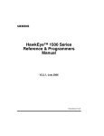
FIGURE 1–1.
HawkEye™ 1515
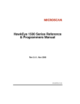
FIGURE 1–2.
HawkEye™ 1525
HawkEye™ 1500 Series User Manual
v2.2.1, July 2006
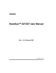
FIGURE 1–3.
HawkEye™ 1510
Both the HawkEye™ 1515 and HawkEye™ 1525 have fixed optics and
illumination built right into the units. The HawkEye™ 1510 allows you to select
from a variety of off-the-shelf optics and illumination components. For complete
information about the HawkEye™ 1510, see Appendix A, “HawkEye™ 1510”.
The HawkEye™ 1515 and HawkEye™ 1525 use the same lenses, which give the
units a range of magnifications. The HawkEye™ 1515 and HawkEye™ 1525 use
different illumination components.
Use the following paragraphs to help you pick the correct model and
magnification for your Data Matrix or Barcode reading application.
Data Matrix Construction
A Data Matrix is made up of four major components, as shown in Figure 1–4.
FIGURE 1–4.
Solid Border
Quiet Zone
v2.2.1, July 2006
1
Configurations
Selecting the Correct HawkEye™ to Read Your Data Matrix
Four Major Components of a Data Matrix
Timing Border
Data Storage
HawkEye™ 1500 Series User Manual
1-3
Chapter
1
Configurations
Selection Criteria
There are three main considerations for choosing the proper HawkEye™ type:
•
Resolution
•
Field of View
•
Working Distance
The most important consideration is Resolution. All three of these features are
governed by lens selection.
Resolution
A Data Matrix is comprised of a series of dark and light cells. To obtain optimal
READ performance, each cell should be imaged by at least 4 to 5 camera pixels.
To obtain optimal VERIFICATION performance, each cell should be imaged by
at least 10 camera pixels.
A Barcode is comprised of a series of light and dark lines. To obtain optimal
READ performance, each line should be seen as at least 2 pixels wide.
Field of View
A second and interrelated consideration is Field of View. The field of view
should be small enough for the Data Matrix to have at least 4 pixels per cell
resolution. At the same time, the field of view should be large enough to contain
the Data Matrix or Barcode, as well as to leave enough space around the symbol
to compensate for symbol positioning error and the required Quiet Zone.
Note: The Quiet Zone must be at least 1 cell in size. A Quiet Zone of 2 cells or
more is allowed, and makes reading easier.
Working Distance
The Working Distance is the distance from the front of the light to the symbol.
Typically, it is dictated by whatever clearance is required for part handling
between the HawkEye™ 1500 camera and the part. These standoff distances
vary from a low of 3 inches (76.2mm) to a high of 5 inches (127mm) with the
HawkEye™ 1515 and the HawkEye™ 1525. If you have different standoff
distance requirements, the HawkEye™ 1510 camera should be used.
1-4
HawkEye™ 1500 Series User Manual
v2.2.1, July 2006
Selecting A Lens
Standard Lens Selection Chart
Table 1–1 shows the different magnifications for the HawkEye™ 1515 and
HawkEye™ 1525 with built in lenses. Each type has a specific Working
Distance, Field of View, and Minimum Cell Size. To determine the correct type:
1.
Determine the Cell Size for your Data Matrix. Do this by measuring the size
of your Data Matrix in the horizontal direction, and by counting the number
of cells in the horizontal direction.
Cell Size = Matrix Size (H) / Number of Cells (H)
2.
Determine the overall field of view required to contain the Data Matrix,
Quiet Zone, and to allow for the positioning of the symbol.
3.
Look in the chart to see which types have a Minimum Cell Sizes less than
your cell size.
Example: Assume a Data Matrix has 23 cells in the horizontal direction, is
0.75” (19.05mm) wide, and with a quiet zone, is over 1.125” (28.58mm)
wide.
0.75” (19.05mm)
Cell Size =
---------------------
= 0.033” (0.84mm)
23
The only HawkEye™ Type that has a Minimum Cell Size less than 0.033”
(0.84mm) and a field of view greater than 1.125” (28.58mm) is the Medium
Density (MD).
v2.2.1, July 2006
HawkEye™ 1500 Series User Manual
1-5
1
Configurations
Selecting the Correct HawkEye™ to Read Your Data Matrix
Chapter
1
Configurations
TABLE 1–1. Lens
Selection Chart
Working
Distance
Field of View
at Focus
Minimum Cell Size
(4 Pixels/Cell)
Medium Density (MD)
5.0” (127mm)
± 1.0” (25.4mm)
1.55”H
(39.37mm) x
1.19”V
(30.23mm)
DM: 0.010” (0.25mm)
BC: 0.005” (0.127mm)
High Density (HD)
3.0” (76.2mm)
± 0.5” (12.7mm)
1.00”H (25.4mm)
x 0.75”V
(19.05mm)
DM: 0.006” (0.152mm)
BC: 0.003” (0.076mm)
Long High Density
(LHD)
5.0” (127mm)
± 0.5” (12.7mm)
1.00”H (25.4mm)
x 0.75”V
(19.05mm)
DM: 0.006” (0.152mm)
BC: 0.003” (0.076mm)
Super High Density
(SHD)
3.5” (88.9mm)
± 0.5” (12.7mm)
0.55”H
(13.97mm) x
0.42”V
(10.67mm)
DM: 0.003” (0.076mm)
BC: 0.0015” (0.038mm)
Ultra High Density
(UHD)
2.25” (57.15mm)
± 0.125”
(3.175mm)
0.25”H (6.35mm)
x 0.19”V
(4.83mm)
DM: 0.0013” (0.033mm)
BC: 0.0005” (0.0127mm)
Type
Custom Lens Selection
In addition to the HawkEye™ 1515 and HawkEye™ 1525 cameras with built in
lenses, the HawkEye™ 1510 is sold with a C or CS mount that allows the use of
conventional lenses. The use of conventional lenses and extension tubes allow a
much larger range of ‘fields of view’ and ‘working distances’ to be
accomplished. Standard lens selection criteria should be employed to select the
correct optics for your application.
Selecting Lighting
Standard Light Selection
The HawkEye™ 1515 and HawkEye™ 1525 come with built in lights and built
in lenses.
1-6
HawkEye™ 1500 Series User Manual
v2.2.1, July 2006
HawkEye™ 1515
FIGURE 1–5.
HawkEye™ 1515
116.51mm
(4.587)
57.15mm
(2.250)
111.76mm
(4.400)
28.58mm
(1.125)
88.90mm
(3.500)
22.86mm
(.900)
e
kEy
Haw
22.23mm
(.875)
TM
44.45mm
(1.750)
The HawkEye™ 1515 has a small light ring built on the front of the unit. The
ring is 1.75”H (44.45mm) x 1.25”H (31.75mm) at the center of the emission
zone. The ring is aimed in 15° to converge 3” (76.2mm) from the front on the
unit. When the unit is used perpendicular to the part, the light acts as a bright
field, high angle ring light. A second useful configuration is to angle the unit 20°
off of vertical. In this configuration, the light acts as a directional high angle
spotlight. The HawkEye™ 1515 configuration is the universal reader for the
broadest range of Data Matrix and Barcode reading applications.
Note: The HawkEye™ 1515-XL does not have lasers.
v2.2.1, July 2006
HawkEye™ 1500 Series User Manual
1
Configurations
Selecting the Correct HawkEye™ to Read Your Data Matrix
1-7
Chapter
1
Configurations
HawkEye™ 1525
FIGURE 1–6.
HawkEye™ 1525
72.14mm
(2.840)
116.51mm
(4.587)
111.76mm
(4.400)
36.07mm
(1.420)
22.86mm
(.900)
29.97mm
(1.180)
88.90mm
(3.500)
kE
Haw
ye
TM
59.94mm
(2.360)
6.35mm
(.250)
9.52mm
(.375)
OPTIONAL MOUNTING BLOCK
The HawkEye™ 1525 has a medium size light ring built on the front of the unit.
The ring is 2.375”H (60.33mm) x 1.875”H (47.63mm) at the center of the
emission zone. The ring is aimed in 25° to converge 2.25” (57.15mm) from the
front on the unit. When the unit is used perpendicular to the part, the light acts as
a dark field, medium to low angle ring light. Typically, the HawkEye™ 1525 is
used for highly reflective parts.
Note: The HawkEye™ 1525-XL does not have lasers.
HawkEye™ XL details
The HawkEye™ XL is designed for applications requiring ease of integration
utilizing fixed optics and integrated lighting but does not need features/benefits
provided by laser targeting.
1-8
HawkEye™ 1500 Series User Manual
v2.2.1, July 2006
Custom Light Selection
HawkEye™ 1510
FIGURE 1–7.
HawkEye™ 1510
98.73mm
(3.887)
57.15mm
(2.250)
93.98mm
(3.700)
28.58mm
(1.125)
5.08mm
(.200)
e
kEy
Haw
22.23mm
(.875)
TM
44.45mm
(1.750)
The HawkEye™ 1510 is designed for applications requiring flexibility in the
selection of lighting and optics. The unit is designed with a mounting block that
allows the attachment of C and CS mount lenses. Additionally, it has brackets
specially designed to mount a variety of the standard NER Lights. For complete
information about the HawkEye™ 1510, see Appendix A, “HawkEye™ 1510”.
Note: The HawkEye™ 1510 does not have a laser.
v2.2.1, July 2006
HawkEye™ 1500 Series User Manual
1
Configurations
Selecting the Correct HawkEye™ to Read Your Data Matrix
1-9
Chapter
1-10
1
Configurations
HawkEye™ 1500 Series User Manual
v2.2.1, July 2006
2
Connecting to the HawkEye™
1500
CHAPTER 2
The chapter contains information to help you connect to the HawkEye™ 1500
camera. Specific information describes connectors, adapters, cables, pinouts, and
signals.
Note: There are no user serviceable parts inside.
Connectivity
TCP/IP Port
When communicating over Ethernet, the camera uses the following predefined
ports. The camera establishes connections as a Server and, therefore, listens for
Host clients to initiate the connection on a particular port. Any number of clients
can connect to the camera, each one with their private peer-to-peer connection.
v2.2.1, July 2006
HawkEye™ 1500 Series User Manual
2-1
Connecting to the
HawkEye™ 1500
2
Chapter
2
Connecting to the HawkEye™ 1500
TABLE 2–1. HawkEye™
1500 TCP/IP Connectivity
Port Name
Protocol
Number
Note
Camera Query Port
UDP
49093
Discovers HawkEye™ 1500 cameras on the
current subnet.
camera Announce
Port
UDP
49094
Broadcasts the HawkEye™ 1500 camera identity
on the current subnet used by Network View in
ReadRunner, provides general counters, camera
name, IP, IP in control, camera status, and
camera software version and capability.
COMMAND
TCP
49095
Used for all HawkEye™ 1500 ASCII Commands
including accessing Buffered cycle read reports
(PARTQ commands).
STANDARD
SERIAL
N/A
Programs the format of the data sent via the serial
port.
STANDARD
TCP
49096
Used by ReadRunner and programming COM
object library for reports with images. By default
lossy up to 2 per second. Connection can be
programmed to lossless, i.e. inline with the read
cycle.
STANDARD
TCP
49097
Used by ReadRunner and programming COM
object library for reports only. By default lossy but
at maximum network rate. Connection can be
programmed to lossless, i.e. inline with the read
cycle.
TCP1 User
Connection
TCP
49098
User format configurable TCP based connection.
Uses ASCII and binary tags (IDxx), (CDxx), etc….
Note that the connection is always lossless, i.e.
inline with the read cycle.
TCP2 User
Connection
TCP
49099
User format configurable TCP based connection.
Uses ASCII and binary tags (IDxx), (CDxx), etc…
Note that the connection is always lossless, i.e.
inline with the read cycle.
TCP3 User
Connection
TCP
49100
User format configurable TCP based connection.
Uses ASCII and binary tags (IDxx), (CDxx), etc…
Note that the connection is always lossless, i.e.
inline with the read cycle.
TCP4 User
Connection
TCP
49101
User format configurable TCP based connection.
Uses ASCII and binary tags (IDxx), (CDxx), etc…
Note: Ports COMMAND, TCP1…4 use a protocol that is either ASCII or defined
by you at connection time. Therefore, these ports are fully supported on a non-
2-2
HawkEye™ 1500 Series User Manual
v2.2.1, July 2006
Connectivity
Serial Port
When communicating over a serial line, you need to be aware of the limitations
of this communication medium and how ReadRunner and the camera handle it.
There can be only one client connected to the camera. In addition, there can be
only one channel to exchange data, i.e., commands and binary data.
The ReadRunner UI enables a special ACK scheme that may need to be disabled
once the camera has been programmed and is connected serially to a PLC or the
controlling host. You can accomplish this by sending special control characters
(see Table 2–2):
TABLE 2–2. Serial
Port Connectivity
Control Char
Function
Ctrl+O
Turn off report output.
Ctrl+P
Toggle the state of the prompt and echo.
Ctrl+Q
Turn off command output.
Ctrl+R
Release control of the unit and put it back online.
Ctrl+S
Take control of the unit and bring it offline (forcibly).
Ctrl+T
Dump the heartbeat string to the terminal.
Ctrl+U
Toggle the display of report strings on the terminal.
Ctrl+W
Turn on command output.
If the Serial port is programmed for 7 bits per character, certain features of the
ReadRunner UI are not supported; in particular, “Hook Reports” and “Hook
Images” are not available, as they transfer image and counters (binary data) and
cannot be represented using a 7 bit per character ASCII format.
Notes: Regardless of whether the 7 or 8 bits per character are programmed,
“Hook Reports” and “Hook Images” must be disconnected before quitting the
ReadRunner application before connecting the camera over serial to the
controlling device.
v2.2.1, July 2006
HawkEye™ 1500 Series User Manual
2-3
2
Connecting to the
HawkEye™ 1500
Windows based Host, provided the Host supports TCP/IP and a socket level API.
Ports 49096 and 49097 use a binary format that is parsed into easy to use COM
events and objects on the Host and is, therefore, only applicable to Windowsbased Hosts.
Chapter
2
Connecting to the HawkEye™ 1500
Output formatting settings for the serial port are available in ReadRunner under
the STANDARD Tab in the Output Settings Form.
Rear Panel
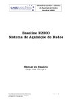
Figure 2–1 details the layout of the rear panel.
FIGURE 2–1.
Rear Panel Layout
Power Connector
Ethernet Connector
Power ON LED
Ethernet LINK LED
Ethernet ACT LED
2-4
Field I/O Connector
I/O
DC-IN
RS-232
ETHERNET
PWR
Serial Port Connector
LK
ACT
QuicSet
QuicSet Switch
•
Power Connector – 24VDC in
•
Field I/O Connector – DB15S – 1 Opto in, 3 Opto Out, 4 GPIO (strobe out
optional on GPIO 1)
•
Serial Port Connector – 8 pin mini-DIN
•
Ethernet Connector – RJ45
•
Ethernet LINK LED – Green
•
Ethernet ACT LED – Yellow
•
Power ON LED – Green
•
QuicSet Switch – Recessed
HawkEye™ 1500 Series User Manual
v2.2.1, July 2006
Power Connector
Power Connector
Figure 2–2 shows the pinout of the Power connector.
2
Power Connector Pinout
3
Connecting to the
HawkEye™ 1500
FIGURE 2–2.
2
1
Table 2–3 lists the suppliers for the power connector mating connector.
TABLE 2–3. Power
Connector Mating Connector Suppliers
Supplier
Part Number
Description
Siemens
HECONNPS
Housing and socket crimp Kit
HIROSE
RP34-8SP-3SC
RP34-SC-112
Housing
Socket crimp
Table 2–4 describes the power connector signals.
TABLE 2–4. Power
v2.2.1, July 2006
Connector Signals
Pin
Signal Name
1
Chassis ground
2
+24 VDC
3
24V return
HawkEye™ 1500 Series User Manual
2-5
Chapter
2
Connecting to the HawkEye™ 1500
Power Supply Wiring
Figure 2–3 and Figure 2–4 show the wiring for the power supply.
FIGURE 2–3.
Power Supplied Via the HEPS-1500 Wall Mount Power Supply
HEPS-1500 Power Supply
Camera
FERRITE
BEAD
+24 VDC
+24 VDC
GND
GND
CHASSIS GND
CHASSIS GND
Note: Ferrite suppression bead is integrated on power supply cable.
TABLE 2–5. Power
2-6
Supply Suppliers
Supplier
Part Number
Description
Siemens
HEPS-1500
Wall mount power supply
HawkEye™ 1500 Series User Manual
v2.2.1, July 2006
Power Supply Wiring
FIGURE 2–4.
Power Supplied Via a User Supplied Source
2
+24 VDC
Connecting to the
HawkEye™ 1500
FERRITE
BEAD
+24 VDC
GND
GND
CHASSIS GND
CHASSIS GND
Note: Ferrite suppression bead is required to meet CE radiated emission
requirements.
TABLE 2–6. Power
v2.2.1, July 2006
Cable and Ferrite Bead Suppliers
Suppliers
Part Number
Description
Siemens
HEPC-006
Single-ended power cable - 6 Ft.
w/molded ferrite bead
Siemens
914-0012-1
EMI Round Cable Suppression Core
Fair-Rite
0443167251
HawkEye™ 1500 Series User Manual
2-7
Chapter
2
Connecting to the HawkEye™ 1500
Field I/O Connector
Figure 2–5 shows the pinout for the HDB-15S connector.
FIGURE 2–5.
Field I/O (HDB-15S) Connector
11
6
15
10
1
5
Table 2–7 lists the suppliers for the field I/O (HDB-15S) mating connector.
TABLE 2–7. Field
I/O (HDB-15S) Mating Connector Suppliers
Supplier
Part Number
Description
Siemens
HECONNIO
Housing and Hood Kit
AMP
748676-1
Housing
HEIL
180-015-102-001
Hood
Table 2–8 describes the field I/O signals.
TABLE 2–8. Field
I/O Signals
S/W
Direction
Pin
Signal
Direction
H/W Description
6
sensor power
out
Fused +24V, 100 ma
max.
1
10
sensor power
return
common
DC ground
1
1
opto in a
in
Trigger input A
In
OPTO IN 1
2,6
11
opto in b
in
Trigger input B
In
OPTO IN 1
2,6
2
opto 1 out a
out
Pass output a
out
OPTO OUT
PASS
3,7
12
opto 1 out b
out
Pass output b
out
OPTO OUT
PASS
3,7
3
opto 2 out a
out
Fail output a
out
OPTO OUT FAIL
3,8
13
opto 2 out b
out
Fail output b
out
OPTO OUT FAIL
3,8
4
opto 3 out a
out
Data valid a
out
OPTO OUT DV
3,9
2-8
HawkEye™ 1500 Series User Manual
S/W Name
Notes
v2.2.1, July 2006
Field I/O Connector
I/O Signals (Continued)
2
14
opto 3 out b
out
Data valid b
out
OPTO OUT DV
3,9
5
TTL IO 1 /
Ext. strobe
In/out
General purpose I/O
1/ external strobe 1
out
LIGHTING
EXTERNAL
4,5,
10
7
TTL IO 2
In/out
General purpose I/O 2
out
NOT USED
5
8
TTL IO 3
In/out
General purpose I/O 3
out
RTE OUT
5,11
9
TTL IO 4
In/out
General purpose I/O 4
in
GPIO IN 4
DURATION
5,12
15
I/O return
common
DC ground
shell
chassis
ground
Notes:
1.
Non-isolated utility power for sensor and/or opto current loops.
2.
Bipolar isolated current input 5-24V, 1-5 ma., 250VAC isolation.
3.
Bipolar isolated output switch, Ron = 35 ohm max., Ion < 50 ma, Voff <
50VDC, 250VAC isolation.
4.
4V, 20 ma positive pulse in strobe mode.
5.
OUT: 20 ma sink, 2.2K to +5V pullup. IN: TTL, 1V hysteresis.
6.
Opto-isolated camera sensor trigger.
Note: Notes 7 through 12 refer to default I/O assignment. This may change
according to user assignment.
v2.2.1, July 2006
7.
Read Pass signal for I/O Pass/Fail modes. Read Pass/Fail for I/O Data Valid
modes.
8.
Read Fail signal; either decode, locate or match fail for I/O Pass/Fail modes.
Not used for I/O Data Valid modes.
9.
Data Valid signal used in all pipelined I/O modes. External equipment can
read result of decode while this signal is asserted.
10.
Controls the external strobe light. Set in Application mode -> Lighting.
HawkEye™ 1500 Series User Manual
2-9
Connecting to the
HawkEye™ 1500
TABLE 2–8. Field
Chapter
2
Connecting to the HawkEye™ 1500
11.
Runtime Error signal: programmed to assert when Trigger, Read, Timeout
Overruns and/or Network drops occur.
12.
Used by StopAndScan to signal retry duration.
Figure 2–6 shows the Opto In equivalent circuit.
FIGURE 2–6.
Opto In
+3.3V
R
15K
R
OPTO_IN_A
2.2K
R
10K
R
OPTO_IN_B
D
2.2K
Figure 2–7 shows the Opto Out equivalent circuit.
FIGURE 2–7.
+3.3V
Opto Out
330
OPTO_OUT_XA
OPTO_OUT_XB
2-10
HawkEye™ 1500 Series User Manual
v2.2.1, July 2006
Grounding Tab (Optional)
Figure 2–8 shows the TTL I/O equivalent circuit.
2
TTL I/O
R
10K
+5V
R
2.2K
R
TTLIOX
C
3300PF
10
+5V
+3.3V
IOGND
+3.3V
IOGND
IO
Grounding Tab (Optional)
Normally, the HawkEye™ 1500 chassis is connected to ground via the serial
cable or the I/O interface cable shield (assuming that the cable shield is
connected to ground). If not, a Grounding tab kit is available for the HawkEye™
1500 reader. The kit provides two grounding tabs, a Solder tab, and a 0.187
Faston tab that gets mounted to one of the HDB-15 hex standoffs (see
Figure 2–9).
v2.2.1, July 2006
HawkEye™ 1500 Series User Manual
2-11
Connecting to the
HawkEye™ 1500
FIGURE 2–8.
Chapter
2
Connecting to the HawkEye™ 1500
FIGURE 2–9.
Grounding Tab Mounting Location
I/O
DC-IN
.187 Faston Tab
RS-232
ETHERNET
PWR
LK
ACT
QuicSet
Solder Tab
Table 2–9 lists the Grounding tab part numbers and descriptions for the
HawkEye™ 1500.
TABLE 2–9. Grounding
Tab Part Numbers
Part Number
Description
A1-40201-1
HawkEye™ Grounding Tab Kit – includes:
958-0039-1
0.187 Faston tab with 45 bend
958-0040-4
Solder tab with 45 bend
Use the following steps to install the grounding tab:
2-12
1.
Remove one of the HDB-15 standoffs using a 3/16” Hex Driver.
2.
Install the grounding tab (either Solder or Faston type) and standoff as
shown in Figure 2–9.
3.
Tighten the standoff.
HawkEye™ 1500 Series User Manual
v2.2.1, July 2006
I/O Expansion Module (Optional)
I/O Expansion Module (Optional)
•
All of the I/O connections from the camera to the I/O Expansion Module are
connected via a 15-pin cable.
•
One opto-isolated camera sensor input trigger is provided. The sensor input
requires a bipolar isolated current input 5-24VDC at 1-5mA.
•
Three opto-isolated outputs are provided. The outputs are bipolar isolated
switches, Ron = 35 ohms max, Ion < 50ma., Voff <= 50VDC.
•
Four digital I/O ports are provided (General Purpose I/O 1 - 4). The digital
I/O ports are individually programmable as inputs or outputs from the
camera using Opto 22™ G4-type isolator modules.
•
General Purpose I/O 1 is also used to optionally control an external strobe
light. Jumper, JMP1, is provided to select the strobe output or the isolator
module.
•
The board is provided with a Din-Rail mount.
Figure 2–10 shows the I/O expansion module.
v2.2.1, July 2006
HawkEye™ 1500 Series User Manual
2-13
2
Connecting to the
HawkEye™ 1500
The I/O Expansion Module provides a convenient method of connecting to the
HawkEye™ camera I/O signals. It combines one dedicated optically isolated
sensor input, three dedicated optically isolated outputs, and four digital I/O ports
all on one circuit board, as shown in Figure 2–10, “I/O Expansion Module,” on
page 2-14.
Chapter
2
Connecting to the HawkEye™ 1500
FIGURE 2–10.
I/O Expansion Module
Using the I/O Expansion Module
•
Sensor Inputs — There is one sensor input. The sensor input is brought out
directly from the 15-pin HD-Sub header (J1) to barrier strip (TB1) positions
4 and 5. The camera sensor trigger input is a bipolar isolated current input,
and is located within the camera.
A chassis ground connection is provided on terminal block “TB1” position 1
and is used for connecting the sensor cable shield to chassis ground.
2-14
•
Opto Outputs — There are three opto outputs. The opto outputs are brought
out directly from the 15-pin HD-Sub header (J1) to barrier strip (TB1)
positions 6 through 11. The opto-isolated outputs represent the camera’s
output signals. These signals are bipolar isolated output switches, and are
located within the camera.
•
General Purpose I/O — Four positions are available for industry-standard
Opto 22™ G4 type input or output isolator modules. The field wiring to
HawkEye™ 1500 Series User Manual
v2.2.1, July 2006
I/O Expansion Module (Optional)
Jumper (JMP1) must be set to positions 2&3 to use General Purpose I/O 1.
Notes: Setting JMP1 to positions 2&3 will disable the “Strobe” output.
In this position, the camera must not be set to External Strobe mode; refer to
the camera’s user manual to set the camera illumination mode to something
other than External Strobe mode.
+24 volts DC power (fused @ 100mA) is brought out directly from the
15-pin HD-Sub header (J1) to barrier strip (TB1) position 1. Internal +5
volts DC is generated from the 24 volt DC source and provides logic power
to the 4 General Purpose I/O Optos IO1 through IO4.
The Smart Camera I/O board accepts only 5-volt-logic solid-state relays
(Opto 22™ G4-type isolator modules).
Note: There is no connector for connecting external isolator module power
(5 volts).
•
Strobe — The external strobe output is a TTL signal from the camera that
connects to the barrier strip (TB1) position 12 (STROBE) via the 15-pin
HD-Sub header (J1) and jumper (JMP1). The strobe output signal has an inline Lo-Pass filter with a 2Mhz cutoff. There is a Strobe LED (STRB) that
indicates whenever the strobe signal is ON (high).
Jumper (JMP1) must be set to positions 1&2 to use the strobe output.
Notes: Setting JMP1 to positions 1&2 will disable General Purpose I/O 1.
To use External Strobe, the camera must be set to External Strobe
illumination mode; refer to either of the following:
v2.2.1, July 2006
HawkEye™ 1500 Series User Manual
2-15
2
Connecting to the
HawkEye™ 1500
these modules is terminated on the barrier strip TB2. General Purpose I/O
ports (isolator modules) 1 through 4 may be configured as either inputs or
outputs. The TTL I/O signals from the camera enter via the 15-pin HD-Sub
header (J1) on positions 5, 7, 8, & 9 corresponding to General Purpose I/O
points 1 through 4. The TTL I/O signals are filtered with EMI “T” filters.
There are four LED's that indicate whenever the TTL I/O signals are ON
(low). The LED's operate whether or not an isolator module is plugged in.
Chapter
2
Connecting to the HawkEye™ 1500
Chapter 4 of this manual.
The ILLUMINATION command in the HawkEye™ 1500 Series Reference &
Programmers Manual.
•
Spare Fuse & 5VOK LED — There is a spare fuse in the spare fuse socket
which doubles as a fuse/+5 volt OK test circuit. When the green LED
(5VOK) is ON it indicates that both +5 volts and the fuse are OK.
Note: There is no connector for connecting external 5 volts.
Table 2–10 lists the part numbers for the Smart Camera I/O board and interface
cables.
TABLE 2–10. I/O
Expansion Module Suppliers
Part Number
Description
003-406000
I/O Expansion Module - includes:
966-0183-1
Cable HD-Sub 15 connector M/M 10 Feet
Optional Cables
966-0183-2
Cable HD-Sub 15 connector M/M 15 Feet
966-0183-3
Cable HD-Sub 15 connector M/M 25 Feet
I/O Expansion Module Connectors
I/O Interface Connector – J1
Figure 2–11 shows the pinout for the HDB-15S connector.
FIGURE 2–11.
2-16
Field I/O (HDB-15S) Connector
11
6
15
10
1
5
HawkEye™ 1500 Series User Manual
v2.2.1, July 2006
I/O Expansion Module (Optional)
I/O Interface Connector — J1
Pin
Description
1
Sensor Input A
2
Opto Output 1 A
3
Opto Output 2 A
4
Opto Output 3 A
5
General Purpose I/O 1 or Strobe
6
+24 volts
7
General Purpose I/O 2
8
General Purpose I/O 3
9
General Purpose I/O 4
10
24 volt return (Ground)
11
Sensor Input B
12
Opto Output 1 B
13
Opto Output 2 B
14
Opto Output 3 B
15
I/O Return (Ground)
Shell
Chassis Ground
2
Connecting to the
HawkEye™ 1500
TABLE 2–11. Pinout
Opto In, Opto Out, & Strobe Output Terminal Block – TB1
Figure 2–12 shows the I/O expansion module TB1.
v2.2.1, July 2006
HawkEye™ 1500 Series User Manual
2-17
Chapter
2
Connecting to the HawkEye™ 1500
FIGURE 2–12.
I/O Expansion Module — TB1
TB1
2
+24 volts
4
Sensor Input A
6
Opto Output 1 A
8
Opto Output 2 A
10
Opto Output 3 A
12
Strobe Output
14
Ground
TABLE 2–12. Pinout
2-18
1
Chassis Ground
3
Ground
5
Sensor Input B
7
Opto Output 1 B
9
Opto Output 2 B
11
Opto Output 3 B
13
Ground
Opto In, Opto Out & Strobe Terminal Block — TB1
Pin
Description
1
Chassis Ground
2
+24 volts
3
24 volt return (Ground)
4
Sensor Input A (Trigger)
5
Sensor Input B (Trigger)
6
Opto Output 1 A
7
Opto Output 1 B
8
Opto Output 2 A
9
Opto Output 2 B
10
Opto Output 3 A
HawkEye™ 1500 Series User Manual
v2.2.1, July 2006
I/O Expansion Module (Optional)
TABLE 2–12. Pinout
Opto In, Opto Out & Strobe Terminal Block — TB1
(Continued)
Opto Output 3 B
12
Strobe
13
Strobe Return (Ground)
14
Ground
2
Connecting to the
HawkEye™ 1500
11
General Purpose I/O Terminal Block – TB2
Figure 2–13 shows the I/O expansion module TB2.
FIGURE 2–13.
Opto 1
Opto 2
Opto 3
Opto 4
v2.2.1, July 2006
I/O Expansion Module — TB2
1 +
2
-
3 +
4
-
5 +
6
-
7 +
8
-
HawkEye™ 1500 Series User Manual
2-19
Chapter
2
Connecting to the HawkEye™ 1500
TABLE 2–13. Pinout
General Purpose I/O Terminal Block — TB2
Pin
Description
1
G.P. Opto 1 Positive (+) Terminal
2
G.P. Opto 1 Negative (-) Terminal
3
G.P. Opto 2 Positive (+) Terminal
4
G.P. Opto 2 Negative (-) Terminal
5
G.P. Opto 3 Positive (+) Terminal
6
G.P. Opto 3 Negative (-) Terminal
7
G.P. Opto 4 Positive (+) Terminal
8
G.P. Opto 4 Negative (-) Terminal
Field I/O Wiring Examples
Input Opto Wiring
Sample wiring diagrams for trigger input A and B (opto input) are located on
terminal block TB1 positions 4 and 5 (see Figure 2–14 and Figure 2–15).
FIGURE 2–14.
NPN Source
+5-24V
Input Opto Wiring (Isolated NPN and PNP Sources)
PNP Source
Camera
Vcc
Camera
+5-24V
Signal
Vcc
Signal
2-20
HawkEye™ 1500 Series User Manual
v2.2.1, July 2006
I/O Expansion Module (Optional)
FIGURE 2–15.
NPN Source
Input Opto Wiring (Non-Isolated NPN and PNP Sources)
PNP Source
Camera
+24 VDC
Vcc
2
Camera
+24 VDC
Vcc
Connecting to the
HawkEye™ 1500
Signal
Signal
Output Opto Wiring
Sample wiring diagrams for PASS, FAIL, and DATA VALID outputs (opto
outputs 1, 2, and 3) are located on terminal block TB1 (see Figure 2–16 and
Figure 2–17):
•
PASS (opto output 1) — Positions 6 and 7
•
FAIL (opto output 2) — Positions 8 and 9
•
DATA VALID (opto output 3) — Positions 10 and 11
The assignment of PASS, FAIL, AND DATA VALID to these lines is the default
factory setting. In V2.0, other outputs can be configured to come out on the
OPTO_OUT1, OPTO_OUT2, and OPTO_OUT3 lines.
v2.2.1, July 2006
HawkEye™ 1500 Series User Manual
2-21
Chapter
2
Connecting to the HawkEye™ 1500
FIGURE 2–16.
Output Opto Wiring (Isolated Input)
<50V
<50V
Input
OR
Input
FIGURE 2–17.
Camera
Output Opto Wiring (Isolated Relay and PLC Inputs)
Relay
Camera
<50V
PLC
<50V
PLC
Input
GND
2-22
HawkEye™ 1500 Series User Manual
v2.2.1, July 2006
I/O Expansion Module (Optional)
Figure 2–18 shows the output opto wiring for non-isolated inputs.
Camera
2
Output Opto Wiring (Non-Isolated Inputs)
Host
+24 VDC
Camera
Host
+24 VDC
Input
Input
The maximum current that can pass through the optoisolators is 50 mA.
Non-isolation setup can cause damage to the HawkEye™ 1500 if excessive
voltage is applied to the optoisolators.
v2.2.1, July 2006
HawkEye™ 1500 Series User Manual
2-23
Connecting to the
HawkEye™ 1500
FIGURE 2–18.
Chapter
2
Connecting to the HawkEye™ 1500
Sample wiring diagrams for strobe output (TTL I/O 1 in strobe mode) are located
on terminal block TB1 positions 12 and 13 (GND) (see Figure 2–19 and
Figure 2–20):
FIGURE 2–19.
Equivalent Circuit of TTL IO 1 in Strobe Mode
+5V
20 ma current limit
Voh=4V
@ ioh=20 ma
10
strobe
2.2K
FIGURE 2–20.
tvs
+
filter
External DIO (TTL IO 1 Only) Wiring in Strobe Mode
Camera
User Strobe Interface
+5V
20 mA current limit
To Strobe input
(20 mA max @ 4V)
2 mA
2.2K
Note: Jumper (JMP1) must be set to positions 1 and 2 to use the strobe output.
2-24
HawkEye™ 1500 Series User Manual
v2.2.1, July 2006
I/O Expansion Module (Optional)
General Purpose I/O Wiring
Figure 2–21 shows four sample wiring diagrams for: Input AC, Output AC, Input
DC, and Output DC Opto modules on terminal block TB2.
•
Opto 1 Positions 1 & 2
•
Opto 2 Positions 3 & 4
•
Opto 3 Positions 5 & 6
•
Opto 4 Positions 7 & 8
Notes: Correct polarity is critical for DC modules. The odd-numbered terminals
on the I/O board are positive (+) and the even-numbered terminals are negative
(-).
Jumper (JMP1) must be set to positions 2 and 3 to use opto 1 (TTL I/O 1) in I/O
mode.
v2.2.1, July 2006
HawkEye™ 1500 Series User Manual
2-25
2
Connecting to the
HawkEye™ 1500
Each Opto 22™ module has two associated screw terminals. Wire them
according to the manufacturer’s recommendations and your company’s electrical
standards. Typically, one side of all input modules connect to the hot power
terminal with input devices (e.g., switches) wired between the other contact and
the common terminal. Output modules are often wired to the common terminal,
with loads returning to the hot terminal.
Chapter
2
Connecting to the HawkEye™ 1500
FIGURE 2–21.
I/O Expansion Module G4 Opto I/O Wiring Examples
L1
L1
AC
LOOP
SUPPLY
SWITCH
L2
L2
1
1
2
2
3
AC
LOOP
SUPPLY
LOAD
3
Input DC
Output AC
4
4
5
INPUT AC
USING
STANDARD
MOUNTING RACK
OUTPUT AC
USING
STANDARD
MOUNTING RACK
L1
L1
+
SWITCH
L2
-
DC
LOOP
SUPPLY
+
LOAD
L2
-
DC
LOOP
SUPPLY
+
+
1
1
2
2
3
Input DC
3
Output AC
4
4
5
INPUT AC
USING
STANDARD
MOUNTING RACK
OUTPUT AC
USING
STANDARD
MOUNTING RACK
This gives you access to a combination of up to 4 input or output modules.
2-26
HawkEye™ 1500 Series User Manual
v2.2.1, July 2006
External I/O Terminal Block Adapter (Optional)
External I/O Terminal Block Adapter (Optional)
Figure 2–22 shows the I/O external terminal block adapter.
SH
15
8
13
14
7
2
I/O External Terminal Block Adapter
6
12
5
10
11
4
3
Connecting to the
HawkEye™ 1500
FIGURE 2–22.
9
2
1
1
15
External I/O Terminal Block Connectors
I/O Interface Connector – (15 Connector HDB-Sub)
Figure 2–23 shows the pinout for the HDB-15S connector.
v2.2.1, July 2006
HawkEye™ 1500 Series User Manual
2-27
Chapter
2
Connecting to the HawkEye™ 1500
FIGURE 2–23.
Field I/O (HDB-15S) Connector
11
6
15
10
1
5
TABLE 2–14. Pinout
I/O Interface Connector (15 Position HDB-Sub)
Pin
Description
1
Sensor Input A
2
Opto Output 1 A
3
Opto Output 2 A
4
Opto Output 3 A
5
General Purpose I/O 1 or Strobe
6
+24 volts
7
General Purpose I/O 2
8
General Purpose I/O 3
9
General Purpose I/O 4
10
24 volt return (Ground)
11
Sensor Input B
12
Opto Output 1 B
13
Opto Output 2 B
14
Opto Output 3 B
15
I/O Return (Ground)
Shell
Chassis Ground
Signal Distribution Terminal Block
Figure 2–24 shows the Signal Distribution Terminal Block.
2-28
HawkEye™ 1500 Series User Manual
v2.2.1, July 2006
External I/O Terminal Block Adapter (Optional)
FIGURE 2–24.
Signal Distribution Terminal Block
Terminal Block
8
General Purpose I/O 2
7
+24 volts
General Purpose I/O 1 or Strobe
5
Opto Output 3 A
4
Opto Output 2 A
3
Opto Output 1 A
2
Sensor Input A
TABLE 2–15. Pinout
v2.2.1, July 2006
6
Chassis Ground
15
Ground
14
Opto Output 3 B
13
Opto Output 2 B
12
Opto Output 1 B
11
Sensor Input B
10
Ground
1
9
2
Connecting to the
HawkEye™ 1500
General Purpose I/O 3
SH
General Purpose I/O 4
Signal Distribution Terminal Block
Pin
Description
1
Sensor Input A
2
Opto Output 1 A
3
Opto Output 2 A
4
Opto Output 3 A
5
General Purpose I/O 1 or Strobe
6
+24 volts
7
General Purpose I/O 2
8
General Purpose I/O 3
9
General Purpose I/O 4
10
24 volt return (Ground)
11
Sensor Input B
HawkEye™ 1500 Series User Manual
2-29
Chapter
2
Connecting to the HawkEye™ 1500
TABLE 2–15. Pinout
Signal Distribution Terminal Block (Continued)
12
Opto Output 1 B
13
Opto Output 2 B
14
Opto Output 3 B
15
I/O Return (Ground)
Field I/O Wiring Examples
Input Opto Wiring
Sample wiring diagrams for trigger inputs A and B (opto inputs) are located on
terminal block TB1 positions 1 and 11 (see Figure 2–25 and Figure 2–26):
FIGURE 2–25.
NPN Source
Input Opto Wiring (Isolated NPN and PNP Sources)
PNP Source
Camera
Vcc
+5-24V
Camera
+5-24V
Vcc
Signal
Signal
FIGURE 2–26.
NPN Source
Input Opto Wiring (Non-Isolated NPN and PNP Sources)
PNP Source
Camera
+24 VDC
Camera
+24 VDC
Vcc
Vcc
Signal
Signal
2-30
HawkEye™ 1500 Series User Manual
v2.2.1, July 2006
External I/O Terminal Block Adapter (Optional)
Output Opto Wiring
Sample wiring diagrams for PASS, FAIL, and DATA VALID outputs (opto
outputs 1, 2, and 3) are located on terminal block TB1 (see Figure 2–27,
Figure 2–28 and Figure 2–29):
PASS (opto output 1) — Positions 2 and 12
•
FAIL (opto output 2) — Positions 3 and 13
•
DATA VALID (opto output 3) — Positions 4 and 14
The assignment of PASS, FAIL, AND DATA VALID to these lines is the default
factory setting. In V2.0. other outputs can be configured to come out on the
OPTO_OUT1, OPTO_OUT2, and OPTO_OUT3 lines.
FIGURE 2–27.
Camera
Output Opto Wiring (Isolated Input)
Host
Host
<50V
<50V
Input
OR
Input
v2.2.1, July 2006
HawkEye™ 1500 Series User Manual
2-31
Connecting to the
HawkEye™ 1500
•
2
Chapter
2
Connecting to the HawkEye™ 1500
FIGURE 2–28.
Camera
Output Opto Wiring (Isolated Relay and PLC Inputs)
Relay
Camera
<50V
PLC
<50V
PLC
Input
GND
FIGURE 2–29.
Camera
Output Opto Wiring (Non-Isolated Inputs)
Host
+24 VDC
Camera
Host
+24 VDC
Input
Input
The maximum current that can pass through the optoisolators is 50 mA.
Non-isolation setup can cause damage to the HawkEye™ 1500 if excessive
voltage is applied to the optoisolators.
2-32
HawkEye™ 1500 Series User Manual
v2.2.1, July 2006
External I/O Terminal Block Adapter (Optional)
TTL I/O Wiring
Sample wiring diagrams for strobe output (TTL I/O 1 in strobe mode) are located
on terminal block positions 5 and 15 (GND) (see Figure 2–30 and Figure 2–31):
Connecting to the
HawkEye™ 1500
Equivalent Circuit of TTL IO 1 in Strobe Mode
FIGURE 2–30.
+5V
20 ma current limit
Voh=4V
@ ioh=20 ma
10
strobe
2.2K
tvs
+
filter
Figure 2–31 shows the equivalent DIO wiring in strobe mode.
External DIO (TTl IO 1 Only) Wiring in Strobe Mode
FIGURE 2–31.
Camera
User Strobe Interface
+5V
20 mA current limit
To Strobe input
(20 mA max @ 4V)
2 mA
2.2K
Sample wiring diagrams for external TTL I/O (including TTL I/O 1 in I/O mode)
are located on the terminal block:
•
v2.2.1, July 2006
TTL I/O 1 Position 5
HawkEye™ 1500 Series User Manual
2
2-33
Chapter
2
Connecting to the HawkEye™ 1500
•
TTL I/O 2 Position 7
•
TTL I/O 3 Position 8
•
TTL I/O 4 Position 9
See Figure 2–32 and Figure 2–33.
FIGURE 2–32.
Equiv. Circuit of TTL I/Os (including TTL IO 1 in I/O Mode)
+5V
Vol = 0.55V max
@ iol = -24ma
2.2K (IO2, 3, 4)
3.2K (IO1)
OUT
10
IN
tvs
+
filter
Vih = 2V min
Vil = 1V max
Vhyst = 1V
FIGURE 2–33.
External DIO Wiring in I/O Mode
Camera
User TTL Interface
+5V
2.2K
2-34
To TTL input or output
(20 mA sink max)
HawkEye™ 1500 Series User Manual
v2.2.1, July 2006
External I/O Terminal Block Adapter Cable (Optional)
External I/O Terminal Block Adapter Cable (Optional)
FIGURE 2–34.
External I/O Adapter Cable
CABLE SHIELD
1
2
3
4
5
6
7
8
9
10
11
12
13
14
15
1
2
3
4
5
6
7
8
9
10
11
12
13
14
15
HDB-15M
WIRE = 26AWG
L
'CONN DETAIL'
'CONN DETAIL'
5
10
15
5
10
15
1
6
11
HDB-15M PIN OUT
HDB-15M PIN OUT
v2.2.1, July 2006
1
6
11
HawkEye™ 1500 Series User Manual
2-35
2
Connecting to the
HawkEye™ 1500
Figure 2–34 shows the wiring for the external I/O terminal block adapter cable.
Chapter
2
Connecting to the HawkEye™ 1500
Table 2–16 shows the part numbers for the terminal block adapter and cables.
TABLE 2–16. I/O
Terminal Block Adapter & Cable Part Numbers
Siemens
P/N
Description
990-0056-1
Adapter, HD-SUB 15 connector to terminal block
966-0183-1
Cable HD-SUB 15 connector M/M 10 Feet
966-0183-2
Cable HD-SUB 15 connector M/M 15 Feet
966-0183-3
Cable HD-SUB 15 connector M/M 25 Feet
External Strobe & Sensor
For continuous motion or high-speed indexing applications, an external strobe
and sensor may be required to freeze each part before the image can be acquired.
The strobe unit may include a fiber-optic light pipe.
When choosing your part sensor, you must consider the time interval between the
part passing into the sensing zone and an electrical signal being generated. When
there is a large variation in process speed, considerable apparent motion of the
part within the FOV may result. The HawkEye™ 1500 can compensate for this
motion over a considerable range. However, the sensor should be fast enough to
minimize this apparent shift.
To connect your sensor and strobe, refer to Figure 2–35 and Figure 2–36.
Figure 2–35 shows the I/O Expansion Module Sensor and Strobe Connections
shown with a fiber-optic sensor, an SCM-1 strobe controller, and a 24 volt power
supply.
2-36
HawkEye™ 1500 Series User Manual
v2.2.1, July 2006
External Strobe & Sensor
FIGURE 2–35.
I/O Expansion Module Sensor and Strobe Connections
2
Blue
Sh
ield
Brown
Connecting to the
HawkEye™ 1500
Jumper
Sensor Cable
White (Sink)
Flash+
Strobe Cable
Flash-
Sensor
SM312
To Strobe Light
AS-MP50-xxx (Assy.)
Eye
Hawk
SCM-1
TM
966-0183-1
Hawkeye 1510
030-008400
030-008800
I/O Expansion Module
003-406000
24 Volt
Power Supply
SCM-1 Strobe Controller 24 Volt Power Supply
010-502702
010-502601 or
010-502602
Figure 2–36 shows the I/O Terminal Block Adapter Sensor and Strobe
Connections shown with a fiber-optic sensor, an SCM-1 strobe controller, and a
24 volt power supply.
v2.2.1, July 2006
HawkEye™ 1500 Series User Manual
2-37
Chapter
2
Connecting to the HawkEye™ 1500
FIGURE 2–36.
I/O Terminal Block Adapter Sensor & Strobe Connections
SH
Blue
8
15
7
24 RTN
STROBE
5
13
6
14
+24
Sensor Cable
SHIELD
2
4
11
3
SENSEB
10
2
GND
Brown
k)
(Sin
ite
Wh
Sh
iel
d
Flash
+
Flash-
Strobe Cable
9
1
SENSEA
Jumper
Sensor
SM312
To Strobe Light
AS-MP50-xxx (Assy.)
SCM-1
SH
8
15
7
14
TM
6
13
5
12
Eye
Hawk
4
11
2
9
1
2-38
10
Hawkeye 1510
3
966-0183-1
030-008400
030-008800
I/O Terminal Block Adapter
990-0056-1
SCM-1 Strobe Controller
010-502702
HawkEye™ 1500 Series User Manual
24 Volt
Power Supply
24 Volt Power Supply
010-502601 or
010-502602
v2.2.1, July 2006
Serial Connector & Serial Adapter Cable
Serial Connector & Serial Adapter Cable
Figure 2–37 shows the pinout for the mini-DIN 8 serial cable.
7
5
6
4
2
Connecting to the
HawkEye™ 1500
8
2
Serial Connector (mini-DIN 8)
FIGURE 2–37.
3
1
Table 2–17 lists the suppliers for the mini-DIN 8 mating connector.
TABLE 2–17. mini-DIN
8 Mating Connector Suppliers
Supplier
Part Number
Description
Kycon
KDMLA-8P-G30
Mini-DIN Plug - 8 Position Snap and
Lock Kit
Figure 2–38 shows the wiring for the HESC-006 serial adapter cable.
v2.2.1, July 2006
HawkEye™ 1500 Series User Manual
2-39
Chapter
2
Connecting to the HawkEye™ 1500
FIGURE 2–38.
HESC-006 Serial Adapter Cable
KDMLA-8P
KYCON MINI DIN-8
CABLE SHIELD
NC
NC
GRAY
BLUE
YELLOW
RED
NC
NC
1
2
3
4
5
6
7
8
NC
NC
NC
NC
GRAY
BLUE
YELLOW
RED
BROWN
1
4
6
9
2
3
8
7
5
DB-9F
HOST CPU
CONNECT SHIELD TO
CONNECTOR SHELL
WIRE = 28AWG
72 INCHES
8.00
4 INCHES
OVER-MOLD
P/N
REV.
KDMLA-8P
KYCON MINI DIN-8
FAIR-RITE
2643540002
'CONN DETAIL'
8
7
2
5
1
6
3
4
5
'CONN DETAIL'
6
1
9
DB-9F PIN OUT
SOLDER SIDE
SOLDER SIDE
2-40
HawkEye™ 1500 Series User Manual
v2.2.1, July 2006
Ethernet
Table 2–18 describes the signals for the serial connector and serial cable.
1
Connector (mini-DIN 8), Serial Adapter Cable (DB9S)
DB9 Pin
Mini-DIN 8 Pin
RS232 Signal
Direction
Description
1
n/c
DCD
n/u
Carrier detect
2
3
TXD
out
Transmit data
3
4
RXD
in
Receive data
4
n/c
DTR
n/u
Data terminal ready
5
7, 8
Gnd
Common
Signal ground
6
n/c
DSR
n/u
Data set ready
7
6
CTS
in
Clear to send
8
5
RTS
out
Ready to send
9
n/c
RI
n/u
Ring indicator
Shell
Shell
Shell
Common
Chassis ground
Note:
1.
Mini-DIN 8 pins 1 & 2 are not connected.
Ethernet
Figure 2–39 shows the pinout for the RJ45 Ethernet connector.
FIGURE 2–39.
1
v2.2.1, July 2006
RJ45 Ethernet Connector
8
HawkEye™ 1500 Series User Manual
2
Connecting to the
HawkEye™ 1500
TABLE 2–18. Serial
2-41
Chapter
2
Connecting to the HawkEye™ 1500
Table 2–19 describes the Ethernet connector signals.
TABLE 2–19. RJ45
Ethernet Connector Signals
Pin
Ethernet Signal
1
Ethernet TX (+)
2
Ethernet TX (-)
3
Ethernet RX (+)
4
5
6
Ethernet RX (-)
7
8
Power & Ethernet LEDs
Figure 2–40 shows the rear panel power and Ethernet LEDs.
FIGURE 2–40.
Rear Panel Power & Ethernet LEDs
I/O
DC-IN
Camera Power On LED
Ethernet LINK LED
Ethernet ACT LED
RS-232
ETHERNET
PWR
LK
ACT
QuicSet
Table 2–20 describes the rear panel power and Ethernet LEDs.
TABLE 2–20. Rear
Name
2-42
Color
Panel Power & Ethernet LEDs
Description
PWR
Green
Power on LED
LK
Green
Ethernet Link LED
ACT
Yellow
Ethernet Activity LED
HawkEye™ 1500 Series User Manual
v2.2.1, July 2006
Mode/Status LEDs
Table 2–21 describes the Ethernet link LEDs.
Link LEDs
2
LK LED (Green)
ACT LED (Yellow)
Description
Solid
Solid
100 BaseT/Full Duplex
Solid
Flashing
100 BaseT/Half Duplex
Flashing
Solid
10 BaseT/Full Duplex
Flashing
Flashing
10 BaseT/Half Duplex
Connecting to the
HawkEye™ 1500
TABLE 2–21. Ethernet
Mode/Status LEDs
Figure 2–41 shows the rear panel mode and status LEDs.
Mode/Status LEDs
FIGURE 2–41.
Trig LED
Pass LED
Fail LED
Mode LED
Trig
Pass
Fail
Mode
Table 2–22 describes the mode and status LEDs.
TABLE 2–22. Mode/Status
Name
v2.2.1, July 2006
Description
LEDs
LED Color
Trig
Trigger LED
Yellow
Pass
Pass LED
Green
Fail
Fail LED
Red
Mode
Mode LED
Yellow
HawkEye™ 1500 Series User Manual
2-43
Chapter
2
Connecting to the HawkEye™ 1500
Verification LEDs
Table 2–23 shows the state of the LEDs when Verification is on.
TABLE 2–23. LEDs
When Verification Is On
Decode/Locate Failure
Pass LED
Fail LED
OFF
ON
POOR
OFF
ON
FAIR
ON
ON (halfway between GOOD and
POOR)
GOOD
ON
OFF
Beeper
The HawkEye™ 1500 camera’s beeper:
•
Is user configurable
•
Indicates Pass/Fail conditions
•
Assists in the alignment of the symbol during setup
QuicSet®
Figure 2–42 shows the location of the QuicSet® recessed button.
FIGURE 2–42.
Location of QuicSet® Recessed Button
I/O
DC-IN
RS-232
ETHERNET
PWR
LK
ACT
QuicSet
2-44
QuicSet Switch
HawkEye™ 1500 Series User Manual
v2.2.1, July 2006
Front Panel HawkEye™ 1510
Front Panel HawkEye™ 1510
Figure 2–43 shows the layout of the front panel for the HawkEye™ 1510.
2
Front Panel Layout (HawkEye™ 1510 only)
Connecting to the
HawkEye™ 1500
FIGURE 2–43.
Light Port Connector
CS Lens Mount
•
Light Port Connector – 12 VDC out
•
CS Lens Mount – 5mm extension required to support C-Mount lenses
(5 mm extension tube part number is 928-0047-1)
Light Port Connector
Figure 2–44 shows the pinout for the light port connector.
FIGURE 2–44.
Light Port Connector
2
1
Table 2–24 lists the supplier for the light port mating connector.
TABLE 2–24. Light
v2.2.1, July 2006
Port Mating Connector Supplier
Supplier
Part Number
Description
Molex
51090-0200
50212-8100
2 Position housing
Crimp terminal
HawkEye™ 1500 Series User Manual
2-45
Chapter
2
Connecting to the HawkEye™ 1500
Optional Light Port Cable
FIGURE 2–45.
RED
BLACK
REV
A1-40118-1
3.250
RED
1
2
BLACK
Table 2–25 lists the pinout for the light port.
TABLE 2–25. Light
Pin
1
2
Port Pinout
Signal Name
+12VDC
State
Voltage
Off
Open
On/Strobe
+12V
Power Strobe
+24V
12V return
Table 2–26 lists the part number for the optional light port cable.
TABLE 2–26. Optional
Light Port Cable Part Number
Siemens P/N
Description
A1-40118-1
Cable, light port DC power to external light head
Do not exceed 0.5 amp continuous current draw or you may damage the
HawkEye™ 1500.
2-46
HawkEye™ 1500 Series User Manual
v2.2.1, July 2006
Mounting Blocks
Mounting Blocks
Table 2–27 contains the part numbers and descriptions of the four mounting
blocks for the HawkEye™ 1500 camera.
Blocks
Part Number
Description
Used on HawkEye™
Notes
HEBMA-5
Standard mounting block
1510, 1515, 1525
HEBMA-2
Optional mounting block
1525
1
HEBMA-3
HE10 mounting block adapter
1510
2
HEBMA-4
HE15 mounting block adapter
1515
3
Notes:
1.
This mounting block is required for the HawkEye™ 1525 when mounting
the reader where the mounting surface extends to the light. This mounting
block is 3/8” thick vs. ¼” thick for the standard block.
2.
Allows a HawkEye™ 1510 to mount in the same location when upgrading
an HawkEye™ 10.
3.
Allows a HawkEye™ 1515 to mount in the same location when upgrading
an HawkEye™ 15.
Note: Do not insulate the mounting block. The bottom of the HawkEye™ gets hot
and metal-to-metal contact is necessary for heat dissipation. Refer to
Appendix F, “Specifications,” for mounting block dimensions.
Optional Location for Mounting Block
Figure 2–46 shows the optional locations for the mounting block on the
HawkEye™ 1500.
v2.2.1, July 2006
HawkEye™ 1500 Series User Manual
2-47
Connecting to the
HawkEye™ 1500
TABLE 2–27. Mounting
2
Chapter
2
Connecting to the HawkEye™ 1500
FIGURE 2–46.
Optional Location for Mounting Block (1515 Shown)
e
kEy
Haw
TM
HOLE LOCATION FOR OPTIONAL
MOUNTING BLOCK LOCATION
0.64mm
(.025)
19.05mm
(.750)
41.91mm
(1.650)
50.80MM
(2.000)
Remove the two hole covers before installing mounting block in one of the two
optional mounting locations, as shown in Figure 2–46. (A HawkEye™ 1515 is
shown.) Use 4-40 x 5/16 pan head screws.
Using longer screws may damage the HawkEye™ 1500.
2-48
HawkEye™ 1500 Series User Manual
v2.2.1, July 2006
3
HawkEye™ 1500 Series
Overview
3
The chapter contains an overview of the HawkEye™ 1500 Series Smart CameraBased Reader. It also contains information about application modes, lighting
modes, retry modes, and I/O operations.
The HawkEye™ 1500 has a wide variety of applications ranging from reading
symbols on parts speeding by on a conveyer to stationary applications where
each symbol is manually presented. The HawkEye™ 1500 has a rich set of
options for dealing with different triggering, lighting, and I/O situations.
ReadRunner, the HawkEye™ 1500 Graphical User Interface, provides a simple
way of setting up all the various parameters. In particular, it presents a small
number of application modes, each of which pre-sets the various parameters
based on common usage scenarios. These application modes are merely starting
points; any parameter can be subsequently altered, if necessary. For more
information, see “Application Modes” on page 3-3.
Control over exposure of acquired images is referred to as photometry. The
HawkEye™ 1500 provides both manual and automatic photometry. The autophotometry mode is quite powerful and can adjust the exposure and gain
separately for each image acquisition. For more information, see “QuicSet®
Symbol Photometry” on page 3-37 and “Setting Up Photometry” on page 4-23.
For situations where the symbol may be moving or difficult to decode, several
different retry modes are provided. The HawkEye™ 1500 can retry by count,
time, or for the duration of an input signal. For more information, see “Retry
Modes” on page 3-6.
v2.2.1, July 2006
HawkEye™ 1500 Series User Manual
3-1
HawkEye™ 1500
Series Overview
CHAPTER 3
Chapter
3
HawkEye™ 1500 Series Overview
There are several options available for configuring digital I/O. To interface to
external equipment, you have the option of either using a timed data valid signal
or a full handshake. For more information, see “HawkEye™ 1500 I/O
Operations” on page 3-9.
The HawkEye™ 1500 also provides a rich set of ways to send data to external
equipment, either using serial or network connections. The capabilities are very
powerful but are also very simple to use. The options range from sending the
decode data as a simple ASCII string via the serial port, up to sending a “Cycle
Report” for each decode. The Cycle Report includes counts, timing data, and
much more, and may even contain images. Libraries are included that allow
custom data collection applications to be easily written using Visual Basic. For
more information, see “Displaying Camera Report Information” on page 4-16.
The normal operational mode of the HawkEye™ 1500 is called “online”. In this
mode, the results of each decode are sent to all connected client applications.
Without taking the camera out of this mode, it is possible to program the camera
and change parameters “on the fly.” This is called taking control of the unit.
When a client takes control, it essentially has a private connection to the camera
and results are not sent to other clients. For more information, see Chapter 4,
“ReadRunner”.
Note: Use this device as specified by Siemens.
Unique Camera Names
At boot time, if a camera’s network name is “HawkEye,” the camera’s software
automatically changes “HawkEye” to “HawkEyexxyyzz” where xxyyzz is the
last three fields of the camera’s MAC address. For example:
TABLE 3–1. Unique
3-2
Camera Names
Camera Name at
Boot Time
MAC Address
Unique Camera
Name
HawkEye
00:60:33:e0:00:11
HawkEyeE00011
HawkEye
00:60:33:e0:00:12
HawkEyeE00012
HawkEye
00:60:33:e0:00:13
HawkEyeE00013
HawkEye
00:60:33:e0:00:14
HawkEyeE00014
HawkEye
00:60:33:e0:00:15
HawkEyeE00015
HawkEye™ 1500 Series User Manual
v2.2.1, July 2006
Application Modes
Application Modes
•
Demo
•
Stop and Scan
•
Motion
•
Supermarket
Demo
Demo mode is the default application mode. It is fully automatic in operation.
Illumination, targeting, automatic photometry, and continuous triggering are all
on. The HawkEye™ 1500 will continuously read any symbol that is aligned to
the laser target dots, that is, placed in the field of view.
Motion
This mode scans a symbol when it moves within the HawkEye™ 1500’s field of
view. Because the parts are in motion, there is no time for the automatic
calculation of photometry values. Thus, automatic photometry is off. You must
specify the exposure and gain settings manually. A trigger is supplied (through
the I/O connector) to the camera by a sensor device. In addition, the Lighting
selection will be Power-strobe. This selection allows the parts to be moving at a
very high speed, where short exposure times are desired.
Stop and Scan
This mode scans a symbol when it stops within the HawkEye™ 1500’s field of
view. A trigger is supplied (through the I/O connector) to the camera by a sensor
device when the symbol is in place. The illumination and laser targeting are set to
strobe, and the automatic photometry control is on. When the trigger is supplied,
the HawkEye™ 1500 will determine the correct gain and exposure and read the
symbol.
v2.2.1, July 2006
HawkEye™ 1500 Series User Manual
3
HawkEye™ 1500
Series Overview
To integrate the HawkEye™ 1500 with various scanning applications, one may
need to change its operating parameters. As an aid to configuring the
HawkEye™ 1500, ReadRunner has an Application Mode display available to
you. This display contains four choices that generalize typical use for the
HawkEye™ 1500. From the selection chosen, a number of pre-defined parameter
selections are made. You may override any of these selections at any time. The
four general application modes are:
3-3
Chapter
3
HawkEye™ 1500 Series Overview
Supermarket
This is often referred to as Presentation Mode. Parameters similar to those for
Demo mode are used with the exception that an inter-symbol wait time (ISWT) is
imposed. This means that, when a symbol is presented to the HawkEye™ 1500’s
field of view, it will be read once. The same symbol cannot be read again until
the symbol is removed from the field of view for at least the indicated ISWT. A
different symbol, when presented to the camera, will be read immediately.
Lighting Modes
Symbols or marks that are to be read by the HawkEye™ 1500 must be
illuminated for optimum read performance. Depending on the type of surface
texture or ambient light surrounding the symbol, the lighting may be customized.
In addition, there are several models of the HawkEye™ 1500 available (Chapter
1, “Configurations”), and it is assumed that you have purchased the model that is
optimal for the application that you are deploying. All models have the following
configurations available to control the light installed on your particular unit:
•
On/Off
•
Strobe
•
Power Strobe
•
On With Power Strobe
•
External (may be used with any of the other modes)
As detailed earlier in this chapter, when you select one of the four Application
Modes, ReadRunner selects the appropriate lighting mode. You may override
these selections as desired. The details of each are as follows:
Note: Strobing minimizes the heat produced when the light is on constantly.
WARNING! STROBING MAY HAVE ADVERSE EFFECTS ON
HUMANS WHO ARE PRE-DISPOSED TO SEIZURES DUE TO
PHOTOSENSITIVITY. PLACING THE HAWKEYE™ 1500 IN AN
ENCLOSURE CAN MINIMIZE THE EFFECTS OF THE FLASHING OF
A STROBE.
3-4
HawkEye™ 1500 Series User Manual
v2.2.1, July 2006
Lighting Modes
Off — This selection is available when the ambient lighting provided is
adequate for the optimal reading of the parts to be deployed. Therefore, the
internal lighting will not be used during the exposure time.
•
On — This selection turns the built in lighting on continuously. The lighting
will be on at all times, and at a constant intensity. It will be the lighting used
during the exposure time.
•
Strobe — Strobed lighting is chosen to illuminate the symbol for just the
selected exposure time. Typically, this is chosen when the symbol/part to be
read is in motion and at relatively slow speeds. At all other times, the
HawkEye™ 1500 turns off the lighting. This results in a flashing effect.
•
Power Strobe — This selection is similar to the strobed selection, with the
addition of a greater intensity value being supplied. This is employed when
the part is in motion and at very high speeds. The burst of energy supplied
for the duration of the exposure time allows parts to be in motion at much
greater speeds. The low limit on exposure time is 1 ms.
•
On With Power Strobe — This selection is provided to keep the lighting on
at all times, but, when the camera is exposing, the Power Strobe intensity is
supplied.
Note: This selection minimizes the effects of strobing on human vision.
•
External — When external lighting is selected, the HawkEye™ 1500 will
NOT illuminate its internal lighting, but will drive an external line to control
an external source for the desired exposure time. This external line can be
wired to an external lighting configuration that is optimal for the unique
problem set. For more information about wiring, etc., see Chapter 2,
“Connecting to the HawkEye™ 1500”. External lighting is allowed in
conjunction with the other lighting modes to allow more flexibility in
developing lighting solutions.
In addition, four other modes are available by combining the preceding modes:
v2.2.1, July 2006
•
On & External
•
Strobe & External
•
PowerStrobe & External
•
On/PowerStrobe/External
HawkEye™ 1500 Series User Manual
3-5
3
HawkEye™ 1500
Series Overview
•
Chapter
3
HawkEye™ 1500 Series Overview
Retry Modes
When you select the typical application via ReadRunner, there is no attempt at
setting any retry capabilities. This is user dependent. The various Retry Modes
are described here so you can apply them as needed.
•
Time
•
Count
•
GPIO IN 4 Duration
•
ISWT
•
PID List
•
PID List w/Acquire
•
Light
Time
You may specify that, if the Decode attempt of a symbol fails, the HawkEye™
1500 retry for up to 1 minute. The HawkEye™ 1500 will perform automatic
photometry (if selected), and capture a new image, and then attempt to decode
the symbol again. The HawkEye™ 1500 will report only one success or one
failure no matter how many times the retry is attempted. In other words, if the
retry time is set to 10 seconds, and the decode is successful on the 7th attempt,
only one Success report (and signal) will be sent from the HawkEye™ 1500. If
the HawkEye™ 1500 fails after 10 seconds, only one Failure message will be
reported. The normal application to use retry attempts is in the Stop and Scan
application mode. Basically, you are indicating that, when the triggered input
occurs, the part may not exactly be in the field of view at exactly the time of the
trigger. Retry attempts will be made and only one report will be issued.
Typically, you would not have time to perform retries in a motion application.
Count
You may specify that, if the decode attempt of a symbol fails, the HawkEye™
1500 will retry up to 15 times. The HawkEye™ 1500 will perform automatic
photometry (if selected), capture a new image, and then attempt to decode the
symbol again. The HawkEye™ 1500 will report only one success or one failure
no matter how many times the retry is attempted. In other words, if the retry
count is set to 10, and the decode is successful on the 7th attempt, only one
3-6
HawkEye™ 1500 Series User Manual
v2.2.1, July 2006
Retry Modes
Success report (and signal) will be sent from the HawkEye™ 1500. If the
HawkEye™ 1500 fails on the 10th attempt, only one Failure message will be
reported. Typically, the only time you would add retry attempts is in the Stop and
Scan application mode. Basically, you are indicating that, when the triggered
input occurs, the part may not exactly be in the field of view, so retry attempts
will be made and only one report will be issued. Typically, you would not have
time to perform retries in a motion application.
You may specify that, if the Decode attempt of a symbol fails, the HawkEye™
1500 will retry while the GPIO input line with the assigned tag “RETRY” (see
“Advanced I/O” on page 4-54) is present. The HawkEye™ 1500 will perform
automatic photometry (if selected), and capture a new image, and then attempt to
decode the symbol again. The HawkEye™ 1500 will report only one success or
one failure no matter how many times the retry is attempted. In other words, if
the GPIO signal is on for 10 seconds, and the decode is successful on the 7th
attempt, only one Success report (and signal) will be sent from the HawkEye™
1500. If the HawkEye™ 1500 fails after 10 seconds and the signal is removed,
only one Failure message will be reported. Typically, the only time you would
add retry attempts is in the Stop and Scan application mode. Basically, you are
indicating that, when the triggered input occurs, the part may not exactly be in
the field of view, so retry attempts will be made and only one report will be
issued. Typically, you would not have time to perform retries in a motion
application.
ISWT (Inter-Symbol Wait)
Retry ISWT is the Presentation or Supermarket Mode. This duration selection is
the Inter-symbol wait time. Inspections are performed continuously and only
successful attempts are reported. In order not to report duplicate data decoded
from the same image, a time limit (the Inter-symbol wait time) must be specified.
This time limit ensures that the duplicate data is not reported until the specified
time has elapsed since the last successful decode attempt.
In other words, either of two things have to happen to get a report:
1.
An ISWT of failures must occur between the presentation of duplicate
symbols,
OR
2.
v2.2.1, July 2006
You must present a different symbol.
HawkEye™ 1500 Series User Manual
3-7
HawkEye™ 1500
Series Overview
3
GPIO IN 4 Duration
Chapter
3
HawkEye™ 1500 Series Overview
Graphically shown below, where a solid thick line indicates a decode read cycle,
and a thin line indicated a no decode read cycle:
Scenario #1
Scenario #2
Successful read symbol a - Report
Successful read symbol a - Report
Successful read symbol a - No report
Successful read symbol a - No report
Successful read symbol a - No report
Successful read symbol a - No report
Successful read symbol a - No report
Successful read symbol a - No report
Remove symbol a
Present symbol b
Failed read
Successful read symbol b - Report
Failed read
Failed read
ISWT
Successful read symbol b - No report
Failed read
Present symbol a
Successful read symbol a - Report
Successful read symbol a - No report
Successful read symbol a - No report
Successful read symbol a - No report
An ISWT equal to 0 indicates an infinite inter-symbol wait time, and no duplicate
code will be reported. This is applicable to scenario #2 above.
Note: In order for the ISWT to work correctly, it must be greater than the Cycle
Time reported on the ReadRunner camera report. ISWT = 0 indicates an infinite
inter-symbol wait time, and no duplicate code will be reported.
PID List
The Retry List mode is differs considerably from those modes previously
described. The most notable difference is that NO new image is acquired. All
retry attempts are made on the same image. Therefore, you can use this mode in a
Motion Application. Care must be taken that the retry list is not long enough to
cause a trigger overrun.
The Retry List mode is associated with Product Identification, which is fully
described in the HawkEye™ 1500 Technical Note titled “Jobs in the HawkEye™
1500.” This Technical Note is on your HawkEye™ 1500 Series CD.
3-8
HawkEye™ 1500 Series User Manual
v2.2.1, July 2006
HawkEye™ 1500 I/O Operations
Each PID contains specific decoder settings for a given symbol. The decoder
takes the one image and attempts to decode the with the settings in the listed PID
until the list ends or a successful decode occurs.
PID List w/Acquire
This mode behaves the same as PID List except that a new image is taken for
each PID using the photometry settings in the PID being tested.
This retry mode allows a second lighting configuration to be tried while taking a
second image. This might be useful if some codes are printed on glossy
backgrounds and others are matte backgrounds requiring a different lighting
strategy.
HawkEye™ 1500 I/O Operations
The HawkEye™ 1500 provides 9 discrete input/output (I/O) lines for your
application. These I/O lines offer direct interaction between the HawkEye™
1500 and the production environment via the HawkEye™ 1500 I/O connector.
Trigger Behavior
First, some definitions:
v2.2.1, July 2006
•
Delay — The time after seeing the selected trigger edge until the camera
image acquisition is started.
•
Latch — The time after seeing the selected trigger edge during which new
trigger edges will be ignored.
•
Debounce — The ability to ignore switching noise that may look like
multiple triggers. This is now handled by the LATCH time. Note that while
the impact of noisy switching and spurious signals may be disabled during
the LATCH time, addressing the root cause of these problems in the process
is vital to assuring that only trigger signals are seen at the camera and that
these are the only signals that the camera responds to. Past attempts at trying
to debounce the line in the camera by looking at the selected edge and seeing
if the new level is maintained for a period of time, defeated the fundamental
goal of triggering the acquisition when the selected edge was seen. Due to
the sampling frequency of a digital line, debouncing made it possible to
HawkEye™ 1500 Series User Manual
3-9
HawkEye™ 1500
Series Overview
3
Light
Chapter
3
HawkEye™ 1500 Series Overview
ignore real triggers or classifying noise as a valid trigger, both while
deferring the trigger some indeterminate time into the future.
•
Trigger Overrun — This results when the time between triggers is less than
the time it takes the camera to complete an acquisition cycle. However, even
with the time between triggers is greater than the acquisition time, it is
possible to generate a trigger overrun condition by specifying a delay time
that creates more than 100 pending triggers.
Trigger Diagrams
Figure 3–1 through Figure 3–6 illustrate different trigger scenarios; some
produce a trigger overrun condition. All cases assume a trigger occurs on the
rising edge. In the following diagrams:
3-10
•
Td — Delay time
•
Tl — Latch time
•
Tacq — Acquisition time
HawkEye™ 1500 Series User Manual
v2.2.1, July 2006
HawkEye™ 1500 I/O Operations
Trigger Diagram 1
In this example, the acquisition cycle has time to complete before the next trigger
is received. There is no trigger overrun in this case.
Td = 0
Tl = 0
Tacq < time between triggers
Trigger
3
Trigger Diagram
HawkEye™ 1500
Series Overview
FIGURE 3–1.
Tacq
Time
Acq
end
v2.2.1, July 2006
HawkEye™ 1500 Series User Manual
3-11
Chapter
3
HawkEye™ 1500 Series Overview
Trigger Diagram 2
This example illustrates a trigger overrun condition. The acquisition cycle has
not completed before the next trigger is received.
Td = 0
Tl = 0
Tacq > time between triggers
FIGURE 3–2.
Trigger
Trigger Diagram 2
Tacq
Time
Acq
end
3-12
HawkEye™ 1500 Series User Manual
v2.2.1, July 2006
HawkEye™ 1500 I/O Operations
Trigger Diagram 3
In this example, both Td and Tl are non-zero. Because Tl < time between triggers
and Tacq < Tl there is no trigger overrun condition.
Td does not = 0
Tl < time between triggers
Tacq < Tl
3
HawkEye™ 1500
Series Overview
Trigger Diagram 3
FIGURE 3–3.
Tl
Trigger
Td
Tacq
Latch
end
Acq
start
v2.2.1, July 2006
Time
Acq
end
HawkEye™ 1500 Series User Manual
3-13
Chapter
3
HawkEye™ 1500 Series Overview
Trigger Diagram 4
This example illustrates how triggers are rejected when the latch time is greater
than the time between triggers. Because Tl > time between triggers and Tacq < Tl,
effectively Tacq < time between triggers so there is no trigger overrun.
Td does not = 0
Tl > time between triggers
Tacq < Tl
Trigger Diagram
FIGURE 3–4.
Tl
Td
Tacq
Trigger
Latch
end
Acq
start
3-14
Time
Acq
end
HawkEye™ 1500 Series User Manual
v2.2.1, July 2006
HawkEye™ 1500 I/O Operations
Trigger Diagram 5
This example produces no trigger overrun. Because Tl < time between triggers
and Tacq < Tl the acquisition cycle has time to complete before the next trigger.
The diagram also illustrates how multiple triggers are pending in the trigger
queue.
Td > time between triggers
Tl < time between triggers
Tacq < Tl
HawkEye™ 1500
Series Overview
FIGURE 3–5.
3
Trigger Diagram
Td
Trigger
Tl
Tacq
Latch
end
v2.2.1, July 2006
Acq
start
Acq
end
HawkEye™ 1500 Series User Manual
Time
3-15
Chapter
3
HawkEye™ 1500 Series Overview
Trigger Diagram 6
This example generates a trigger overrun condition because the delay is set so
long that the maximum number of pending triggers is exceeded.
Td > time for max triggers
Tl < time between triggers
Tacq > time between triggers
FIGURE 3–6.
Trigger Diagram
Td
Trigger
Tl
t1
t2
........
t99
t100
Latch
end
3-16
HawkEye™ 1500 Series User Manual
t101
Acq
start
Time
v2.2.1, July 2006
HawkEye™ 1500 I/O Operations
Triggering the Unit (Inputs)
Physical Triggers
The input lines allow you to add product sensors or user-defined sources to sense
products marked with the Data Matrix symbol. A product passes through the
sensor mounted in proximity of the monitored manufacturing line. Once the
sensor’s path is broken, a trigger signal is sent to the HawkEye™ 1500 via the
I/O connector.
The HawkEye™ 1500 receives the signal and tells the camera to capture the
upcoming image. Then, the image is decoded and data is sent to the
RS-232/Ethernet ports. At the same time, the camera sends signals to the I/O
connector as output signals for you. For more information, see “Outputs” on
page 3-18.
Typically, this trigger is an external device hardwired to the Opto Isolated pin
provided on the HawkEye™ 1500 series connector. (See “Field I/O Connector”
on page 2-8.)
When the trigger input is received, the HawkEye™ 1500 will initiate the
sequence. If the trigger input is received too fast, such that the HawkEye™ 1500
cannot keep up, the camera will issue a RTE (Real Time Error) condition. This
condition is reported in several ways: one is via the user configurable RTE Error
message string (see “Output Format Strings” on page 4-69), and via the digital
output line that has been assigned to report the “RTE” state of the HawkEye™
1500 connector (see “Field I/O Connector” on page 2-8), and also to ReadRunner
through the internal reporting mechanism (see Chapter 4, “ReadRunner”).
v2.2.1, July 2006
HawkEye™ 1500 Series User Manual
3-17
3
HawkEye™ 1500
Series Overview
The HawkEye™ 1500 requires a trigger to activate scanning. There are two types
of triggers that control the unit: physical (hardware) and virtual (software)
triggers. The selection of which trigger will be used is highly coordinated with
the Application Mode selection provided by ReadRunner. When you select
Demo mode or Supermarket mode, the system is virtually triggering itself
continuously; once an image is taken and handled, it virtually triggers itself to
initiate another sequence as soon as it completes the previous sequence.
Therefore, the HawkEye™ 1500 is continuously running and requires no
physical triggers to operate. When you select Motion mode or Stop and Scan
mode, you are configuring the system such that a physical trigger event must
occur to initiate the capture and decode sequence.
Chapter
3
HawkEye™ 1500 Series Overview
Virtual Triggers
When configuring the HawkEye™ 1500 with your external equipment, you can
virtually trigger the unit to simulate the Opto Isolated input to further debug and
set up. This can be accomplished by depressing the Trigger button provided on
ReadRunner (see Chapter 4, “ReadRunner”), or by issuing the following
command:
‘VT 2’
where 2 is the internal number associated with the Opto Isolated Trigger
input.
Alternately, you could also have an external piece of equipment issue the VT
command at the desired rate in lieu of using the physical trigger.
Additional Physical Triggers Available
In addition to the Opto Isolated trigger provided on Pin pair 1, 11, you could also
make use of the 4 TTL inputs to the camera. For more information, see “Field I/O
Connector” on page 2-8, and “Advanced I/O” on page 4-54.
Outputs
Once an image is decoded, the data is sent to the RS-232/Ethernet ports. At the
same time, the HawkEye™ 1500 sends signals to the I/O connector. The camera
can be configured in such a way as to communicate its Read results to an external
device via these I/O lines.
The HawkEye™ 1500 camera’s I/O connector has the following I/O lines:
•
Pin pair 2, 12 corresponds to Pass signal (default assignment)
•
Pin pair 3, 13 corresponds to Fail signal (default assignment)
•
Pin pair 4, 14 corresponds to Data Valid signal (default assignment)
The following four I/O Modes are available (shown with their default assignment
lines):
3-18
•
Pass/Fail Only - Full Handshake — Handshake mode with
OPTO_OUT1 = Pass, OPTO_OUT2 = Fail.
•
Pass/Fail Only - Pipelined — PULSE/PIPELINED mode with
OPTO_OUT1 = Pass, OPTO_OUT2 = Fail.
HawkEye™ 1500 Series User Manual
v2.2.1, July 2006
HawkEye™ 1500 I/O Operations
•
Data Valid - Full Handshake — Handshake mode with
OPTO_OUT1 = Pass, OPTO_OUT2 = Fail, OPTO_OUT3 = Data Valid.
•
Data Valid - Pipelined — PULSE/PIPELINED mode with
OPTO_OUT1 = Pass | Fail, OPTO_OUT3 = Data Valid.
•
DV - 2 Line Verify - Full HS — GOOD, FAIR, POOR multiplexed on two
assigned lines plus Data Valid
3
•
DV - 3 Line Verify - Full HS — GOOD, FAIR, POOR, Data Valid, lines are
assigned
•
DV - 2 Line Verify - Pulse — GOOD, FAIR, POOR multiplexed on two
assigned lines plus Data Valid
•
DV - 3 Line Verify - Pulse — GOOD, FAIR, POOR, Data Valid, lines are
assigned
HawkEye™ 1500
Series Overview
In addition, with the Verification option, the following I/O modes are also
supported:
•
None – No external lines are driven to indicate any status
The mode selection can be made via ReadRunner IO Settings display or via serial
command:
IO_MODE {mode} {duration}
For specifics, type:
HELP IO_MODE VERBOSE
In any of the I/O modes except None, the RTE signal may also be assigned. RTE
signals a Real Time Error; in other words, Trigger Overrun on Pin #8 (default
assignment on GPIO_OUT3).
In all of the modes, you can configure the polarity of the lines by using the
SIGOUT command. In the following description, the term “drive” will be
assumed to be in the direction you define. In addition to the I/O lines being
driven, the results are always presented on the camera status LEDs.
If the Verification option is being used, the camera status LEDs translate to:
v2.2.1, July 2006
•
GOOD = PASS LED
•
FAIR = PASS + FAIL LED
HawkEye™ 1500 Series User Manual
3-19
Chapter
3
•
HawkEye™ 1500 Series Overview
POOR = FAIL LED
Data Valid — Pipelined
Note: The discussion of pin pairs assumes a default assignment of the I/O lines.
The Data Valid - Pipelined Mode drives pin pair 2, 12 when the results of the
Decode are a success. It drives the same line to the opposite direction when the
results of the Decode are a failure. It then drives pin pair 4, 14 for the predetermined duration to indicate that the level on pin pair 2, 12 is valid. The line
will be set to the polarity for an indicated duration. You can configure the
duration of the signal by using the IO_MODE command.
SIGOUT used to have a delay that was not used by the code. It was left in as an
option in the case of RTE to avoid rewriting all of the regression test. Also,
SIGOUT applies to the line state and not the variable assigned to the line.
FIGURE 3–7.
Data Valid - Pipelined Mode
1
Trigger
Acquire
Decode
assert negate
time time
Present
Pass/Fail
DV
Setup
Time
2
3
4
Notes:
1.
3-20
User asserts Trigger (user can re-trigger after acquisition is complete).
HawkEye™ 1500 Series User Manual
v2.2.1, July 2006
HawkEye™ 1500 I/O Operations
2.
When read is complete, reader sets Pass/Fail and asserts DV after 2 ms
set-up time.
3.
Reader negates DV after user programmed “signal duration” time (new
decode can start).
4.
Reader can assert DV again only after an additional “signal duration time.”
Pass/Fail Only — Pipelined
Note: The discussion of pin pairs assumes a default assignment of the I/O lines.
The Pass/Fail Only - Pipelined Mode drives pin pair 2, 12 when the results of the
Decode are a success and, at the same time, drives pin pair 3, 13 to the opposite
direction. When the results of the Decode are a failure, it drives pin pair 3, 13
and, at the same time, drives pin pair 4, 14 to the opposite direction. The line will
be set to the polarity for an indicated duration. You can configure the duration of
the signal by using the IO_MODE command. Figure 3–8 depicts a Trigger
occurring, which initiates an Image acquisition, which in turn is passed on to the
Decoder for analysis. Once the outcome is determined, the Pass or Fail is
presented on the I/O lines for the desired duration.
FIGURE 3–8.
Pass/Fail Only - Pipelined
1
Trigger
Acquire
Decode
assert negate 4
time time
Present
Pass
Fail
2
v2.2.1, July 2006
HawkEye™ 1500 Series User Manual
3
3-21
HawkEye™ 1500
Series Overview
3
Chapter
3
HawkEye™ 1500 Series Overview
Notes:
1.
User asserts Trigger (user can re-trigger after acquisition is complete).
2.
When read is complete, reader sets either Pass or Fail.
3.
Reader negates Pass or Fail after user programmed “signal duration” time
(new decode can start).
4.
Reader can assert Pass or Fail again only after an additional “signal duration
time.”
Data Valid — Full Handshake
Note: The discussion of pin pairs assumes a default assignment of the I/O lines.
The Data Valid - Full Handshake Mode drives pin pair 2, 12 when the results of
the Decode are a success. It drives the same line to the opposite direction when
the results of the Decode are a failure. It then drives pin pair 4, 14 to indicate that
pin pair 2, 12 is valid and represents pass or fail. The line will be set to the
desired polarity and will stay at that polarity until the next trigger initiates a new
acquisition. Figure 3–9 depicts a Trigger occurring, which initiates an Image
acquisition, which in turn is passed on to the Decoder for analysis. Once the
outcome is determined, the Pass or Fail is presented on the I/O line until the next
trigger occurs.
3-22
HawkEye™ 1500 Series User Manual
v2.2.1, July 2006
HawkEye™ 1500 I/O Operations
FIGURE 3–9.
Data Valid - Full Handshake
3
1
Trigger
Acquire
Decode
3
HawkEye™ 1500
Series Overview
Present
Pass/Fail
DV
Setup
Time
4
2
Notes:
1.
When DV is false, you can start read by asserting TRIG.
2.
When read is completed, reader sets Pass/Fail and asserts DV after 2ms
setup time.
3.
User accepts Pass/Fail result and then negates TRIG.
4.
Reader detects TRIG negated and then negates DV.
Pass/Fail Only — Full Handshake
Note: The discussion of pin pairs assumes a default assignment of the I/O lines.
The Pass/Fail Only - Full Handshake Mode drives pin pair 2, 12 when the results
of the Decode are a success and, at the same time, drives pin pair 3, 13 to the
opposite direction. When the results of the Decode are a failure, it drives pin pair
3, 13 and, at the same time, drives pin pair 2, 12 to the opposite direction. The
line will be set to the desired polarity and will stay at that polarity until the next
trigger initiates a new acquisition. Figure 3–10 depicts a Trigger occurring,
which initiates an Image acquisition, which in turn is passed on to the Decoder
v2.2.1, July 2006
HawkEye™ 1500 Series User Manual
3-23
Chapter
3
HawkEye™ 1500 Series Overview
for analysis. Once the outcome is determined, the Pass or Fail is presented on the
I/O lines until the next trigger occurs.
FIGURE 3–10.
Pass/Fail Only - Full Handshake
3
1
Trigger
Acquire
Decode
Present
Pass
Fail
2
4
Notes:
1.
When both Pass and Fail are false, you can start read by asserting TRIG.
2.
When read is completed, reader sets either Pass or Fail.
3.
User accepts Pass/Fail result and then negates TRIG.
4.
Reader detects TRIG negated and then negates both Pass and Fail.
DV - 2 Line Verify — Full HS
The DV 2 Line Verify - Full HS Mode drives the Good and Poor lines when the
results of the verification are completed (see Table 3–2 for the line states of
Good, Fair, Poor, and Fail). This mode then drives the Data Valid line to indicate
that the Good and Poor lines are valid and stable. The lines will be set to the
desired polarity and will stay at that polarity until the next trigger initiates a new
acquisition. Figure 3–11 depicts a Trigger occurring, which initiates an Image
acquisition, which in turn is passed on to the Decoder for analysis. Once the
outcome is determined, the Good, Fair, Poor, or Fail is presented on the I/O lines
until the next trigger occurs.
3-24
HawkEye™ 1500 Series User Manual
v2.2.1, July 2006
HawkEye™ 1500 I/O Operations
FIGURE 3–11.
DV - 2 Line Verify - Full HS
3
1
Trigger
Acquire
Decode
3
HawkEye™ 1500
Series Overview
Present
Good
Poor
DV
Setup
Time
4
2
Notes:
1.
When DV is false, you can start read by asserting TRIG.
2.
When read is completed, reader sets the Good / Fair / Poor / Fail state and
asserts DV after 2ms setup time.
3.
User accepts the Good / Fair / Poor / Fail result and then negates TRIG.
4.
Reader detects TRIG negated and then negates DV.
TABLE 3–2. Two
Line Multiplex of Verification Results
Line Tag Name
v2.2.1, July 2006
State
Good
Poor
Good
On
On
Fair
On
Off
Poor
Off
On
Fail
Off
Off
HawkEye™ 1500 Series User Manual
3-25
Chapter
3
HawkEye™ 1500 Series Overview
DV - 3 Line Verify — Full HS
The DV 3 Line Verify - Full HS Mode drives the Good, Fair, and Poor lines
when the results of the verification are completed (see Table 3–3 for the line
states of Good, Fair, Poor, and Fail). This mode then drives the Data Valid line to
indicate that the Good, Fair, and Poor lines are valid and stable. The lines will be
set to the desired polarity and will stay at that polarity until the next trigger
initiates a new acquisition. Figure 3–12 depicts a Trigger occurring, which
initiates an Image acquisition, which in turn is passed on to the Decoder for
analysis. Once the outcome is determined, the Good, Fair, Poor, or Fail is
presented on the I/O lines until the next trigger occurs.
FIGURE 3–12.
DV - 3 Line Verify - Full HS
3
1
Trigger
Acquire
Decode
Present
Good
Fair
Poor
DV
Setup
Time
4
2
Notes:
3-26
1.
When DV is false, you can start read by asserting TRIG.
2.
When read is completed, reader sets the Good / Fair / Poor / Fail state and
asserts DV after 2ms setup time.
3.
User accepts the Good / Fair / Poor / Fail state result and then negates TRIG.
HawkEye™ 1500 Series User Manual
v2.2.1, July 2006
HawkEye™ 1500 I/O Operations
4.
Reader detects TRIG negated and then negates DV.
TABLE 3–3. Three
Line Multiplex of Verification Results
Line Tag Name
Good
Fair
Poor
Good
On
Off
Off
Fair
Off
On
Off
Poor
Off
Off
On
Fail
Off
Off
Off
3
DV - 2 Line Verify — Pulse
The Data Valid - Pipelined Mode drives the Good and Poor lines when the results
of the verification are completed (see Table 3–4 for the line states of Good, Fair,
Poor, and Fail). This mode then drives the Data Valid line for the pre-determined
duration to indicate that the level on the Good and Poor lines is valid. The line
will be set to the polarity for an indicated duration. You can configure the
duration of the signal by using the IO_MODE command.
FIGURE 3–13.
DV - 2 Line Verify - Pulse
1
Trigger
Acquire
Decode
assert negate
time time
Present
Good
Poor
DV
Setup
Time
2
v2.2.1, July 2006
HawkEye™ 1500 Series User Manual
3
4
3-27
HawkEye™ 1500
Series Overview
State
Chapter
3
HawkEye™ 1500 Series Overview
Notes:
1.
User asserts Trigger (user can re-trigger after acquisition is complete).
2.
When read is complete, reader sets the Good / Fair / Poor / Fail state and
asserts DV after 2 ms set-up time.
3.
Reader negates DV after user programmed “signal duration” time (new
decode can start).
4.
Reader can assert DV again only after an additional “signal duration time.”
TABLE 3–4. Two
Line Multiplex of Verification Results
Line Tag Name
State
Good
Poor
Good
On
On
Fair
On
Off
Poor
Off
On
Fail
Off
Off
DV - 3 Line Verify — Pulse
The Data Valid - Pipelined Mode drives the Good, Fair, and Poor lines when the
results of the verification are completed (see Table 3–5 for the line states of
Good, Fair, Poor, and Fail). This mode then drives the Data Valid line for the predetermined duration to indicate that the Good, Fair, and Poor lines are valid and
stable. The line will be set to the polarity for an indicated duration. You can
configure the duration of the signal by using the IO_MODE command.
3-28
HawkEye™ 1500 Series User Manual
v2.2.1, July 2006
HawkEye™ 1500 I/O Operations
FIGURE 3–14.
DV - 3 Line Verify - Pulse
1
Trigger
Acquire
Decode
3
HawkEye™ 1500
Series Overview
assert negate
time time
Present
Good
Fair
Poor
DV
Setup
Time
2
3
4
Notes:
v2.2.1, July 2006
1.
User asserts Trigger (user can re-trigger after acquisition is complete).
2.
When read is complete, reader sets the Good / Fair / Poor / Fail state and
asserts DV after 2 ms set-up time.
3.
Reader negates DV after user programmed “signal duration” time (new
decode can start).
4.
Reader can assert DV again only after an additional “signal duration time.”
HawkEye™ 1500 Series User Manual
3-29
Chapter
3
HawkEye™ 1500 Series Overview
TABLE 3–5. Three
Line Multiplex of Verification Results
Line Tag Name
State
Good
Fair
Poor
Good
On
Off
Off
Fair
Off
On
Off
Poor
Off
Off
On
Fail
Off
Off
Off
Formatted Output & Audio
The HawkEye™ 1500 supports formatted output via the serial port as well as
through TCP/IP. You can configure the camera to output custom text, optionally
with headers and footers, based on pass/fail status and even specific failure
status. This data is then transmitted to the serial port and any TCP connections on
port 49098.
The camera supports different pass/fail criteria for outputting data. This includes
Decode Pass, Decode Fail, Locate Fail, Match Pass, Match Fail, and Runtime
Error. Runtime errors include trigger overruns, decoder overruns, acquisition
timeouts, or network connection errors.
Each type of output has an associated format string. Within this string, you can
output specific characters (ABCD, 1234, etc.), or non-printable characters (CR,
LF, TAB).
Non-printable characters are denoted by using a backslash (“\”) followed by the
hexadecimal value of the non-printable. Some common non-printable characters
include:
3-30
•
\00 — NULL character
•
\09 — TAB character (TAB)
•
\0A — Line Feed (LF)
•
\0C — Form Feed (FF)
•
\0D — Carriage Return (CR)
HawkEye™ 1500 Series User Manual
v2.2.1, July 2006
Formatted Output & Audio
You can also use keywords to expand specific pieces of data within the output
string. These keywords include:
(DATA) — Decoded data. This data can be inserted as raw data or as
hexadecimal values. When hexadecimal, each byte of the decoded data is
expanded as a two-character result separated by spaces.
•
(DATAHEX) — Display the decoded data as a stream of two hex digits per
character. This is useful when the data is not just printable characters.
•
(PID#) — Current process identifier. This expands to a number.
•
(TIMESTAMP) — Time stamp of the trigger. This expands to a date/time
string in GMT (e.g., “THU APR 03 15:42:52 2003”).
•
(DETAILED) — Detailed error string.
•
(VERI_GRADE) — Overall verification grade as a number, but only when
Verification is enabled.
•
(VERI_DETAIL) — Detailed verification data, separated by semicolons
(“;”), but only when Verification is enabled. This data includes the overall
grade, grade contrast, contrast, grade axial number, AIM axial nonuniformity value, grade print growth, AIM print growth X, AIM print
growth Y, grade error correction, number of error bits, and the UEC value.
For example:
“1;1;37;4;0.02;1;0.21;0.27;4;56;0.71”
v2.2.1, July 2006
•
(VERI_FORMATTED) — Formatted verification data. This is similar to
VERI_DETAIL, but each value is identified by an acronym title and is
separated by spaces.
•
(VERI_STATUS) — The computed Verification status available when
Verification is enabled. The possible values are:
–
3 — Good
–
2 — Fair
–
1 — Poor
–
0 — No Verification Enabled
HawkEye™ 1500 Series User Manual
3-31
3
HawkEye™ 1500
Series Overview
•
Chapter
3
HawkEye™ 1500 Series Overview
–
4700 — Verification Process Error — The decode was successful but
possibly, because the code was seen too close to the edge of the image,
all of the verification calculations could not be completed.
The value is also displayed in the upper left corner of the Verification
Report when it occurs, as shown in Figure 3–15.
FIGURE 3–15.
Value Displayed in Verification Report
Value
•
–
4701 — Verification Unsupported — The decode was successful but
verification is not supported for the type of barcode seen.
–
4702 — Verification Timeout — The decode was successful but the
verification calculations could not be completed before a new decode
request was received.
(VERI_1_IAQG) — This output tag provides a DMx AutoID compatibility
mode for the IAQG Verification I report. This allows the HawkEye™ 1500
to be used as a “drop in” replacement for a DMX AutoID.
Verification I reporting in DMxAutoID+ v1.5.2:
0236514397793412001;F;65;24;B;19;0;A;0,9;1,00
0236514397793412001; is the decoded string
F;65;24; are Dot Size Grade, Dot Size Count1, and Dot Size Count2
B;19;0; are Dot Center Grade, DC Count1, and DC Count2
A;0,9; are Angle of Distortion Grade and angle (note representation of 0.9)
1,00 is the Average cell fill (note representation of 1.00)
3-32
•
(ANGLE) — Rotational angle of the barcode or Data Matrix as presented to
the camera.
•
(CHECKSUM) — Checksum of all the preceding characters in this report
presented in hexadecimal format.
HawkEye™ 1500 Series User Manual
v2.2.1, July 2006
Formatted Output & Audio
Reported Error Codes
Table 3–6 contains possible error codes.
v2.2.1, July 2006
Error Codes
Error Number
Error Description
0
"Decode Successful"
3048
"Unable to decode"
4601
"No edge candidate found"
4604
"First edge not found"
4605
"Second edge not found"
4611
"Third edge not found"
4612
"Fourth edge not found"
4620
"Four corners not found"
4621
"Size varying too much"
4622
"Row / Column test failed"
4630
"Inspection timeout"
4633
“Border match test failed”
4650
"Verification contrast calibration failure"
4651
"Verification cellunit calibration failure"
4700
"Verification process error"
4701
"Verification unsupported"
4702
"Verification timeout"
4710
"ISO Verification ECC200 required"
4711
"ISO Verification aperture too small"
4712
"ISO Verification aperture too large"
4713
"ISO Verification insufficient space"
4714
"ISO Verification failed RDA STEP F 1"
4715
"ISO Verification failed RDA STEP F 2"
4716
"ISO Verification failed RDA STEP F 3"
4717
"ISO Verification failed RDA STEP A E"
6001
"QR Code unknown error"
6002
"QR Code ratio error"
6003
"QR Code finder error"
HawkEye™ 1500 Series User Manual
3
HawkEye™ 1500
Series Overview
TABLE 3–6. Report
3-33
Chapter
3
HawkEye™ 1500 Series Overview
TABLE 3–6. Report
3-34
Error Codes (Continued)
Error Number
Error Description
6004
"QR Code line fit error"
6005
"QR Code line intersect error"
6006
"QR Code corner error"
6020
"QR Code decode unknown error"
6021
"QR Code rs level invalid"
6022
"QR Code format info failed"
6023
"QR Code version info failed"
6024
"QR Code rows cols invalid"
6025
"QR Code data codewrd invalid"
6026
"QR Code total codeword invalid"
6027
"QR Code mode indicator invalid"
6028
"QR Code mode unimplemented"
6029
"QR Code rs decode failed"
6030
"QR Code BCH15 5 undecodable"
6031
"QR Code model invalid"
6100
"QR Code design unimplemented"
6101
“NO UID ENABLE”
6102
“HEADER 1ST POSITION ERROR”
6103
“HEADER 2RD POSITION ERROR”
6104
“HEADER 3RD POSITION ERROR”
6105
“HEADER 4TH POSITION ERROR”
6106
“HEADER GS ERROR”
6107
“FORMAT INDICATOR ERROR”
6108
“TRAILER RS ERROR”
6109
“TRAILER EOT ERROR”
6110
“DOUBLE TRAILER ERROR”
6111
“DATA ELEMENT SEPARATOR ERROR”
6140
“SOFTWARE ERROR 1”
6190
“DATA QUALIFIER SPACE”
6192
“TEI DATA QUALIFIER”
6193
“TEI CHARACTER ERROR”
HawkEye™ 1500 Series User Manual
v2.2.1, July 2006
Formatted Output & Audio
Error Codes (Continued)
Error Number
Error Description
6194
“TEI SPACE ERROR”
6195
“WRONG FORMAT INDICATOR”
6200
“DATA QUALIFIER ERROR”
6201
“NEED UID ELEMENT FIRST”
6202
“NO UID ELEMENT ERROR”
6203
“UID ELEMENT INCOMPLETE”
6204
“DATA ELEMENT CHARACTER”
6205
“LOWER CASE CHARACTER”
6206
“DATA ELEMENT TOO SHORT”
6207
“DATA ELEMENT TOO LONG”
6208
“ENTERPRISE NUM TOO LONG”
6209
“ORIGINAL PARTNUM TOO LONG”
6210
“SERIAL NUM TOO LONG ERROR”
6211
“REQUEST ELEMENT NUM ERROR”
6212
“UID TOO LONG”
6213
“SOFTWARE ERROR 2”
3
HawkEye™ 1500
Series Overview
TABLE 3–6. Report
Keyword Example
Assume that you want to display formatted verification data every time there is a
successful decode. You would do the following:
1.
Start ReadRunner. For more information about ReadRunner, see Chapter 4,
“ReadRunner”.
2.
Click Add Camera to connect to a camera.
3.
From the Settings menu, click Output Settings.
4.
Click Yes when asked if you wish to control camera X.
ReadRunner displays the Output Setting window, as shown in Figure 3–16.
v2.2.1, July 2006
HawkEye™ 1500 Series User Manual
3-35
Chapter
3
HawkEye™ 1500 Series Overview
FIGURE 3–16.
5.
Output Settings Window
In the Decode Pass text box, type:
(VERI_FORMATTED)
6.
Click Apply and OK.
7.
From the Settings menu, click Symbology and Verification to display the
Symbology / Verification window.
8.
Select AIM Specification.
9.
Click Apply and OK.
10.
From the Windows menu, click Terminal Window.
11.
Click the Display Report Output From Camera button.
You will see a screen containing information similar to the following:
3-36
HawkEye™ 1500 Series User Manual
v2.2.1, July 2006
QuicSet® Symbol Photometry
12.
Decode Pass Text Box Contains (VERI_FORMATTED)
If you replace (VERI_FORMATTED) with (VERI_DETAIL) in the Decode
Pass text box of the Output Setting window, the output would look similar to
the following:
FIGURE 3–18.
Decode Pass Text Box Contains (VERI_DETAIL)
Finally, you can also customize the number of beeps that the camera emits on
these pass/fail conditions. By default, the camera beeps once when the decode
passes. You can configure each pass/fail condition with up to 3 beeps.
QuicSet® Symbol Photometry
When the HawkEye™ is set up in triggered mode, Auto Photometry may not be
appropriate. When the Photometry values need to be known ahead of time
because the time cannot be spent determining Gain and Exposure values, the
QuicSet® Symbol Photometry function can be invoked to determine the correct
Gain and Exposure to be used for the part.
Perform one of the following procedures:
Procedure 1
If the part to be read is aligned, then follow this procedure:
v2.2.1, July 2006
HawkEye™ 1500 Series User Manual
3-37
3
HawkEye™ 1500
Series Overview
FIGURE 3–17.
Chapter
3
HawkEye™ 1500 Series Overview
Insert a paper clip into the hole marked QuicSet® and press once. Any time
after hearing a beep, press the QuicSet button again to exit. The Photometry
value (Gain and Exposure) have been determined.
1.
OR
Procedure 2
If the part to be read is not aligned, then follow this procedure:
1.
Insert a paper clip into the hole marked QuicSet® and press once.
2.
Ensure that the yellow Mode light is flashing. Physically position the
HawkEye™ 1500 until the laser dots are almost together for small Data
Matrix symbols, or slightly farther apart on the horizontal axis for bar code
symbols.
DO NOT LOOK AT THE LASER. WHEN READING PARTS THAT
ARE HIGHLY REFLECTIVE, BE CAREFUL THAT THE LASER IS
NOT REFLECTED INTO SOMEONE’S EYE.
When the laser beams are centered on the symbol, a series of beeps will be
heard. The beeps have three tones:
–
Low — Signals that the symbol is in the field of view
–
Middle — Signals that the symbol is close to optimal read position
–
High — Signals the optimal position
The three LEDs above the blinking Mode LED correspond to the three
beeps.
3-38
–
With poor alignment, there are no LEDs flashing and there is no
beeping.
–
As the alignment improves, the LEDs begin to illuminate, from bottom
to top, and beeping begins.
–
At optimal alignment, all the LEDs are flashing and beeping is at its
highest intensity.
HawkEye™ 1500 Series User Manual
v2.2.1, July 2006
QuicSet® Symbol Photometry
3.
Slightly move the HawkEye™ 1500 until the high intensity beep is
achieved, lock down the camera’s position, then press the QuicSet® button
once to exit QuicSet® mode.
You will hear three short beeps and the Mode LED will return to steady on.
This indicates that the HawkEye™ is ready to read using the QuicSet®
mode settings.
Insert a paper clip into the hole marked QuicSet® and press once. Any time
after hearing a beep, press the QuicSet button again to exit. The Photometry
value (Gain and Exposure) have been determined.
3
HawkEye™ 1500
Series Overview
4.
v2.2.1, July 2006
HawkEye™ 1500 Series User Manual
3-39
Chapter
3-40
3
HawkEye™ 1500 Series Overview
HawkEye™ 1500 Series User Manual
v2.2.1, July 2006
4
ReadRunner
This chapter describes how to set up and use ReadRunner, the HawkEye™ 1500
Graphical User Interface. It also contains information about fine tuning and
monitoring your application.
Setting Up Communications
If you haven’t already set up communications with the HawkEye™ 1500 Series
Smart Camera-Based Reader, see the HawkEye™ 1500 Series Quick Start Guide.
Overview
ReadRunner is the HawkEye™ 1500 Graphical User Interface. From
ReadRunner, you can access all the features and functionality of the HawkEye™
1500 camera and monitor/control any camera on an Ethernet network.
Figure 4–1 displays the main ReadRunner window.
v2.2.1, July 2006
HawkEye™ 1500 Series User Manual
4-1
4
ReadRunner
CHAPTER 4
Chapter
4
ReadRunner
FIGURE 4–1.
ReadRunner Main Window
Menu Bar
Take Control Button
Add Camera Button
These buttons correspond
to the menu items in the
Windows Menu
Total Reads
Passed Reads
Failed Reads
Cursor Position
ReadRunner contains menus and buttons that enable you to quickly and easily
connect and set up the camera, and monitor and display information.
ReadRunner Menus
The ReadRunner menu bar contains the following menus:
•
4-2
File Menu contains the following menu items:
–
Save Parameters on Camera (Ctrl+S), see page 4–79
–
Restore Defaults — Decoder, see page 4–80
–
Restore Defaults — Application Mode, see page 4–80
–
Restore Defaults — Both (Ctrl+Z), see page 4–80
HawkEye™ 1500 Series User Manual
v2.2.1, July 2006
Overview
•
v2.2.1, July 2006
Save Camera Configuration To File (F7), see page 4–19
–
Load Camera Configuration To Camera (F8), see page 4–19
–
Copy Current to PID, see page 4–28
–
Copy PID to Current, see page 4–29
–
Save Current Image (F9), see page 4–119
–
Load Image Files To Camera (Ctrl+I), see page 4–119
–
Use Camera for Acquisition (Ctrl+Q), see page 4–120
–
Preferences, see page 4–43
4
Settings Menu contains the following menu items:
–
Application Mode (Ctrl+M), see page 4–46
–
IO Settings (Ctrl+F6), see page 4–54
–
Match Mode Settings (Ctrl+O), see page 4–29
–
Symbology and Verification (Ctrl+V), see page 4–25
–
Output Settings (Ctrl+G), see page 4–69
–
Beep Control (Ctrl+B), see page 4–78
–
Photometry (Ctrl+P), see page 4–23
–
Configure Part Queue (Ctrl+U), see page 4–111
–
Targeting Laser, see page 4–77
–
Beeper (Shift+F5), see page 4–78
–
Reset Statistics, see page 4–19
–
Serial/TCP Settings (Ctrl+J), see page 4–62
ReadRunner
•
–
Windows Menu contains the following menu items:
–
Terminal Window (Ctrl+T), see page 4–82
–
Report Window (Ctrl+R), see page 4–16
HawkEye™ 1500 Series User Manual
4-3
Chapter
4
•
ReadRunner
–
Advanced Tuning (Ctrl+A), see page 4–95
–
Charting Window (Ctrl+H), see page 4–85
–
Filmstrip Recorder (Ctrl+F), see page 4–121
–
Network Overview (F12), see page 4–87
–
Verification Report (F2), see page 4–81
Help Menu contains the following menu item:
–
About ReadRunner, see page 4–89
ReadRunner Shortcut Keys
Table 4–1 contains the ReadRunner shortcut keys.
TABLE 4–1. ReadRunner
4-4
Shortcut Keys
Key
Description
Ctrl+A
Advanced Tuning, see page 4–95
Ctrl+B
Beep Control, see page 4–78
Ctrl+F
Filmstrip Recorder, see page 4–121
Ctrl+F6
IO Settings, see page 4–54
Ctrl+G
Output Settings, see page 4–69
Ctrl+H
Charting Window, see page 4–85
Ctrl+I
Load Image Files To Camera, see page 4–119
Ctrl+J
Serial/TCP Settings, see page 4–62
Ctrl+M
Application Mode, see page 4–46
Ctrl+O
Match Mode Settings, see page 4–29
Ctrl+P
Photometry, see page 4–23
Ctrl+Q
Use Camera for Acquisition, see page 4–120
Ctrl+R
Report Window, see page 4–16
Ctrl+S
Save Parameters on Camera, see page 4–79
Ctrl+T
Terminal Window, see page 4–82
Ctrl+U
Configure Part Queue, see page 4–111
Ctrl+V
Symbology and Verification, see page 4–25
HawkEye™ 1500 Series User Manual
v2.2.1, July 2006
Overview
TABLE 4–1. ReadRunner
Shortcut Keys (Continued)
Key
Description
Ctrl+Z
Restore Defaults to Decoder & Application Mode, see
page 4–80
F2
Verification Report, see page 4–87
F7
Save Camera Configuration To File, see page 4–19
F8
Load Camera Configuration To Camera, see page 4–19
F9
Save Current Image, see page 4–119
F12
Network Overview, see page 4–87
Shift+F5
Toggle Beeper, see page 4–78
4
ReadRunner Buttons
•
Add Camera — This button connects the camera you specify and adds a
button containing the name of the newly-added camera. This shortcut makes
it easy for you to move from one camera to another.
At boot time, if a camera’s network name is “HawkEye,” the camera
automatically changes “HawkEye” to “HawkEyexxyyzz” where xxyyzz is
the last three fields of the camera’s MAC address. For example:
TABLE 4–2. Unique
•
Camera Names
Camera Name at
Boot Time
MAC Address
Unique Camera
Name
HawkEye
00:60:33:e0:00:11
HawkEyeE00011
HawkEye
00:60:33:e0:00:12
HawkEyeE00012
HawkEye
00:60:33:e0:00:13
HawkEyeE00013
HawkEye
00:60:33:e0:00:14
HawkEyeE00014
HawkEye
00:60:33:e0:00:15
HawkEyeE00015
Take Control — This button denies other users access to a camera while
you set it up and specify parameters for a job. After you take control of a
camera, the Take Control button becomes the Release button.
By default, these two buttons appear on the main ReadRunner window.
v2.2.1, July 2006
HawkEye™ 1500 Series User Manual
4-5
ReadRunner
Just below the menu bar are two buttons:
Chapter
4
ReadRunner
Table 4–3 contains descriptions of other buttons that are common to ReadRunner.
TABLE 4–3. ReadRunner
Button
Buttons
Description
This is the Add Camera button. Click it to display a list of cameras that are
currently on the network. For more information about adding a camera, see
“Adding & Taking Control of a Camera” on page 4-7.
This button indicates that the camera sqa001 has been added, but not selected
(blue background and broken connection), and the connection is over TCP/IP.
This button indicates that the camera sqa001 has been added and selected
(green background and unbroken connection), and the connection is over TCP/IP.
This button indicates that the camera has been added, but not selected (blue
background), and that the connection is a serial connection.
This button indicates that the camera has been added and selected (green
background), and that the connection is a serial connection.
This is the Take Control button. Click it to control a camera to adjust camera
position, modify parameters, or reset statistics. For more information about
controlling a camera, see “Adding & Taking Control of a Camera” on page 4-7.
This button indicates that the camera sqa001 is being controlled by a user.
This is the Release button. Click it to release control of a camera. For more
information about releasing a camera, see “Releasing Control of a Camera” on
page 4-22.
4-6
HawkEye™ 1500 Series User Manual
v2.2.1, July 2006
Setting Up Your Application
Setting Up Your Application
The procedures in this section explain:
•
“Adding & Taking Control of a Camera” on page 4-7
•
“Using Live Video to Align the Camera” on page 4-12
•
“Using Learn During Image Optimization” on page 4-15
•
“Displaying Camera Report Information” on page 4-16
•
“Saving & Loading Configuration Files” on page 4-19
•
“Releasing Control of a Camera” on page 4-22
•
“Removing a Camera” on page 4-22
4
Because the HawkEye™ 1500 camera is a network device, you must connect to
it before adjusting parameters or displaying detailed information. To add
(connect) a camera and take control of it:
1.
Start ReadRunner by selecting Start, Programs, ReadRunner V#.#, and
ReadRunner. The main ReadRunner window is displayed, as shown in
Figure 4–1.
2.
Click
ReadRunner displays the Add Camera Button window, as shown in
Figure 4–2.
v2.2.1, July 2006
HawkEye™ 1500 Series User Manual
4-7
ReadRunner
Adding & Taking Control of a Camera
Chapter
4
ReadRunner
FIGURE 4–2.
Add A Camera Window
OK Button
3.
Highlight the camera you want to add.
Notes: In Figure 4–2, COM1 and COM2 are the COM ports on your PC. If a
HawkEye™ 1500 camera is attached to COM1 of your PC, select COM1. If
a HawkEye™ 1500 camera is attached to COM2 of your PC, select COM2.
If the camera is on a different subnet, see “Adding a Camera That is on a
Different Subnet” on page 4-11.
4.
Click OK.
ReadRunner adds a new camera button to the left of the Add Camera
button, as shown in Figure 4–3.
4-8
HawkEye™ 1500 Series User Manual
v2.2.1, July 2006
Setting Up Your Application
FIGURE 4–3.
New Camera Button Added
Result of “Add Camera” Button
5.
Select the camera you want to control.
6.
Click
4
ReadRunner displays the following screen:
7.
“Do you wish to control the camera...” Window
ReadRunner
FIGURE 4–4.
Click Yes when asked if you wish to control camera sqa001.
ReadRunner displays a screen similar to the one in Figure 4–5.
v2.2.1, July 2006
HawkEye™ 1500 Series User Manual
4-9
Chapter
4
ReadRunner
FIGURE 4–5.
Taking Control Window with New Buttons Displayed
New Buttons
Notice that, after you take control of a camera, the Camera Selected button
becomes the Camera Locked button.
Also notice the new buttons displayed on the screen: Turbo Live, Photometry,
Learn, and ROI.
Note: You must have control of the camera to set or modify parameters. This is
assumed throughout the procedures in this chapter.
4-10
HawkEye™ 1500 Series User Manual
v2.2.1, July 2006
Setting Up Your Application
Adding a Camera That is on a Different Subnet
ReadRunner allows you to add a camera that is on a different subnet, assuming
you know the IP address of that camera.
Note: The camera name of a camera that is on a different subnet will not appear
in the Network Overview window.
Use the following procedure to add a camera on another subnet:
1.
Start ReadRunner by selecting Start, Programs, ReadRunner V#.#, and
ReadRunner. The main ReadRunner window is displayed.
2.
Click
4
FIGURE 4–6.
ReadRunner
ReadRunner displays the Add Camera Button window, as shown in
Figure 4–6.
Add A Camera Window
OK Button
v2.2.1, July 2006
3.
Select <Static IP Address>.
4.
Click OK.
HawkEye™ 1500 Series User Manual
4-11
Chapter
4
ReadRunner
ReadRunner displays the Add Camera Button window with the IP Address
field displayed, as shown in Figure 4–7.
FIGURE 4–7.
5.
Add A Camera Window
Enter the IP address of the camera and click OK.
Using Live Video to Align the Camera
After adding and controlling a camera, you must align and adjust its position. To
align the camera:
1.
Place a symbol in the camera’s field of view.
2.
Click
to begin aligning and adjusting the camera.
Note: Clicking Turbo Live does not turn on the laser.
The camera stops decoding and increases the rate at which it takes pictures,
which helps you to align and adjust the camera position.
The camera should be correctly aligned and adjusted when the two laser dots
are close together on the symbol.
4-12
HawkEye™ 1500 Series User Manual
v2.2.1, July 2006
Setting Up Your Application
Notes: The point where the laser dots converge is when the camera is at
“near focus.” (See Figure 4–8.) Moving the camera away from the symbol
slightly will improve the focus.
Remember to keep the 20° tilt angle (HawkEye™ 1515) to the symbol
surface to eliminate reflections.
DO NOT LOOK AT THE LASER. WHEN READING PARTS THAT
ARE HIGHLY REFLECTIVE, BE CAREFUL THAT THE LASER IS
NOT REFLECTED INTO SOMEONE’S EYE.
ReadRunner
4
v2.2.1, July 2006
HawkEye™ 1500 Series User Manual
4-13
Chapter
4
ReadRunner
FIGURE 4–8.
Laser Targeting
NEAR FOCUS LIMIT
FOCUS PLANE
FAR FOCUS LIMIT
3.
After you finish aligning and adjusting the camera, click
DO NOT LOOK AT THE LASER. WHEN READING PARTS THAT
ARE HIGHLY REFLECTIVE, BE CAREFUL THAT THE LASER IS
NOT REFLECTED INTO SOMEONE’S EYE.
Note: HE1500-XL do not have lasers
4-14
HawkEye™ 1500 Series User Manual
v2.2.1, July 2006
Setting Up Your Application
Using Learn During Image Optimization
Use the following procedure to learn photometry and decoder settings:
1.
Click
to begin learning photometry and decoder settings.
ReadRunner displays the Learn window, as shown in Figure 4–9.
FIGURE 4–9.
Learn Window
ReadRunner
4
2.
Select Learn Photometry And Decoder Settings.
3.
Click Learn Decoder and Photometry and then Done.
The camera learns the photometry and decoder settings.
For more information about Learn, Unlearn, and Assisted Learn, see “Learning
& Unlearning” on page 4-92.
v2.2.1, July 2006
HawkEye™ 1500 Series User Manual
4-15
Chapter
4
ReadRunner
Displaying Camera Report Information
The Camera Report window displays detailed information about what the
HawkEye™ 1500 camera is reading. To display the Camera Report window:
1.
Press Ctrl+R, or select Report Window from the Windows menu.
ReadRunner displays the Camera Report window, as shown in Figure 4–10.
FIGURE 4–10.
–
ReadRunner Camera Report Window
PartQ — Indicates whether or not the part queue is enabled (a number
indicates the current setting for maximum records) or disabled.
Range: Typically, 0 - 32 for reports with images and 0 - 5000
for reports without images. The maximum value is a
function of available memory.
4-16
HawkEye™ 1500 Series User Manual
v2.2.1, July 2006
Setting Up Your Application
–
Photo — Is the current photometry, indicating the current setting for
Gain (in usec), and the current setting for Exposure (in dB).
–
Memory — Is the current available memory, the largest contiguous
block of memory available, and the number of fragmented blocks of
memory.
–
Read Rate
–
Overall — Is the overall read rate percentage.
•
Last 20 — Is the read rate percentage for the last 20 reads.
Reads/Min
•
Overall — The overall number of reads per minute.
•
Worst — The lowest number of reads per minute.
4
AIM Grade
•
Overall — When the verification is set to AIM mode, the Overall
Grade is defined by AIM as the lowest grade of Symbol Contrast,
Axial Nonuniformity, Print Growth, and Unused Error Correction.
When verification is set to None, the Overall Grade is blank.
•
Growth — Measures how much the Data Matrix cells are over or
under printed. Ideally, the dark cell and light cell should be of the
same size, which is the Nominal Cell Size. For overprinted Data
Matrix, the print growth is a positive value. For underprinted Data
Matrix, the print growth is negative, corresponding to cell
shrinkage. The print growth is based on the cells on the two timing
borders. For example, for a dark on light Data Matrix, suppose the
nominal cell size is 10 pixels and all dark cells have the average cell
size 12 pixels, then the print growth is (12-10)/10= 20%. If we
assume the average cell size of the dark cells is 8 pixels, then the
print growth is (8-10)/10=-20%. The AIM print growth D value is
equal to growth multiplied by 3.3. The AIM grade for growth is:
A if -15% < Growth <= 15%
B if -21% < Growth <= 21%
C if -26% < Growth <= 26%
D if -30% < Growth <= 30%
F if Growth is < -30% or Growth > 30%
v2.2.1, July 2006
HawkEye™ 1500 Series User Manual
4-17
ReadRunner
–
•
Chapter
4
ReadRunner
•
Contrast — The difference in reflectance (measured by grayscale
values) between the light and dark cells of the symbol. It is
measured according to the AIM specification. The arithmetic mean
of the darkest 10% of the pixels and that of the lightest 10% pixels
within the Data Matrix area are computed. The Symbol Contrast is
the difference of the two means divided by the full gray scale range.
The Symbol Contrast Grade is given as:
A if contrast is >= 70%
B if contrast is >= 55%
C if contrast is >= 40%
D if contrast is >= 20%
F if contrast is < 20%
•
UEC — Unused Error Correction. A Data Matrix symbol has fixed
error correction capacity. When a Data Matrix is decoded, the Error
Correction (used) indicates how much of the error correction
capability is consumed in order to decode the symbol. The more the
error correction is used, the less the Unused Error Correction is left
within the error correction capacity, which corresponds to the
poorer print quality of the symbol. The grade (maximum is 1.0) is:
A if UEC >= 0.62
B if UEC >= 0.50
C if UEC >= 0.37
D if UEC >= 0.25
F if UEC < 0.25
•
Axial NU — The Axial Nonuniformity measures how different the
average spacing between the center of adjacent cells in horizontal
axis is from that of vertical axis. A square Data Matrix with same
number of rows and columns tends to look like a rectangular matrix
if Axial Nonuniformity is significant. This is measured according to
AIM specification. Axial Nonuniformity is graded as:
A if AN <= 0.06
B if AN <= 0.08
C if AN <= 0.10
D if AN <= 0.12
F if AN > 0.12
•
4-18
Value — The actual contrast value. This is a numeric value.
HawkEye™ 1500 Series User Manual
v2.2.1, July 2006
Setting Up Your Application
Resetting Camera Report Statistics
You can reset the camera statistics that are displayed in the Camera Report
window (Figure 4–10) and at the bottom of ReadRunner’s main window. To reset
the statistics on camera X:
1.
Select Reset Statistics from the Settings menu.
2.
Click Yes when asked if you wish to control camera X.
3.
Click Yes when asked if you want to reset the camera statistics.
ReadRunner resets the statistics in the Camera Report window and in the
main ReadRunner window.
A configuration file contains specific commands for reading a symbol. Once you
have the settings you want, you can save them to the PC, and later reload them to
the same camera or to another camera. Save Camera Configuration To File
saves the entire registry to an .HCF (text-based) configuration file on you PC.
This information includes:
•
Separate photometry for each PID
•
All PID settings
•
Currently active PID in the JOB
•
Whether the JOB should be restored on reboot
The following items are excluded from the list of saved configuration items:
v2.2.1, July 2006
•
BEEP ?
•
DHCPEX ?
•
DOMAIN ?
•
EIPENABLE ?
•
IP ?
•
MACADDR ?
•
TARGET ?
HawkEye™ 1500 Series User Manual
4-19
4
ReadRunner
Saving & Loading Configuration Files
Chapter
4
•
ReadRunner
TTY ?
Note: The order of execution is important to assure that PIDs are created before
they may be used in a JOB related command.
Saving Configuration Files
To save the current camera configuration file:
1.
Press F7, or select Save Camera Configuration To File from the File
menu. ReadRunner displays the Select Configuration File window, as shown
in Figure 4–11.
FIGURE 4–11.
2.
Select Configuration File Window — Saving
Select a location where you want to save the configuration file and click
Save.
Loading Configuration Files
To load a configuration file to a camera:
4-20
1.
Press F8, or select Load Configuration File To Camera from the File
menu.
2.
Click Yes when asked if you wish to control camera X. ReadRunner
displays the Select Configuration File window, as shown in Figure 4–12.
HawkEye™ 1500 Series User Manual
v2.2.1, July 2006
Setting Up Your Application
FIGURE 4–12.
Select Configuration File Window
3.
Double click on the Configuration Files folder.
4.
Select the configuration file and click Open.
ReadRunner displays a window similar to the in Figure 4–13 and loads the
configuration file to the camera.
FIGURE 4–13.
v2.2.1, July 2006
Select Configuration File Window — Loading
HawkEye™ 1500 Series User Manual
4-21
ReadRunner
4
Chapter
4
ReadRunner
Releasing Control of a Camera
To release control of a camera:
1.
Click Release.
ReadRunner releases control of the camera currently selected.
Removing a Camera
When you are finished using a camera and want to disconnect and remove it, use
the following procedure:
1.
Deselect the button of the camera you want to remove.
Note: A button is deselected when its background is blue.
2.
Right click on the button of the camera you want to remove.
3.
Highlight Remove Button.
4.
Click Remove Button.
ReadRunner removes the camera from the main ReadRunner window.
Using ReadRunner
The procedures in this section explain:
4-22
•
“Setting Up Photometry” on page 4-23
•
“Preprocessing Images” on page 4-24
•
“Setting Up Symbology” on page 4-25
•
“Defining the Region of Interest” on page 4-26
•
Specifying preferences, the application mode, serial and TCP/IP settings,
and output format strings, beginning on page 4–43
•
“Toggling the Target Laser” on page 4-77
•
“Toggling the Beeper” on page 4-78
HawkEye™ 1500 Series User Manual
v2.2.1, July 2006
Using ReadRunner
•
“Saving Parameters on the Camera to Flash” on page 4-79
•
“Restoring Defaults” on page 4-80
•
Displaying reports and image over a serial connection, commands to and
from the camera, timing and rate information, and information about
cameras on the network, beginning on page 4–81
Setting Up Photometry
The HawkEye™ 1500 camera can use both automatic and manual photometry:
•
Auto Photometry — Default (auto exposure). The HawkEye™ 1500 camera
determines lighting control at each trigger and prior to each image scan.
•
Manual Photometry — For faster read rates, you specify the exposure and
gain settings.
4
1.
Press Ctrl+P, or select Photometry from the Settings menu.
2.
Click Yes when asked if you wish to control camera X. ReadRunner
displays the Photometry window, as shown in Figure 4–14 (Auto
Photometry selected) or Figure 4–15 (Manual Photometry selected).
FIGURE 4–14.
ReadRunner
To display the Photometry window:
Photometry Window — Auto Photometry
If you select Automatic Photometry, the HawkEye™ 1500 camera
determines lighting control at each trigger and prior to each image scan.
v2.2.1, July 2006
HawkEye™ 1500 Series User Manual
4-23
Chapter
4
ReadRunner
FIGURE 4–15.
Photometry Window — Manual Photometry
If you select Manual Photometry, you must specify the following:
–
Exposure — Move the slider left to decrease or right to increase the
exposure.
Range: 30 - 20000usec
Note: Higher values for Exposure mean a longer image acquisition time
and total cycle time.
–
Gain — Move the slider left to decrease or right to increase the gain.
Range: 0 - 1023dB
Preprocessing Images
The Photometry window contains the Image Preprocessing dialog area where
you can select the method for processing images, and the number of iterations for
the method, as shown in Figure 4–16.
Note: The Iterations dialog box is displayed after you select a method.
4-24
HawkEye™ 1500 Series User Manual
v2.2.1, July 2006
Using ReadRunner
FIGURE 4–16.
Photometry Window
The methods are:
•
NONE — This is the default.
•
ERODE — This method increases the dark cell size. Use this method to
increase the dark cell size of a dark on light Data Matrix.
•
DILATE — This method increases the light cell size. Use this method to
increase the light cell size of a light on dark Data Matrix.
•
OPEN — This method removes minor light defects of dark cells.
•
CLOSE — This method removes minor dark defects of light cells.
Setting Up Symbology
Symbology specifies what kind of symbols the HawkEye™ 1500 camera will
read. If the decoder is “opened up” (that is, no learn has occurred), you can
specify which symbols you want read. By deselecting symbols, you can reduce
decode time. To display the Symbology and Verification window:
v2.2.1, July 2006
1.
Press Ctrl+V, or select Symbology and Verification from the Settings
menu.
2.
Click Yes when asked if you wish to control camera X. ReadRunner
displays the Symbology and Verification window, as shown in Figure 4–17.
HawkEye™ 1500 Series User Manual
4-25
ReadRunner
4
Chapter
4
ReadRunner
FIGURE 4–17.
3.
Symbology / Verification Window
Specify the kinds of symbols the HawkEye™ 1500 camera will read:
–
Enable Data Matrix — Specifies that Data Matrix symbols will be read.
–
Enable Barcodes — Specifies that Barcode symbols will be read.
Defining the Region of Interest
Defining a region of interest (ROI) within the HawkEye™ 1500 camera’s Field
of View improves read rates and speeds up processing. To define an ROI:
1.
Click
2.
Click Yes when asked if you wish to control camera X.
3.
Click
ReadRunner displays a search ROI, as shown in Figure 4–18.
4-26
HawkEye™ 1500 Series User Manual
v2.2.1, July 2006
Using ReadRunner
FIGURE 4–18.
ROI Window
ReadRunner
4
4.
v2.2.1, July 2006
Use the mouse to define a smaller search area in the camera’s field of view.
Adjust the ROI from any of its four corners.
HawkEye™ 1500 Series User Manual
4-27
Chapter
4
ReadRunner
Copying Current to PID
This menu item allows you to copy the current settings (always PID0) to a
different PID (1 through 15). Each PID contains the following information:
TABLE 4–4. Parameters
Stored in Each PID
Parameter
Notes
Photometry
Gain & Exposure only. NOTE: If Autophotometry is ON
(System parameters), then these PID settings are NOT
used.
PreProcessing
Morphology operator and iterations
Decoder
All decoder parameters.
ReadRunner maintains the list of PIDs that are active (that were copied from
Current) for use in the Advanced Retry modes.
Note: These are the only PIDs available to the RETRY commands (even though
there are 15 open PID slots on the camera).
FIGURE 4–19.
4-28
Copy Current Settings to PID # Dialog Box
HawkEye™ 1500 Series User Manual
v2.2.1, July 2006
Using ReadRunner
Copying PID to Current
This menu item allows you to copy the PID settings (1 through 15 plus read-only
99) to the current settings (PID 0).
Copy to Current Settings from PID # Dialog Box
4
Setting Up Text Matching
The Camera Report window (Figure 4–21) displays detailed information (Cycles,
Decodes, and Locates, and so on) about what the HawkEye™ 1500 camera is
reading.
FIGURE 4–21.
ReadRunner Camera Report Window
Text Matching disabled
If you also want to display detailed information about the number of passed and
failed text matches, you have to specify the text in the Match Mode Setup
window. To set up text matching:
1.
Press Ctrl+O, or select Match Mode Settings from the Settings menu.
ReadRunner displays the Match Mode Setup window, as shown in
Figure 4–22.
2.
Click to enable Enable Text Matching.
ReadRunner displays the Match String text box (Figure 4–22).
v2.2.1, July 2006
HawkEye™ 1500 Series User Manual
4-29
ReadRunner
FIGURE 4–20.
Chapter
4
ReadRunner
FIGURE 4–22.
3.
Text Matching Window
Enter the exact text (case sensitive) you want to match.
Note: You can use the * and ? wildcards in the match string definition.
4.
Click Apply and OK.
Graphically, in the image area, ReadRunner will display either of the following
messages:
•
For a successful match — Code Matched
•
For an unsuccessful match — NO MATCH Error
After text matching is enabled, your Camera Report window will look similar to
the one displayed in Figure 4–23.
4-30
HawkEye™ 1500 Series User Manual
v2.2.1, July 2006
Using ReadRunner
FIGURE 4–23.
ReadRunner Camera Report Window
Text Matching enabled
Match List Triggered I/O
Match List may be used in conjunction with “serial number sequence matching.”
If discrete output is required (i.e., only one line set in the result), use only match
strings 1, 2, 4, and 8. Use of other match strings will result in more than one
output bit being set in the result. For example, if match string 7 (binary 0111) is
matched, MATCH_BIT_1, MATCH_BIT_2, and MATCH_BIT_3 will be set.
Note: The Match List does not require image re-acquisition or re-decode using
different PID settings, so it is much more efficient than other methods of
determining which string is a match.
The HawkEye™ firmware supports a JOB based MATCH_LIST, which will
contain up to 15 string expressions. The integer index of the string expression in
the MATCH_LIST will correspond to a binary mask that will be applied to the
Digital I/O lines of the camera.
At run time, following a decode, the application will operate as follows:
•
v2.2.1, July 2006
If the MATCH_LIST is enabled, the application will search the non-empty
entries in the MATCH_LIST from index 1 to index 15.
HawkEye™ 1500 Series User Manual
4-31
4
ReadRunner
Match List Triggered IO allows you to match the decoded string against up to 15
match strings expressions containing optional single (?) and multiple (*)
character wildcards. The resulting MATCH_INDEX is the index into the list of
strings where the match was found. The MATCH_INDEX can be reported in text
reports and as the 4-bit binary equivalent through the assignment of
MATCH_BIT_n tags to the IO lines.
Chapter
4
ReadRunner
•
When the first match between the decoded string and the string expression in
the MATCH_LIST is encountered, the Digital I/O lines will be set in the bit
pattern defined by the binary value of the index into the MATCH_LIST.
•
Once a match has been found, the application will cease to search the list.
This is an important point in that, if the first match string is “*”, all decoded
strings will match it and the resulting index will always be 1.
Note: Always put the most specific match strings at the start of the Match
List
Enable or disable the MATCH_LIST using the MATCH_LIST_ENABLE
command. Enter entries to the MATCH_LIST using the MATCH_LIST
command. For more information about these commands, see the HawkEye™
1500 Series Reference and Programmers Manual.
Typical entries for a situation where four parts are to be identified by the last two
entries in the decoded string using unique IO lines would be:
MATCH_LIST 1 “*AB”
MATCH_LIST 2 “*CD”
MATCH_LIST 4 “*EF”
MATCH_LIST 8 “*GH”
The following entry will turn on GPIO 1, 2, 3, and 4 when a match is found:
MATCH LIST 15 “*BOO”
MATCH_LIST n “”
Clears the entry at index n
The MATCH_LIST_ENABLE and MATCH_LIST settings are part of the
configuration file (*hcf file) that can be saved or uploaded to the camera.
4-32
HawkEye™ 1500 Series User Manual
v2.2.1, July 2006
Using ReadRunner
FIGURE 4–24.
MATCH_BIT Tag Assignment
ReadRunner
4
The MATCH_BIT_1 through MATCH_BIT_4 tags are available only when
connected to a HawkEye™ camera running firmware newer than the released
version of 2.1. Tag assignments are performed with the following commands.
IOASSIGN
IOASSIGN
IOASSIGN
IOASSIGN
IOASSIGN
IOASSIGN
IOASSIGN
v2.2.1, July 2006
OPTO_OUT1
OPTO_OUT2
OPTO_OUT3
GPIO_OUT1
GPIO_OUT2
GPIO_OUT3
GPIO_OUT4
PASS
FAIL
DV
MATCH_BIT_1
MATCH_BIT_2
MATCH_BIT_3
MATCH_BIT_4
HawkEye™ 1500 Series User Manual
4-33
Chapter
4
ReadRunner
FIGURE 4–25.
Enable Text Matching Screen
The MatchList options will only be displayed for HawkEye™ cameras running
firmware newer than the released version of 2.1.
4-34
HawkEye™ 1500 Series User Manual
v2.2.1, July 2006
Using ReadRunner
FIGURE 4–26.
Enable MatchList
ReadRunner
4
After you select Enable Text Matching, ReadRunner gives you the option to do
single Match String or MatchList.
Note: After “Enable MatchList” is selected, the single Match String is removed
from the dialog as it is no longer used.
v2.2.1, July 2006
HawkEye™ 1500 Series User Manual
4-35
Chapter
4
ReadRunner
FIGURE 4–27.
Adding Match Strings
The commands generated from the above settings are:
MATCHEX T “” 0 0 1 1
MATCH_LIST_ENABLE ON
MATCH_LIST 1 “123456AB”
MATCH_LIST 2 “123456ab”
MATCH_LIST 3 “12345AB6”
MATCH_LIST 4 “123 56AB”
MATCH_LIST 5 “123456BC”
MATCH_LIST 6 “123456CD”
MATCH_LIST 7 “123456DE”
MATCH_LIST 8 “123*!6DE”
MATCH_LIST 9 “1
6DE”
MATCH_LIST 10 “DE”
MATCH_LIST 11 “*~~~~~*”
MATCH_LIST 12 “
*
“
MATCH_LIST 13 “”
MATCH_LIST 14 “”
MATCH_LIST 15 “”
4-36
HawkEye™ 1500 Series User Manual
v2.2.1, July 2006
Using ReadRunner
FIGURE 4–28.
Serial Number Matching
ReadRunner
4
MatchList only replaces the single match string capabilities with multiple match
string testing. All other functions, such as Serial Number Matching, remain
unaffected and may be used in conjunction with Match List.
v2.2.1, July 2006
HawkEye™ 1500 Series User Manual
4-37
Chapter
4
ReadRunner
FIGURE 4–29.
Match Index for Text Reporting
MATCH_INDEX has been added if you require text output instead of, or in
addition to, Digital I/O output. MATCH_INDEX can be displayed in reports,
graphic overlays, and as Digital I/O, as shown in Figure 4–30 through
Figure 4–32.
4-38
HawkEye™ 1500 Series User Manual
v2.2.1, July 2006
Using ReadRunner
FIGURE 4–30.
Example 1
FIGURE 4–31.
v2.2.1, July 2006
ReadRunner
4
Example 2
HawkEye™ 1500 Series User Manual
4-39
Chapter
4
ReadRunner
FIGURE 4–32.
Example 3
Behavior of the Wildcard Match
The behavior of the wildcard match is:
•
A case sensitive match is performed.
•
* and ? are wildcard characters in the pattern as well as potentially valid
characters in the string.
•
* as a wildcard character represents 0 or more characters in a string.
•
? as a wildcard character represents 1 and only 1 character in a string.
•
If * and ? are found in the string, the pattern can have either a * or ?
describing that position, however, the pattern will also match any string with
something at that position other than * or ? (i.e., the * and ? in the pattern are
seen as wildcards first and characters second).
Examples of this behavior are:
“*string” matches “?string”
“*string” matches “*string”
4-40
HawkEye™ 1500 Series User Manual
v2.2.1, July 2006
Using ReadRunner
“*string” matches “any string”
“*string” matches “string”
“?string” matches “?string”
“?string” matches “*string”
“?string” matches “Xstring”
Setting Up Serial Number Matching
The Camera Report window (Figure 4–33) displays detailed information (Cycles,
Decodes, and Locates, and so on) about what the HawkEye™ 1500 camera is
reading.
ReadRunner Camera Report Window
ReadRunner
FIGURE 4–33.
4
Serial Number Matching disabled
If you also want to display detailed information about the number of passed and
failed serial number matches, you have to specify detailed information in the
Match Mode Setup window. To set up serial number matching:
1.
Press Ctrl+O, or select Match Mode Settings from the Settings menu.
ReadRunner displays the Match Mode Setup window, as shown in
Figure 4–34.
2.
Click to enable Enable Serial Number Matching.
ReadRunner displays the Enable Serial Number Matching text box
(Figure 4–34).
v2.2.1, July 2006
HawkEye™ 1500 Series User Manual
4-41
Chapter
4
ReadRunner
FIGURE 4–34.
3.
Serial Number Matching Window
Specify the following:
–
Start Count — This is the starting serial number.
–
Increment — This indicates by how much the serial number will
increase each time it is encountered.
–
First Character Position — This indicates where in a string the actual
serial number begins.
–
Last Character Position — This indicates where in a string the actual
serial number ends.
For example, assume a part number looks like the following:
ABCDEFG123456-101
Last Character Position
First Character Position
Figure 4–35 shows the correct settings for serial number matching, assuming
a serial number that increments by one each time.
4-42
HawkEye™ 1500 Series User Manual
v2.2.1, July 2006
Using ReadRunner
FIGURE 4–35.
Serial Number Matching Window
After serial number matching is enabled, your Camera Report window will look
similar to the one displayed in Figure 4–36.
FIGURE 4–36.
ReadRunner Camera Report Window
Serial Number Matching enabled
Specifying...
Preferences
The Preferences window contains three tabs. The Report Connectivity tab
(Figure 4–37) allows you to specify the rate at which report information is sent to
the Reports window.
v2.2.1, July 2006
HawkEye™ 1500 Series User Manual
4-43
ReadRunner
4
Chapter
4
ReadRunner
FIGURE 4–37.
•
•
•
Preferences Window — Report Connectivity Tab
Report Rate — Specifies the rate at which data is sent to the Reports
window.
–
Maximum — Send report information as fast as possible.
–
1 per second — At most, send report information once per second.
–
2 per second — At most, send report information twice per second.
–
4 per second — At most, send report information four times per second.
–
8 per second — At most, send report information eight times per
second.
Image Rate — Specifies the rate at which images are sent to the camera.
–
Maximum — Send images as fast as possible.
–
1 per second — At most, send an image once per second.
–
2 per second — At most, send an image twice per second.
When in control, use maximum transfer rates — Send report
information and images as fast as possible.
The General tab (Figure 4–38) allows you to specify the format and location of
the save images.
4-44
HawkEye™ 1500 Series User Manual
v2.2.1, July 2006
Using ReadRunner
FIGURE 4–38.
Preferences Window — General Tab
•
Image Save Format — Specifies the format of the saved image, either
TIFF (*.tif) or Bitmap (*.bmp).
•
Image Save Directory — Specifies the directory for the saved image.
The Image Display tab (Figure 4–39) allows you to specify the color of Pass and
Fail information, and the font, font style, and font size of result text.
v2.2.1, July 2006
HawkEye™ 1500 Series User Manual
4-45
ReadRunner
4
Chapter
4
ReadRunner
FIGURE 4–39.
Preferences Window — Image Display Tab
•
Pass Color — Specifies the color of the information that passes. Click ... to
display the color palette.
•
Fail Color — Specifies the color of information that fails. Click ... to display
the color palette.
•
Result Text — When you click Font, ReadRunner displays fonts, font
styles, and font sizes from which you can choose what the result text will
look like. Click Color to display the color palette.
•
Display text on top of screen — Click this option to optionally have the
decode strings placed at the top of the image instead of over the decoded
symbol. This allows images to be inspected for defects.
Application Modes
The application mode specifies the basic setup that the HawkEye™ 1500 camera
will use for reading. To specify the application mode:
4-46
1.
Press Ctrl+M, or select Application Mode from the Settings menu.
2.
Click Yes when asked if you wish to control camera X. ReadRunner
displays the Application Mode window, as shown in Figure 4–40.
HawkEye™ 1500 Series User Manual
v2.2.1, July 2006
Using ReadRunner
FIGURE 4–40.
Application Mode Window
ReadRunner
4
3.
v2.2.1, July 2006
Select one of the following modes:
–
Demo — This mode demonstrates the capabilities of the HawkEye™
1500 camera. Settings include continuous triggers, no retries,
illumination constantly on, and auto photometry.
–
Motion — This mode scans a symbol when it moves within the
HawkEye™ 1500’s field of view. Because the parts are in motion, there
is no time for the automatic calculation of photometry values. Thus,
automatic photometry is off. You must specify the exposure and gain
settings manually. A trigger is supplied (through the I/O connector) to
the camera by a sensor device. In addition, the Lighting selection will be
Power-strobe. This selection allows the parts to be moving at a very
high speed, where short exposure times are desired.
–
Stop and Scan — This mode scans a symbol when it stops within the
HawkEye™ 1500’s field of view. A trigger is supplied to the camera by
a sensing device (not included as standard equipment) when the symbol
is in place. The trigger signal is supplied through the I/O connector. The
HawkEye™ 1500 Series User Manual
4-47
Chapter
4
ReadRunner
illumination is set to strobe, and the automatic photometry is on. When
the trigger is applied, the HawkEye™ 1500 camera will set the exposure
and read the symbol.
–
Supermarket — This is often referred to as Presentation Mode.
Parameters are set similarly to Demo mode, except that an inter-symbol
wait time (ISWT) is imposed. This means that, when a symbol is
presented to the HawkEye™ 1500’s field of view, it will be read once.
The same symbol cannot be read again until the symbol is removed
from the field of view for at least the indicated ISWT. A different
symbol, when presented to the camera, will be read immediately.
You may make modifications to any of these application modes.
The remainder of this section on Application Mode describes:
•
“Lighting” on page 4-48
•
“Retry Modes” on page 4-49
•
“Extended PID List” on page 4-51
•
“Read Timeout” on page 4-51
•
“Report Budget” on page 4-52
•
“Triggers” on page 4-52
•
“Advanced I/O” on page 4-54
Lighting
The lighting type specifies what kind of lighting the HawkEye™ 1500 camera
will be using. To specify the lighting type:
4-48
1.
Press Ctrl+M, or select Application Mode from the Settings menu.
2.
Click Yes when asked if you wish to control camera X. ReadRunner
displays the Application Mode window.
3.
Using the pull down menu, specify one of the following for lighting:
–
Off — Use ambient lighting.
–
On — Use constant lighting. This is the default.
HawkEye™ 1500 Series User Manual
v2.2.1, July 2006
Using ReadRunner
Strobe — Use strobe lighting.
–
Power Strobe — Use power strobed lighting.
–
On w/Power Strobe — This selection keeps the lighting on at all times
but, when the camera is exposing, the Power Strobe intensity is
supplied. Usually, this selection is chosen to reduce the effects of
strobing that can cause adverse effects to humans when in the physical
presence of the camera.
–
External — Use external lighting with external strobe on GPIO 1.
–
On & External — Use constant lighting with external strobe on GPIO 1.
–
Strobe & Ext — Use strobe lighting with external strobe on GPIO 1.
–
Power Strobe & Ext — Use power strobe lighting with external strobe
on GPIO 1.
–
On/PowerStrb/Ext — This selection keeps the lighting on at all times
but, when the camera is exposing, the Power Strobe intensity is
supplied. The external strobe is on GPIO 1. Usually, this selection is
chosen to reduce the effects of strobing that can cause adverse effects to
humans when in the physical presence of the camera.
Retry Modes
The retry mode specifies whether or not there will be multiple attempts, the
number of attempts, and the time limit. To specify the retry mode:
1.
Press Ctrl+M, or select Application Mode from the Settings menu.
2.
Click Yes when asked if you wish to control camera X. ReadRunner
displays the Application Mode window.
3.
From the Retry Mode pull down menu, specify one of the following:
–
None — Sets the read cycle to single attempt mode. This is the default.
–
Time — Set the read cycle to multiple attempts within the specified time
limit.
Range: 1500 - 60000ms
v2.2.1, July 2006
HawkEye™ 1500 Series User Manual
4-49
4
ReadRunner
–
Chapter
4
ReadRunner
–
Count — Set the read cycle to a specified number of attempts.
Range: 1 - 15
–
RETRY input Duration — Retries will continue while the state of the
assigned RETRY input line remains high.
Note: PID, Trigger Edge, Latch and Delay settings are ignored on this
line.
–
Intersymbol Wait — When an Intersymbol Wait time is specified,
leaving a symbol under the camera will produce a single result. A new
result is produced only:
•
If the same symbol data is NOT read for at least as long as the
intersymbol wait period
OR
•
–
If a new symbol data is read
PID List — Allows each retry to use different decoder and preprocessing parameters without taking a new picture for each retry. Up to
15 PIDs can be used (5 retries). This mode retries in the order List 1
through List 15, and DOES NOT take a new picture each time.
Note: See “Extended PID List” on page 4-51.
–
PID List w/Acquire — Allows each retry to use different decoder and/or
pre-processing parameters while taking a new Picture for each retry. Up
to 15 PIDs can be used (5 retries). This mode retries in the order List 1
through List 15, taking a new picture each time.
Note: See “Extended PID List” on page 4-51.
–
Light — Allows up to 2 retries using optionally different Decoder
parameters. On the second retry, a new picture is taken using the same
photometry parameters; however the lighting and/or strobe mode can be
specified directly in the UI. This mode is a subset of the RETRY PID
List w/Acquire mode. This mode retries in the order PID0 with Lighting
ON, and then PIDn with External Light.
For additional information about Retry Modes, see “Retry Modes” on page 3-6.
4-50
HawkEye™ 1500 Series User Manual
v2.2.1, July 2006
Using ReadRunner
Extended PID List
The PID List and PID List w/Acquire retry modes allow up to 15 PIDs with
specific decoder settings to be tried. The additional PID list entry slots become
visible in the user interface as they are populated. A value of 0, at any point,
terminates the list
Note: The camera is sent the entire, defined list, but will only process retries on
PIDs up to the point that it sees the first 0 in the list.
There are two modes of retry list operation:
•
PID List — A single image acquisition is performed and decodes are
attempted using the settings for each PID in the list, always starting at the
first and working through to the end of the list. For performance reasons, it is
important to order the list in terms of diminishing probability of decode
success so that the chance of decode on the first one or two PIDs will be
optimized. Subsequent reads proceed from the list position that the last read
finished on.
PID List w/Acquire — Cycles through the PID list, taking new images until
a successful Acquire/Decode pair happens.
Both modes have process specific considerations that need to be taken into
account before choosing which mode best suits a specific application.
For example, if the resulting Data Valid line controls when to move a conveyor
belt to advance to the next part, you would not want to do a re-acquire, as the part
would move on without trying the other PIDs. In this case, you would want to run
without acquire so that all the PIDs are tried on the one image, and then give one
final result.
PID List w/ Acquire is used in situations where various manual photometry
settings are saved in different PIDs and a new image needs to be taken before the
decoding process is started.
Read Timeout
This parameter specifies the time to spend searching and decoding a symbol (i.e.,
Data Matrix or Barcode). If Data Matrix reading is enabled, regardless of
whether or not Barcode reading is enabled, the Read Timeout must be set in
either of two ways. When Probe Direction for Data Matrix is set to:
v2.2.1, July 2006
HawkEye™ 1500 Series User Manual
4-51
4
ReadRunner
•
Chapter
4
ReadRunner
•
The default (HORI_VERT or VERT_HORI), you must set Read Timeout
based on the following scenario. If the Data Matrix and Barcode reading
takes x milliseconds to complete, set Read Timeout to at least 2 times the
time in milliseconds. This allows the vertical probe to fail and the horizontal
probe to complete successfully.
•
HORIZONTAL only, VERTICAL only, or CRISS_CROSS, you must set
Read Timeout based on the following scenario. If the Data Matrix and
Barcode reading takes x milliseconds to complete, set Read Timeout to at
least 1 time the time in milliseconds.
Note: When vertical is enabled, HORI_VERT and VERT_HORI are ignored
internally and CRISS_CROSS is used for robustness.
Report Budget
This parameter specifies the amount of time in msec (default is 5) used to send
results (decode string, image, report) over TCP/IP. It is scheduled in such a way
that the read speed remains deterministic. This time gets added to the processing
time for every part and, therefore, impacts the maximum reads per second of the
camera.
This time can be reduced when sending results via a serial connection ONLY to
gain a few more PPM, if necessary. However, be aware that the report budget is
also used in Demo Mode to allow the camera to send images and reports to
connected clients for the purpose of monitoring (Ethernet connections).
Setting this parameter to zero for very fast pipeline applications may have an
adverse effect on ReadRunner responsiveness, and may cause it to stop receiving
images and reports. Therefore, it is recommended that this value be set to at least
1 msec or more.
Triggers
To specify a trigger:
1.
Press Ctrl+F6, or select IO Settings from the Settings menu.
2.
Click Yes when asked if you wish to control camera X.
ReadRunner displays the IO Settings window, as shown in Figure 4–41.
4-52
HawkEye™ 1500 Series User Manual
v2.2.1, July 2006
Using ReadRunner
I/O Settings Window
FIGURE 4–41.
ReadRunner
4
v2.2.1, July 2006
3.
Select Use Trigger on OPTO IN 1.
4.
From the Triggering Edge pull down menu, select one of the following
triggering edges:
–
Low to High
–
High to Low
–
Both
5.
Click Apply.
6.
Click OK.
HawkEye™ 1500 Series User Manual
4-53
Chapter
4
ReadRunner
Advanced I/O
To specify the I/O behavior mode:
1.
Press Ctrl+F6, or select IO Settings from the Settings menu.
2.
Click Yes when asked if you wish to control camera X.
ReadRunner displays the IO Settings window, as shown in Figure 4–42.
FIGURE 4–42.
3.
4-54
I/O Settings Window - Modes Displayed
From the IO Behavior Mode pull down menu, select one of the following:
HawkEye™ 1500 Series User Manual
v2.2.1, July 2006
Using ReadRunner
Disabled
–
Pass/Fail Only - Full Handshake — Handshake mode with
OPT1 = Pass, OPT2 = Fail.
–
Pass/Fail Only - Pipelined — PULSE/PIPELINED mode with
OPT1 = Pass, OPT2 = Fail.
–
Data Valid - Full Handshake — Handshake mode with
OPT1 = Pass, OPT2 = Fail, OPT3 = Data Valid.
–
Data Valid - Pipelined — PULSE/PIPELINED mode with
OPT1 = Pass | Fail, OPT3 = Data Valid.
–
DV - 2 Line Verify - Full HS — GOOD, FAIR, POOR multiplexed on
two assigned lines plus Data Valid.
–
DV - 3 Line Verify - Full HS — GOOD, FAIR, POOR, Data Valid, lines
are assigned
–
DV - 2 Line Verify - Pulse — GOOD, FAIR, POOR multiplexed on two
assigned lines plus Data Valid.
–
DV - 3 Line Verify - Pulse — GOOD, FAIR, POOR, Data Valid, lines
are assigned.
4.
Click Apply.
5.
Click OK.
When you select an IO Mode, ReadRunner displays suggested line
definitions to guide you through the next step (IO Assignment), as shown in
Figure 4–43. See also Table 4–5.
v2.2.1, July 2006
HawkEye™ 1500 Series User Manual
4-55
4
ReadRunner
–
Chapter
4
ReadRunner
FIGURE 4–43.
I/O Settings Window - Suggested Line Definitions
Suggested Line
Definitions
The default IO Assignment that has been pre-configured uses the same
physical lines that were used in earlier versions of the HawkEye™ software.
Note: I/O points are NOT set automatically! You must set them manually.
TABLE 4–5. Suggested
4-56
Line Definitions
I/O Mode
Suggested Line Definitions
Data Valid - Full Handshake
Pass, Fail, DV, RTE
Data Valid - Pipelined
Pass, Fail, DV, RTE
DV - 2 Line Verify - Full HS
DV, RTE, Good, Poor
DV - 2 Line Verify - Pulse
DV, RTE, Good, Poor
HawkEye™ 1500 Series User Manual
v2.2.1, July 2006
Using ReadRunner
TABLE 4–5. Suggested
Line Definitions (Continued)
I/O Mode
Suggested Line Definitions
DV - 3 Line Verify - Full HS
DV, RTE, Good, Fair, Poor
DV - 3 Line Verify - Pulse
DV, RTE, Good, Fair, Poor
Pass/Fail Only - Full Handshake
Pass, Fail, DV, RTE
Pass/Fail Only - Pipelined
Pass, Fail, DV, RTE
6.
Click IO Assignment.
ReadRunner displays the IO Assignment window, as shown in Figure 4–44.
FIGURE 4–44.
I/O Assignment Window
ReadRunner
4
v2.2.1, July 2006
HawkEye™ 1500 Series User Manual
4-57
Chapter
4
ReadRunner
Each of the configurable lines is displayed with the polarity, tag name, and
behavior desired.
Note: A given tag name may only be configured for one physical line at a time.
Supported Tag Names
The supported tag names are:
•
PASS — May also represent a MATCHED state if a Match Mode is enabled.
•
FAIL — May also represent a NO MATCH state if a Match Mode is enabled.
•
DV — Data Valid - This line is set on when results of a decode have been set
and other lines are stable.
•
RTE — Real Time Error - Indicates trigger overflows, timeout errors, and
network failures.
•
GOOD — (Used by the Verification option).
•
FAIR — (Used by the Verification option).
•
POOR — (Used by the Verification option).
•
ANGLE_FAILURE — Signals when the measured angle is outside of your
process limits.
•
•
4-58
–
Default Behavior = NOMINAL_DEV
–
Nominal Value = 0
–
Deviation Value = 15
LOCATE_FAILURE — May be used as an overall indicator or masked to
signal particular types of locate failures.
–
Default Behavior = MASK
–
Mask Value = &H7FFFFFF
DECODE_FAILURE — If used when Match Mode is enabled, it allows you
to distinguish between NO MATCH with a successful Decode and NO
MATCH with an unsuccessful Decode.
HawkEye™ 1500 Series User Manual
v2.2.1, July 2006
Using ReadRunner
MATCH_FAILURE — When used in conjunction with the PASS signal
when a Match Mode is enabled, provides two outputs that differ only in
whether the match passed or failed. Both PASS and MATCH_FAILURE
indicate that the symbol was successfully decoded.
•
READY — This tag indicates the online status of the camera. This output
could be used to indicate to a PLC that the camera is ready to accept
commands and trigger inputs.
•
READ_A — This tag configures the line as an input to trigger a read with a
specified PID, trigger edge, latch, and delay values.
•
READ_B — This tag configures the line as an input to trigger a read with a
specified PID, trigger edge, latch, and delay values.
•
READ_C — This tag configures the line as an input to trigger a read with a
specified PID, trigger edge, latch, and delay values.
•
READ_D — This tag configures the line as an input to trigger a read with a
specified PID, trigger edge, latch, and delay values.
•
RETRY — This tag configures an input line that is used with the retry mode
“RETRY input Duration.” The level of the line is tested to determine when
to stop retrying.
•
LEARN — This tag allows an external input to trigger an acquisition with a
decoder and photometry learn.
•
MATCH_SET — Triggers a “LEARN” of just the Match String; it does not
affect the decoder or photometry settings.
Supported Behaviors
The supported behaviors for a given tag name are:
v2.2.1, July 2006
•
BOOL — A Boolean that is either ON or OFF. This is the default behavior
for PASS, FAIL, DV, RTE, GOOD, FAIR, POOR, and DECODE_FAILURE
tag names.
•
MASK — A bit mask is AND’ed to the tag name’s value. If the result is 0,
then the line is turned OFF. Otherwise, the line is turned ON. This is the
default behavior for the LOCATE_FAILURE.
HawkEye™ 1500 Series User Manual
4-59
4
ReadRunner
•
Chapter
4
•
ReadRunner
NOMINAL_DEV — If the tag name’s value is within the range of a nominal
value, plus or minus a deviation value, the line is turned OFF. Otherwise, the
line is turned ON. This is the default behavior for ANGLE_FAILURE.
FIGURE 4–45.
I/O Assignment Window - NOMINAL_DEV Behavior
When used with the ANGLE_FAILURE tag name, the NOMINAL_DEV
behavior understands that angles are in the range of 0° through 359°. The
example in Figure 4–45 will consider that there is an ANGLE_FAILURE if
the measured angle is less than 345° and greater than 15°. The deviation
value may be 0°.
4-60
HawkEye™ 1500 Series User Manual
v2.2.1, July 2006
Using ReadRunner
•
MAX_MIN — If the tag name’s value is within the range of a maximum
value to a minimum value, the line is turned OFF. Otherwise, the line is
turned ON. This is an alternate behavior for ANGLE_FAILURE.
FIGURE 4–46.
I/O Assignment Window — MAX_MIN Behavior
ReadRunner
4
When used with the ANGLE_FAILURE tag name, the MAX_MIN behavior
understands that angles are in the range of 0° through 359°. The example in
Figure 4–46 will consider that there is an ANGLE_FAILURE if the
measured angle is less than 350° and greater than 15°. MAX value equals
MIN value, if no range is desired, and the measured angle must be equal to a
single value. Otherwise, the ANGLE_FAILURE line will be ON.
v2.2.1, July 2006
HawkEye™ 1500 Series User Manual
4-61
Chapter
4
ReadRunner
•
INPUT_POS — This behavior determines the trigger direction of an input;
triggering is on a rising edge.
•
INPUT_NEG — This behavior determines the trigger direction of an input;
triggering is on a falling edge.
•
INPUT_BOTH — This behavior determines the trigger direction of an
input; triggering is on both edges.
For additional information about IO Behavior Modes, see “Outputs” on
page 3-18.
Serial/TCP Settings
The HawkEye™ 1500 camera can communicate using either RS-232 serial
communications or TCP/IP.
When using TCP/IP, the HawkEye™ 1500 camera can utilize Dynamic Host
Configuration Protocol (DHCP) for dynamic IP addressing. You can also
configure the camera to use a “static” IP address. If you do not have a network
connection available, you must use RS-232 communications to configure and
control the camera. If you do have a network connection available, please contact
your MIS administrator to determine if your network uses DHCP addressing, or
to obtain a unique static IP address. To display the Communications
Configuration window:
4-62
1.
Press Ctrl+J, or select Serial/TCP Settings from the Settings menu.
2.
Click Yes when asked if you wish to control camera X. ReadRunner
displays the Communications Configuration window, as shown in
Figure 4–47.
HawkEye™ 1500 Series User Manual
v2.2.1, July 2006
Using ReadRunner
FIGURE 4–47.
Communications Configuration Window
3.
Specify the type of IP addressing that you will be using, either DHCP or
static IP addressing.
Notes: If you select Use DHCP, you only have to specify Camera Name
and Domain.
If you select Use Static IP Addressing, you also have to specify IP
Address, Subnet Mask, and Gateway.
–
TCP/IP
•
Camera Name — The name of the camera, which cannot exceed 15
characters.
At boot time, if a camera’s network name is “HawkEye,” the
camera automatically changes “HawkEye” to “HawkEyexxyyzz”
where xxyyzz is the last three fields of the camera’s MAC address.
For example:
v2.2.1, July 2006
HawkEye™ 1500 Series User Manual
4-63
ReadRunner
4
Chapter
4
ReadRunner
TABLE 4–6. Unique
Camera Names
Camera Name at
Boot Time
MAC Address
Unique Camera
Name
HawkEye
00:60:33:e0:00:11
HawkEyeE00011
HawkEye
00:60:33:e0:00:12
HawkEyeE00012
HawkEye
00:60:33:e0:00:13
HawkEyeE00013
HawkEye
00:60:33:e0:00:14
HawkEyeE00014
HawkEye
00:60:33:e0:00:15
HawkEyeE00015
•
MAC Address — The burned in address of the camera’s network
adapter. This is set in the factory; you cannot change it.
Note: Each camera’s unique mac address is labeled on the bottom of the unit.
•
Domain — The domain. For example, acut.com
•
Use DHCP — Use dynamic IP addressing (DHCP) instead of static
addressing. Contact your MIS administrator for information about
DHCP.
•
Use Static IP Addressing — Use static IP addressing instead of
dynamic addressing (DHCP). Contact your MIS administrator for
information about obtaining a static IP address. You must specify
the following:
IP Address — The IP address of the HawkEye™ 1500 camera.
Subnet Mask — The subnet mask for the HawkEye™ 1500 camera.
Gateway — The gateway address.
–
Camera Serial Port
•
Baud Rate — Specifies the speed at which the camera will operate.
Range: 600 to 115200
•
4-64
Parity — Is None, Odd, or Even.
HawkEye™ 1500 Series User Manual
v2.2.1, July 2006
Using ReadRunner
–
•
Data Bits — Is 7 or 8.
•
Stop Bits — 1 or 2.
•
Flow Control — Is None, Xon/Xoff, or Hardware.
PC Serial Ports — Select a COM port before setting the following:
•
Baud Rate — Specifies the speed at which the selected COM port
will operate.
Range: 600 to 115200
Parity — Is None, Odd, or Even.
•
Data Bits — Is 7 or 8.
•
Stop Bits — 1 or 2.
•
Flow Control — Is None, Xon/Xoff, or Hardware.
4
Ethernet/IP Connectivity
Note: Enabling Ethernet/IP directly impacts the network and should not be
enabled casually on a non-manufacturing network. Contact your manufacturing
network administrator before adding Ethernet/IP devices.
The HawkEye™ 1500 supports Ethernet/IP connectivity using an
implementation of a Generic Device according to the Ethernet/IP Specifications
from the Open DeviceNet Vendor Association. The corresponding terminal
command is:
EIPENABLE {Y | N | ON | OFF}
This option is stored in the BOOTPARAMS section of flash.
To enable/disable Ethernet/IP, click to select/deselect the Enable Ethernet/IP
checkbox (see Figure 4–47).
Note: You must reboot the camera for this action to take effect.
v2.2.1, July 2006
HawkEye™ 1500 Series User Manual
4-65
ReadRunner
•
Chapter
4
ReadRunner
The camera identifies itself as a Generic Device (type 0). It supports a series of
objects that reflect the physical I/O, as well as the CycleReport data, of the
camera. The Ethernet/IP objects allow access to individual points or to groups of
points. The camera has 8 I/O points, as shown in Table 4–7.
TABLE 4–7. Camera
I/O Point Assignments
Bit/Instance
I/O Point
1
Opto In 1 (trigger)
2
Opto Out 1
3
Opto Out 2
4
Opto Out 3
5
TTL I/O 1
6
TTL I/O 2
7
TTL I/O 3
8
TTL I/O 4
The I/O static objects are:
4-66
•
Discrete Output Object (class code 9, instance 1-8) — This object supports
the Get_Attribute_Single/Set_Attribute_Single common services and the
“Value” attribute (ID 3). “Status” data is not supported. This object allows
the client to access specific values of I/O. Data is read/returned as individual
bytes (zero or non-zero). For I/O points programmed as “inputs” on the
camera, values are virtually represented on the camera, but the physical
inputs themselves remain unchanged. You cannot write the camera outputs,
only the camera inputs.
•
Assembly Object (class code 4, instance 44) — This object gets the current
state of the I/O points as a single byte as listed in Table 1. It supports
Get_Attribute_Single service (ID 0x0E) for attribute ID 3.
•
Assembly Object (class code 4, instance 34) — This object gets or sets the
current state of the I/O points to/from a single byte as listed in Table 1. It
supports Get_Attribute_Single service (ID 0x0E) or the
Set_Attribute_Single service (ID 0x10) for attribute ID 3. As with the DIO
object above, I/O points that are programmed as physical inputs to the
camera are represented in software and can be changed by you. For example,
if the s/w detects a transition on Opto In 1 consistent with a trigger signal, it
will virtually trigger the acquisition.
HawkEye™ 1500 Series User Manual
v2.2.1, July 2006
Using ReadRunner
The camera also supports a vendor-specific static Assembly object to represent
camera results. The ID of this object is 300 (vendor-specific) and supports the
Get_Attribute_Single service (ID 0x0E) or the Set_Attribute_Single service (ID
0x10) for attribute ID 3. The attribute gets/sets an array of bytes. The total
structure size is 376 bytes or 94 long words (30 long words + 256 bytes of decode
data). The bytes are described in Table 4–8.
v2.2.1, July 2006
Assembly Data Bytes
Long Word
Bytes
Meaning
1
1-4
User-defined tag value
2
5-8
Count of triggers
3
9-12
Count of passes
4
13-16
Count of failures
5
17-20
Count of successful locates
6
21-24
Count of failed locates
7
25-28
Count of successful decodes
8
29-32
Count of failed decodes
9
33-36
Count of successful matches
10
37-40
Count of failed matches
11
41-44
Count of alarms
4
ReadRunner
TABLE 4–8. CycleReport
12
45-48
Count of trigger overruns
13
49-52
Count of decode overruns
14
53-56
Count of acquisition timeouts
15
57
Pass (1) /Fail (0)
58
Located (1) /Not Located (0)
59
Decoded (1) /Not Decoded (0)
60
Matched (1) /Not Matched (0) (0 if matching is
not active)
16
61-64
Detailed Decode Failure
17
65-68
Overall AIM Verification Grade
HawkEye™ 1500 Series User Manual
4-67
Chapter
4
ReadRunner
TABLE 4–8. CycleReport
Assembly Data Bytes (Continued)
Long Word
Bytes
Meaning
18-21
69-87
Decode Data as a set of numbers (when
possible). Numbers are converted as sets of 9
digit decimals, up to four total numbers
22-29
88-128
Reserved for future use
30
120
Length of decode data
31-94
124-376
256 bytes of formatted decode data
When setting the attribute, only the user-defined tag value is persistent. The data
is restored on the next cycle.
The camera also supports custom assembly objects for combining camera I/O
and cycle data as well as for receiving camera commands. These objects are:
4-68
•
Assembly Object (class code 4, instance 1) — This object gets the current
state of the I/O points as well as all the cycle data. This object supports I/O
connectivity and update with the PLC implicitly. The data format is a series
of DINTs. The first byte of the first DINT represents the I/O as listed in
Table 1. The other bytes are currently ignored. The rest of the DINT data
represents the cycle data as listed in Table 2 except for the formatted decode
data and its length. This object thus has 30 DINTs of data. It also support
Get_Attribute_Single service (ID 0x0E) for attribute ID 3.
•
Assembly Object (class code 4, instance 2) — This object sets the current
state of the I/O points and also allows you to program the “user tag” in the
cycle data structure. This object has 2 DINTs. The first byte of the first
DINT represents the I/O as listed in Table 1. The other bytes are currently
ignored. The second DINT is the user-defined tag. This object supports
implicit I/O connectivity and the Get_Attribute_Single service (ID 0x0E) or
the Set_Attribute_Single service (ID 0x10) for attribute ID 3. As with the
DIO object above, I/O points that are programmed as physical inputs to the
camera are represented in software. For example, if the s/w detects a
transition on Opto In 1 consistent with a trigger signal, it will virtually
trigger the acquisition.
•
Assembly Object (class code 4, instance 301) — This object sends
commands to the camera via Ethernet/IP. The object supports 260 bytes of
data. The first four is a DINT that contains the command length. The
remaining 256 bytes is the command string. This object does not support
implicit I/O connectivity. It supports the Get_Attribute_Single service (ID
HawkEye™ 1500 Series User Manual
v2.2.1, July 2006
Using ReadRunner
0x0E) or the Set_Attribute_Single service (ID 0x10) for attribute ID 3.
When the Set_Attribute_Single service is called, the command is executed.
The command is executed asynchronously and there is no specific command
handshake.
A detailed technote (HawkEye™ 1500 Tech Note - EIP Communicating with
ControlLogix PLC.pdf) can be found on the Release CD. This document
provides information on how to set up the ControlLogix PLC to communicate
with the Camera via Ethernet/IP.
Output Format Strings
1.
Press Ctrl+G, or select Output Settings from the Settings menu.
2.
Click Yes when asked if you wish to control camera X. ReadRunner
displays the Communications Configuration window, as shown in
Figure 4–48.
FIGURE 4–48.
v2.2.1, July 2006
Output Format Strings Window (Standard)
HawkEye™ 1500 Series User Manual
4
ReadRunner
The output format string specifies the text that the camera sends out the serial
port and over TCP for various conditions (Pass, Fail, Error), and whether or not
the camera beeps with each condition. To display the Output Format String
window:
4-69
Chapter
4
ReadRunner
•
Standard (Camera Serial Port) — By default, this port is programmed as
shown in Figure 4–49.
•
TCP1 — By default, this port is programmed as shown in Figure 4–49.
FIGURE 4–49.
4-70
Output Format Strings Window (TCP1 - Port 49098)
HawkEye™ 1500 Series User Manual
v2.2.1, July 2006
Using ReadRunner
•
TCP2 — By default, this port is programmed to send the raw image data
(CD25), as shown in Figure 4–50.
FIGURE 4–50.
Output Format Strings Window (TCP2 - Port 49099)
ReadRunner
4
v2.2.1, July 2006
HawkEye™ 1500 Series User Manual
4-71
Chapter
4
•
ReadRunner
TCP3 — By default, this port is programmed to send the image data as a
bmp binary stream (ID01) (32 bit length/data), as shown in Figure 4–51.
Note: The tag is programmed in the Header so that it can be entered only
once for all programmable output strings.
FIGURE 4–51.
4-72
Output Format Strings Window (TCP3 - Port 49100)
HawkEye™ 1500 Series User Manual
v2.2.1, July 2006
Using ReadRunner
•
TCP4 — By default, this port is not programmed, as shown in Figure 4–52.
FIGURE 4–52.
Output Format Strings Window (TCP4 - Port 49101)
Each channel can be setup individually, each with their own Header and Trailer
strings.
A detailed list of all tags can be found in the next section.
Format String Tags
v2.2.1, July 2006
•
ANGLE — This keyword expands to the orientation in degrees (0 to 359) of
the code that was read.
•
CHECKSUM — This keyword expands to the Checksum of the characters
in the appropriate Output Format String where the (CHECKSUM) keyword
is inserted. The two character ASCII value representation of the
Hexadecimal checksum (for example, 2E) is substituted in the Output string.
The checksum is calculated as the Exclusive OR (XOR) of all the characters
up to the (CHECKSUM) keyword, including the Header and the Trailer
characters if (CHECKSUM) is placed at the end of the trailer string.
•
DATA — This keyword will be substituted with the actual decoded string.
For example, if “4567321” were decoded, and the event were set as
HawkEye™ 1500 Series User Manual
4-73
ReadRunner
4
Chapter
4
ReadRunner
“OKDEC: This is the decoded data: (DATA)\0d\0a” then the one line of
output would look like the following:
•
DATAHEX — This keyword converts the decode data to a hex character
string, similar to the previous “OUTPUT FORMAT HEX” functionality.
•
DETAILED — This keyword returns a detailed failure string.
•
PID# — This keyword returns the PID number of the PID that successfully
decoded the symbol.
•
TIMESTAMP — This keyword will be substituted with the current date and
time.
•
VERI_1_IAQG — This keyword provides a DMx AutoID compatibility
mode for the IAQG Verification I report.
•
VERI_DETAILED — This keyword will be substituted with very detailed
AIM information: Overall Grade, Grade Contrast, Contrast, Grade axial
nonuniformity, Axial nonuniformity, Grade of print growth, Print growth x,
Print growth y, Grade of error correction, Num error bits UEC value.
•
VERI_FORMATTED — This keyword (typically placed in the OKDEC
formatted string) puts out the verification data with the following format.
OG:3 CG:3 C:65 nG:4 n:0.00 GPG:3 PGx:0.20 PGY:0.02 GUEC:4 #B:0 UEC:1.00
•
VERI_GRADE — This keyword will be substituted with the AIM grade.
The string may also include non printable control characters by typing the
backslash character followed by the two character hex number that
represents the character. For example, \0d is a CR and \0A is a LF.
•
VERI_STATUS — Report the verification status.
The format string keywords are furthermore expanded to allow custom binary
data to be output from the camera. The camera support the new keywords
“(CDxx)” and “(IDxx)” where xx is a 2-digit decimal number. The number
corresponds to a specific field of data, as listed in Table 4–9 and Table 4–10. All
the data that was available in the Camera report and could only be accessed by
programming can now be programmed into the Formatted Output strings sent by
the camera over TCP. They are not available on standard output; just TCP1
through TCP4.
4-74
HawkEye™ 1500 Series User Manual
v2.2.1, July 2006
Using ReadRunner
Fields
Field
Description
00
All Data
01
Overall Pass/Fail
02
Count of triggers
03
Count of passes
04
Count of failures
05
Count of successful locates
06
Count of failed locates
07
Count of successful decodes
08
Count of failed decodes
09
Count of successful matches
10
Count of failed matches
11
Count of alarms
12
Count of trigger overruns
13
Count of decode overruns
14
Count of acquisition timeouts
15
PID
16
Symbol Pass/Fail
17
Located / Not Located
18
Decoded / Not Decoded
19
Matched / Not Matched (0) (0 if matching is not active)
20
Detailed Decode Failure
21
Overall AIM Verification Grade
22
Unformatted decode data
4
ReadRunner
TABLE 4–9. CD
Length/raw data
23
Photometry Settings
Auto|Manual/Gain/Exposure
24
25
Image Timestamp
Image Data Raw
Width/Height/Gray-scale Values
v2.2.1, July 2006
HawkEye™ 1500 Series User Manual
4-75
Chapter
4
ReadRunner
TABLE 4–10. ID
Fields
Field
Description
01
Image Data Bmp
32-bit Length/Binary Values
02
Image Data Tiff
32-bit Length/Binary values
All data is written in binary format on the corresponding output port (TCP only).
Any 32-bit data is first converted to network order before being sent.
The Enabled check box specifies whether or not the data in each text box gets
sent out the serial port:
4-76
•
Header — Enter the header information you want displayed. When you
select the checkbox for a given string, the header information precedes the
text.
•
Trailer — Enter the trailer information you want displayed. When you select
the checkbox for a given string, the trailer information follows the text.
•
Decode Pass — When checked, send the data in the text box out the serial
port on every successful decode.
•
Decode Fail — When checked, send the data in the text box out the serial
port on every unsuccessful decode.
•
RT Error — A Runtime error, which includes any alarms, trigger overruns
or process overruns. Currently, any alarm that is set is network related:
connection was dropped, connection timed out, etc.
•
Locate Fail — When checked, send the data in the text box out the serial
port on every unsuccessful locate.
•
Match String — A string to use for matching a decoded symbol. For
example, if you are reading a serial number, you would use matching to
validate that the decoded symbol matched against a certain string. Wildcards
are supported:
–
? — Any single character
–
* — Any preceding or following characters
HawkEye™ 1500 Series User Manual
v2.2.1, July 2006
Using ReadRunner
•
Match Pass — When checked, send the data in the text box out the serial
port on every successful match.
•
Match Fail — When checked, send the data in the text box out the serial
port on every unsuccessful match.
Toggling the Target Laser
The target laser helps you to align and adjust the position of the HawkEye™
1515 and 1525 cameras. To toggle the state of the target laser, do one of the
following:
Click the target laser icon (see Figure 4–53) at the bottom of the main
ReadRunner window.
FIGURE 4–53.
4
Toggling Target Laser
Target Laser Off
Target Laser On
Target Laser Pulse Mode
•
•
v2.2.1, July 2006
From the Application Mode window, select or deselect one of the following
from the Target Laser pulldown menu:
–
Off
–
On
–
Strobe (2 sec)
From the Settings menu, select Targeting Laser, and then select or deselect
one of the following:
–
Off
–
On
–
2 Second Strobe
HawkEye™ 1500 Series User Manual
4-77
ReadRunner
•
Chapter
4
ReadRunner
DO NOT LOOK AT THE LASER. WHEN READING PARTS THAT
ARE HIGHLY REFLECTIVE, BE CAREFUL THAT THE LASER IS
NOT REFLECTED INTO SOMEONE’S EYE.
Toggling the Beeper
You can toggle the beeper so that you hear/don’t hear beeps from the
HawkEye™ 1500 camera. This overrides any settings in the Output Settings
window (see “Output Format Strings” on page 4-69). To toggle the state of the
beeper, do one of the following:
1.
Click the beeper icon (see Figure 4–54) at the bottom of the main
ReadRunner window.
FIGURE 4–54.
Toggling Beeper
Beeper Off
Beeper On
2.
From the Settings menu, select Beeper.
Note: A checkmark preceding Beeper in the Settings menu indicates that the
beeper is on.
3.
From the keyboard, press Shift+F5.
Controlling the Beep
You can control the beeper so that you hear/don’t hear beeps from the
HawkEye™ 1500 camera under various conditions. To control the beeper:
1.
4-78
Do either of the following:
a.
From the Settings menu, select Beep Control.
b.
From the keyboard, press Ctrl+B.
HawkEye™ 1500 Series User Manual
v2.2.1, July 2006
Using ReadRunner
ReadRunner displays the Beep Control dialog box, as shown in Figure 4–55.
Beep Control Dialog Box
FIGURE 4–55.
4
Specify the number of beeps, if any, you want for each condition. Your
choices are:
–
OFF
–
1 Beep
–
2 Beeps
–
3 Beeps
3.
Select the Enable Beeper checkbox.
4.
Close the Beep Control dialog box.
ReadRunner
2.
Saving Parameters on the Camera to Flash
This menu item saves the current memory settings to flash so that the camera is
properly restored when it reboots. To save the parameters on the camera to flash:
1.
Press Ctrl+S, or select Save Parameters on Camera from the File menu.
2.
Click Yes when asked if you wish to control camera X. ReadRunner
displays the message:
Camera Parameters are saved to flash
ReadRunner also saves the parameters to the ReadRunner.ini file.
v2.2.1, July 2006
HawkEye™ 1500 Series User Manual
4-79
Chapter
4
3.
ReadRunner
Click OK.
Restoring Defaults
Decoder
Restoring defaults to the decoder is the same as doing an unlearn. To restore the
default settings to the decoder:
1.
From the File menu, select Restore Defaults and then Decoder.
2.
Click Yes when asked if you wish to control camera X.
ReadRunner restores the decoder settings to their defaults and saves them to
Flash.
Application Mode
Restoring defaults to the Application Mode options is the same as selecting
Demo Mode:
•
Continuous Triggers
•
No Retries
•
Illumination is on
•
Auto Photometry
To restore the default settings for the Application Mode:
1.
From the File menu, select Restore Defaults and then Application Mode.
2.
Click Yes when asked if you wish to control camera X.
ReadRunner restores the Application Mode options to the default
information listed above and saves them to Flash.
Decoder & Application Mode
To restore the default settings to both the decoder and the Application Mode
options:
1.
4-80
Press Ctrl+Z, or select Restore Defaults and then Both from the File
menu.
HawkEye™ 1500 Series User Manual
v2.2.1, July 2006
Using ReadRunner
2.
Click Yes when asked if you wish to control camera X.
ReadRunner restores the decoder settings and the Application Mode options
to their defaults and saves them to Flash.
Displaying...
Verification Report
To display a Verification Report:
1.
Press F2, or select Verification Report from the Windows menu.
ReadRunner displays the Verification Report window specific to the
Verification Mode selected (DPM Verification in this example), as shown in
Figure 4–56.
Verification Report Window
4
ReadRunner
FIGURE 4–56.
Reports & Images Over A Serial Connection
You can connect to the HawkEye™ 1500 camera serially or over TCP/IP. When
you connect serially, ReadRunner displays different buttons than the buttons you
see when you are connected over TCP/IP, as shown in Figure 4–57.
v2.2.1, July 2006
HawkEye™ 1500 Series User Manual
4-81
Chapter
4
ReadRunner
FIGURE 4–57.
Buttons When Connected Serially
Unlike when connected over TCP/IP, when connected over a serial connection
you have to request that ReadRunner display reports and images. You can display
both reports and images at the same time. To display reports:
1.
Click Hook Reports.
2.
From the pull down menu, select All or Failures.
To display images:
1.
Click Hook Images.
2.
From the pull down menu, select the amount of compression each image
should have:
–
No Compression
–
4:1 Compression
–
8:1 Compression
–
16:1 Compression
–
32:1 Compression
Commands Sent To and Output From the Camera
From the Terminal window, you can display commands sent to and received from
the camera, display internal commands, program user buttons, and send remote
commands to the camera. To display the Terminal window:
1.
4-82
Press Ctrl+T, or select Terminal Window from the Windows menu.
ReadRunner displays the Terminal window, as shown in Figure 4–58.
HawkEye™ 1500 Series User Manual
v2.2.1, July 2006
Using ReadRunner
FIGURE 4–58.
ReadRunner Terminal Window
Command Text Box
Program User Buttons
Show Internal Messages
Display Commands Sent To Camera
Display Report Output From Camera
Clear Terminal Window
•
Clear Terminal Window — This button clears the terminal window.
•
Display Report Output From Camera — When selected, this button
displays output from the camera. By default, this button is selected when you
open the Terminal window.
•
Display Commands Sent To Camera — When selected, this button
displays commands that you send to the camera. By default, this button is
selected when you open the Terminal window.
•
Show Internal Messages — When selected, this button enables the
display of every response (or “ack”) from a command sent to the camera.
These responses are denoted with a “!”. By default, the display of these
responses is disabled.
Programming User Buttons
User buttons contain commands that are generated when you click one of the five
user buttons in the Terminal window. When you click U, ReadRunner displays
the User Buttons window, as shown in Figure 4–59.
v2.2.1, July 2006
HawkEye™ 1500 Series User Manual
4-83
4
ReadRunner
The ReadRunner Terminal window displays output from the camera, commands
sent to the camera, and internal messages. From this window, you can also
program five user buttons (see “Programming User Buttons” on page 4-83).
Chapter
4
ReadRunner
FIGURE 4–59.
User Buttons Window
Specify a tool tip and the commands (you can specify more than one) for a user
button. When you are finished, click OK.
Note: A user button is enabled when both the Tool Tip text box and the
Commands text box contain valid information.
4-84
•
Tool Tip — This text box contains the message that is displayed when the
mouse pointer hovers over a user button. For example, if the Tool Tip for
user button 1 contains “Virtual Trigger 1,” then “Virtual Trigger 1” is
displayed when you put the mouse pointer on the 1.
•
Commands — This text box contains the actual remote commands that are
generated when you click a user button. For more information about remote
HawkEye™ 1500 Series User Manual
v2.2.1, July 2006
Using ReadRunner
commands, see the HawkEye™ 1500 Series Reference & Programmers
Manual.
Sending Remote Commands to the Camera
From the Terminal window, you can send remote commands to the camera in the
Command Text Box area (see Figure 4–58).
Note: Deselect Display Report Output From Camera before you send remote
commands to the camera.
To display a list of remote commands, type:
help
4
To display help for a specific command, type:
ReadRunner
help <command>
Where:
<command> is the name of the command
To display detailed information for a specific command, type:
help <command> verbose
Where:
<command> is the name of the command
verbose specifies that you want to see detailed information
Timing & Rate Information
The Chart window displays the Timing rate and Read rate of the camera. To
display the Charts window:
1.
v2.2.1, July 2006
Press Ctrl+H, or select Charting Window from the Windows menu.
ReadRunner displays the Chart window, as shown in Figure 4–60 (Rate data
displayed) and Figure 4–61 (Timing data displayed).
HawkEye™ 1500 Series User Manual
4-85
Chapter
4
ReadRunner
FIGURE 4–60.
ReadRunner Charts Window — Rate Data
Display Rate Data
Zoom Out
Zoom In
This window displays rate information about the current images that the
HawkEye™ 1500 camera is reading.
4-86
•
Zoom In/Out — Zoom In displays more detail; Zoom Out displays less
detail.
•
Display Rate Data — Displays graphically how well the camera is able to
read symbols as a percentage of successful reads (100% means zero noreads). Yellow indicates overall read rate since the camera was powered up.
Green indicates read rate for the last 20 reads.
HawkEye™ 1500 Series User Manual
v2.2.1, July 2006
Using ReadRunner
FIGURE 4–61.
ReadRunner Charts Window — Timing Data
Display Timing Data
ReadRunner
4
This window displays timing information about the current images that the
HawkEye™ 1500 camera is reading.
•
Display Timing Data — Displays cycle time, read time, and acquire time
graphically. Yellow indicates cycle time. Green indicates decode time. Red
indicates acquisition time.
Information About Cameras on the Network
The Network Overview window displays information about HawkEye™ 1500
cameras on the network. To display the Network Overview window:
1.
v2.2.1, July 2006
Press F12, or select Network Overview from the Windows menu.
ReadRunner displays the Network Overview window, as shown in
Figure 4–62.
HawkEye™ 1500 Series User Manual
4-87
Chapter
4
ReadRunner
FIGURE 4–62.
ReadRunner Network Overview Window
Refresh Network Button
Note: Click on a column heading to sort the column.
–
Refresh Network — This button clears the screen and displays the
current cameras on the network.
–
Name — The network name of the camera.
–
IP Address — The IP address of the camera.
–
Status — The status (ONLINE or OFFLINE) of the camera.
–
Controller — Identifies which connection (INTERNAL, COM2, an IP
address) is “controlling” the camera.
–
Cycles — The total number of reads the camera has performed.
–
Passed — The number of successful reads the cameras has performed.
–
Failed — The number of unsuccessful reads the cameras has performed.
–
Alarms — The number (in red) of serious conditions that need attention.
–
Connections — The number of connections to the camera.
Note: ReadRunner establishes three connections (image, result,
command). You cannot change the number of connections other than
through the process of performing some task using ReadRunner.
4-88
HawkEye™ 1500 Series User Manual
v2.2.1, July 2006
Using ReadRunner
–
SW Version — The version of software running on the camera. A +V
after a version indicates that the camera has a valid Verification License
key installed.
ReadRunner Version Number
To display the ReadRunner version number, select About ReadRunner from
the Help menu. ReadRunner displays the About ReadRunner window, as shown
in Figure 4–63.
Note: For proper operation, make sure the version of the software displayed in
the Network Overview Window matches the ReadRunner revision used to connect
to the camera. Contact Siemens to ensure you have the latest copy of software.
4
About ReadRunner Window
ReadRunner
FIGURE 4–63.
•
v2.2.1, July 2006
Details — This button displays the Settings screen, as shown in
Figure 4–64. When a camera is selected, the detail button displays the
settings screen.
HawkEye™ 1500 Series User Manual
4-89
Chapter
4
ReadRunner
FIGURE 4–64.
Settings Window
The RESET FACTORY
command runs these
settings
The RESET ALL
command runs these
settings
4-90
–
Hardware Settings Installed in Manufacturing — These settings depend
on the hardware purchased by the customer.
–
Customer Settings Installed in Manufacturing — These settings depend
on the customer’s specifications.
–
Manufacturing Data — These are such things as MAC address, serial
numbers, and so on.
HawkEye™ 1500 Series User Manual
v2.2.1, July 2006
Fine Tuning & Monitoring Your Application
Notes: The RESET FACTORY command restores the camera to factory settings
and runs the stored hardware specific commands.
The RESET ALL command restores the factory settings, runs the stored hardware
commands, and runs the stored customer commands.
For more information about either command, see the HawkEye™ 1500 Series
Reference and Programmers Manual.
Fine Tuning & Monitoring Your Application
The procedures in this section explain:
“Selecting Symbologies (1D or 2D)” on page 4-91
•
“Learning & Unlearning” on page 4-92
•
“Modifying Decoding Parameters” on page 4-95
•
“Debugging Images” on page 4-111
4
ReadRunner
•
Selecting Symbologies (1D or 2D)
Camera Resolution and Pixels
The number of pixels within the CCD array determines camera resolution. The
more pixels in the captured image, the higher the resolution or quality of the
image.
Determining the correct camera resolution for the application is an important part
of the HawkEye™ 1500 camera setup. The HawkEye™ 1500 requires that each
cell in a Data Matrix symbol have a minimum pixel grid of 5x5 to obtain
maximum performance.
Ensure that you select a matrix size that allows you to obtain this pixel-to-cell
ratio. The example in Figure 4–65 depicts a magnified view of a partial image.
Notice that each cell contains the minimum number of pixels.
v2.2.1, July 2006
HawkEye™ 1500 Series User Manual
4-91
Chapter
4
ReadRunner
FIGURE 4–65.
Partial Data Matrix Image
SEE VIEW A
ONE SQUARE
EQUALS ONE
PIXEL
VIEW A
The X dimension, which refers to the narrowest bar and narrowest space, must
consist of at least 2 pixels. In the case of a linear or stacked barcode, the
minimum pixel width applies to the X dimension, as shown in Figure 4–66.
FIGURE 4–66.
X Dimension
X dimension = X dimension
Learning & Unlearning
A learn sequence narrows down the parameters associated with a symbol,
resulting in a more reliable decode of the same type of symbol. In most cases,
learning speeds up the decoding time.
•
Learn Photometry — Locks in the exposure and gain settings, and speeds up
image acquisition.
•
Learn Decoder Settings — Locks the Data Matrix size, polarity, etc., and
speeds up decoding. Otherwise, the camera looks for all types of symbols.
Once a learn sequence is initiated, all symbols that the HawkEye™ 1500 camera
reads must be of the same type and size in order to be decoded. To display the
Learn window:
1.
4-92
Click
HawkEye™ 1500 Series User Manual
v2.2.1, July 2006
Fine Tuning & Monitoring Your Application
2.
Click Yes when asked if you wish to control camera X.
3.
Click
ReadRunner displays one of the three Learn windows shown in Figure 4–67.
Note: Notice how the text changes for each button depending on the option
chosen.
FIGURE 4–67.
Three Learn Windows
ReadRunner
4
4.
Select one of the following:
–
Learn Photometry Only — Specifies that the camera should learn only
lighting information.
–
Learn Decoder Settings Only — Specifies that the camera should learn
only decoder settings.
–
Learn Photometry and Decoder Settings — Specifies that the camera
should learn both lighting information and decoder settings. This is the
default.
After you click Learn in the Learn window, the HawkEye™ 1500 camera
“learns” the information you specified.
v2.2.1, July 2006
HawkEye™ 1500 Series User Manual
4-93
Chapter
4
ReadRunner
Enabling Assisted Learn
This command narrows down the parameters associated with a symbol by
explicitly specifying the number of rows and columns, and the polarity. As with a
learn, this results in a more reliable decode of the same type of symbol. In most
cases, it also speeds up the decoding time.
1.
From the Learn window, select Learn Decoder Settings Only.
2.
Select (check) Enable Assisted Learn.
ReadRunner displays the Enable Assisted Learn dialog box, as shown in
Figure 4–68.
FIGURE 4–68.
3.
Enable Assisted Learn Dialog Box
Specify the following:
–
Num Rows — The number of rows expected in the Data Matrix.
Range: 8 - 144
–
Num Cols — The number of columns expected in the Data Matrix.
Range: 8 - 144
–
4-94
Polarity — The expected polarity of the Data Matrix. Valid values are
DARK ON LIGHT or LIGHT ON DARK
4.
ReadRunner also displays a box that you must place around the symbol. Use
the four corners (one at a time) to move the box around the symbol.
5.
Click Done.
HawkEye™ 1500 Series User Manual
v2.2.1, July 2006
Fine Tuning & Monitoring Your Application
Unlearning
To “unlearn” the learned information:
1.
Click
2.
Click Yes when asked if you wish to control camera X.
3.
Click
(Figure 4–67).
4.
Click Unlearn.
5.
Click Done.
ReadRunner displays the Learn window
4
Note: Unlearn “unlearns” what was set in a previous Learn.
ReadRunner
Modifying Decoding Parameters
This section describes modifying the following:
•
“Data Matrix Parameters” on page 4-95
•
“Barcode Parameters” on page 4-100
•
“Expert Settings” on page 4-104
•
“Data Matrix Fine Tune” on page 4-106
•
“BC412 Parameters” on page 4-107
•
“QR Code Parameters” on page 4-108
•
“Code 39 Parameters” on page 4-109
•
“I2of5 Parameters” on page 4-110
•
“UPC Parameters” on page 4-110
Data Matrix Parameters
To modify Data Matrix parameters:
1.
v2.2.1, July 2006
Press Ctrl+A, or select Advanced Tuning from the Windows menu.
HawkEye™ 1500 Series User Manual
4-95
Chapter
4
2.
ReadRunner
Select Data Matrix Parameters in the pull-down window. ReadRunner
displays the window shown in Figure 4–69.
FIGURE 4–69.
Advanced Window - Data Matrix Parameters
Unlearn
Auto Learn Parameters
–
Auto Learn Parameters — This button automatically learns the
parameters for the current image.
–
Undo Auto Learn — This button unlearns parameters and resets them to
their defaults.
–
Num Datamatrix — This pull down menu specifies the maximum
number of Data Matrix symbols to find.
Range: 0 (disable/no look) or 1
Default: 1
–
4-96
Num Columns — This pull down menu specifies the number of
columns to expect in the Data Matrix symbol.
HawkEye™ 1500 Series User Manual
v2.2.1, July 2006
Fine Tuning & Monitoring Your Application
Range: 8 - 144, or AUTO (autoselect)
–
Num Rows — This pull down menu specifies the number of rows to
expect in the Data Matrix symbol.
Range: 8 - 144, or AUTO (autoselect)
–
ECC Level — This pull down menu specifies the expected Data Matrix
Error Correction level. Valid values are AUTO, SPEC (default), 0, 50,
80, 100, 140, or 200. An ECC Level of 200 is the most common.
–
Polarity — This pull down menu specified the polarity. Valid values are:
–
–
v2.2.1, July 2006
DL — The Data Matrix is dark on light in the image.
•
LD — The Data Matrix is light on dark in the image.
•
AUTO — The Data Matrix is either DL or LD.
4
Image Style — This pull down menu selects the Data Matrix symbol
image style. Valid values are:
•
NORMAL — Data Matrix is imaged normally as opposed to
mirrored.
•
MIRROR — A mirrored Data Matrix image is obtained.
•
AUTO — The Data Matrix is either NORMAL or MIRROR. This
is the default.
Warp Type — This pull down menu specifies the matrix warping speed.
Valid values are:
•
Fast — The warping algorithm uses fast but less precise
implementation. This is the default.
•
Slow — The warping algorithm uses slow but more precise
implementation.
Orientation — This pull down menu specifies the matrix orientation in
READ mode. When a Learn is performed, the orientation of the Data
Matrix is set to one of the orientation values shown below. In Read
mode, the controller is optimized to find the Data Matrix whose
orientation is similar to the orientation determined in Learn. More
HawkEye™ 1500 Series User Manual
4-97
ReadRunner
–
•
Chapter
4
ReadRunner
specifically, if the Data Matrix orientation in Read mode stays within
the +/-23° from the “learned” orientation, the controller will perform
more reliably. If the orientation of the Data Matrix can be arbitrary, then
you should change the orientation setting after the Learn by setting the
orientation to AUTO. All measurements are assumed to be rotated in a
CCW direction.
Range: 1 - 8, or AUTO (default)
1 = 0°
5 = 45°
–
2 = 90°
6 = 135°
3 = 180°
7 = 225°
4 = 270°
8 = 315°
Width/Height Ratio — This pull down menu specifies the expected
width to height ratio when AUTO HEIGHT and WIDTH are selected.
Range: 3 (3 = 0.3) - 50 (50 = 5.0), or AUTO (default)
–
Read Timeout — This parameter specifies the time to spend inspecting
a symbol. For good, easy to read symbols, you might set this value this
value lower than the default. For harder to read symbols, you might set
this value higher. The purpose of this parameter is to minimize the time
the camera takes trying to read a symbol that is bad before it simply fails
the symbol and moves on to reading other symbols. For additional
information, see “Read Timeout” on page 4-51.
Range: 0 - 9999ms
Default: 600ms
–
Cell Sample — This pull down menu specifies cell sampling.
Range: 1 - 7
Default: 5
–
4-98
Pixels per Cell — This pull down menu specifies the expected cell
width. It is recommended that the Field of View (FOV) of the camera be
chosen such that the Cell Size of the Data Matrix is between 5 and 10
HawkEye™ 1500 Series User Manual
v2.2.1, July 2006
Fine Tuning & Monitoring Your Application
pixels. The cell size can be estimated as follows using the values
obtained after a successful learn:
Matrix Height (in pixels) + Matrix Width (in pixels)
__________________________________________
Number of Rows + Number of Columns
Typically, the decode algorithm operates with maximum robustness
when Pixel Per Cell is set to the estimated cell size. In the HawkEye™
1500, the Pixel Per Cell is always set to the default value of 6 pixels
after a learn in order to speed up the decode process for most of the
applications. You can enhance robustness by adjusting this parameter.
Range: 2 - 20
Default: 6
–
Matrix Height — This pull down menu specifies the Data Matrix height.
Range: 20 - 1024, or AUTO (default)
–
Matrix Width — This pull down menu specifies the expected matrix
width.
Range: 20 - 1024, or AUTO (default)
–
Probe Direction — This pull down menu specifies the Probe direction.
Valid values are:
•
v2.2.1, July 2006
CRISS_CROSS — The first probe searches horizontally; the
second probe searches vertically; the third probe searches
horizontally at a different location; the fourth probe searches
vertically at a different location and so on until (a) a Data Matrix is
decoded, or (b) the search is completed within the ROI, or (c) the
Read Time-out is reached. This is the default.
HawkEye™ 1500 Series User Manual
4-99
4
ReadRunner
On the other hand, if the quality of the Data Matrix is high, then
lowering the cell size value slightly will not affect the read rates but will
further speed up the Read cycle. When the cell size drops to 3 pixels or
less, however, the locate/decode time will increase and the robustness of
the algorithm may be reduced.
Chapter
4
ReadRunner
•
HORIZONTAL — All probes search horizontally at different
locations until (1) a Data Matrix is decoded, or (b) the search is
completed within the ROI, or (c) the Read Time-out is reached.
•
VERTICAL — All probes search vertically at different locations
until (1) a Data Matrix is decoded, or (b) the search is completed
within the ROI, or (c) the Read Time-out is reached.
•
HORI_VERT — First performs HORIZONTAL search. The
VERTICAL search will not be invoked unless no Data Matrix is
decoded in HORIZONTAL search. Note that half of the total Read
Time-out value is allocated for HORIZONTAL search and half for
VERTICAL search. This is the default.
•
VERT_HORI — First performs VERTICAL search. The
HORIZONTAL search will not be invoked unless no Data Matrix is
decoded in HORIZONTAL search. Note that half of the total Read
Time-out value is allocated for HORIZONTAL search and half for
VERTICAL search.
–
Probe Speed — This pull down menu specifies the Probe speed. Valid
values are NORMAL (default), OVERDRIVE, or TURBO.
–
Probe Threshold — This pull down menu specifies the Probe threshold.
Range: 5 - 100
Default: 18
Barcode Parameters
To modify Barcode parameters:
4-100
1.
Press Ctrl+A, or select Advanced Tuning from the Windows menu.
2.
Select Barcode Parameters in the pull-down window. ReadRunner
displays the window shown in Figure 4–70.
HawkEye™ 1500 Series User Manual
v2.2.1, July 2006
Fine Tuning & Monitoring Your Application
FIGURE 4–70.
Advanced Window - Barcode Parameters
Undo Auto Learn
Auto Learn Parameters
ReadRunner
4
–
Auto Learn Parameters — This button automatically learns the
parameters for the current image.
–
Undo Auto Learn — This button unlearns parameters and resets them to
their defaults.
–
Num Barcodes — This pull down menu specifies the number of
barcodes to decode.
Range: 0 or 1
Default: 1
v2.2.1, July 2006
HawkEye™ 1500 Series User Manual
4-101
Chapter
4
ReadRunner
–
Horizontal Spacing — This pull down menu specifies the horizontal
spacing.
Range: 8 - 256
Default: 16
–
Vertical Spacing — This pull down menu specifies the vertical spacing.
Range: 8 - 256
Default: 16
–
Read Timeout — This parameter specifies the time to spend inspecting
a symbol. For more complete information, see “Read Timeout” on
page 4-51.
Range: 0 - 9999ms
Default: 600ms
–
Min Barcode Height — This pull down menu specifies the minimum
height of the barcode.
Range: 4 - 400
Default: 4
–
Max Barcode Height — This pull down menu specifies the maximum
height of the barcode.
Range: 4 - 400
Default: 400
–
Min Barcode Length — This pull down menu specifies the minimum
length of the barcode.
Range: 20 - 600
Default: 20
–
Max Barcode Length — This pull down menu specifies the maximum
length of the barcode.
Range: 20 - 600
Default: 600
4-102
HawkEye™ 1500 Series User Manual
v2.2.1, July 2006
Fine Tuning & Monitoring Your Application
–
Min Barcode Width — This pull down menu specifies the minimum
barcode width.
Range: 1 - 100
Default: 1
–
Max Barcode Width — This pull down menu specifies the maximum
barcode width.
Range: 1 - 100
Default: 100
Min Number of Bars — This pull down menu specifies the minimum
number of the bars.
4
Range: 2 - 100
Default: 2
–
Max Number of Bars — This pull down menu specifies the minimum
number of the bars.
Range: 2 - 100
Default: 100
–
Enable Barcodes — When you click this parameter, ReadRunner
displays the Symbology/Verification Window. Select the barcodes you
want enabled.
–
Min Quiet Zone Length — The minimum length of the Quiet Zone. If
for any reason the quiet zone is less than the default value in the image
due to camera setup restrictions, the Min Quiet Zone Length parameter
can be decreased in order for the algorithm to accept shorter space as
quiet zone. On the other hand, if the barcode is big in the FOV such that
some space between two adjacent bars exceeds the value specified in the
Min Quiet Zone Length, then there is a possibility that this space will be
detected as possible quiet zone. To avoid this situation, the Min Quiet
Zone Length can be increased. (Supported with the BARQZ terminal
command.)
Range: 5 - 100
Default: 12
v2.2.1, July 2006
HawkEye™ 1500 Series User Manual
4-103
ReadRunner
–
Chapter
4
ReadRunner
Note: Do not adjust Min Quiet Zone Length unless you understand how
the change will affect the system performance. Since Learn Barcode
uses the parameter values specified in above dialog box, setting these
values inappropriately may cause the Learn Barcode to fail.
–
Min Threshold — The barcode threshold out of 255 grayscale.
(Supported with the BARTHRESH terminal command.)
Range: 5 - 100
Default: 18
–
Confidence (0 - 100) — For barcodes that do not use checksum such as
Code 39, I 2 of 5, Codabar, and BC412, the threshold value can help
reduce potential misdecodes. The default value is 0, meaning that any
possible decode is accepted. When the value is raised, a certain number
of decodes must agree before the decode is declared successful. On the
other hand, if the value is set too high, then a normally decodable but
imperfect barcode may not be decoded. (Supported with the BARCONF
terminal command.)
Range: 0 - 100
Default: 0
–
Probe Direction — Enables you to set the direction of the search:
•
HORI
•
VERT
•
HORI_VERT (default)
•
VERT_HORI
(Supported with the BARPRB terminal command.)
–
BC Decode Near Center — A barcode will not be decoded unless it is
near the center of the FOV. (Supported with the
BC_DECODE_NEAR_CENTER terminal command, which is part of
the FINETUNE terminal command.)
Default: Off
Expert Settings
To modify expert settings parameters:
4-104
HawkEye™ 1500 Series User Manual
v2.2.1, July 2006
Fine Tuning & Monitoring Your Application
1.
Press Ctrl+A, or select Advanced Tuning from the Windows menu.
2.
Select Expert Settings in the pull-down window. ReadRunner displays the
window shown in Figure 4–71.
Advanced Window - Expert Settings
FIGURE 4–71.
Undo Auto Learn
Auto Learn Parameters
–
ReadRunner
4
Auto Min Exposure — The minimum exposure time for auto
photometry.
Default: 30
–
Auto Max Exposure — The maximum exposure time for auto
photometry.
Default: 10030
–
Auto Min Gain — The minimum gain for auto photometry.
Default: 150
–
Auto Max Gain — The maximum gain for auto photometry.
Default: 410
v2.2.1, July 2006
–
Contrast Report— This is no longer used as a customer-settable
parameter. If contrast is calibrated, it is reported as
REFLECTANCE_CALIBRATED; if not calibrated, it is reported as
UNCALIBRATED.
–
Cell Unit Report — The units to report cell size in MILS or PIXELS.
HawkEye™ 1500 Series User Manual
4-105
Chapter
4
ReadRunner
Note: MILS is only valid if the camera is calibrated. See the HawkEye™
1500 Series Verification Manual.
–
Aperture — Used with ISO15415 calibration. See the HawkEye™ 1500
Series Verification Manual.
Data Matrix Fine Tune
To fine tune Data Matrix parameters:
1.
Press Ctrl+A, or select Advanced Tuning from the Windows menu.
2.
Select Data Matrix Fine Tune in the pull-down window. ReadRunner
displays the window shown in Figure 4–72.
FIGURE 4–72.
Advanced Window - Data Matrix Fine Tune
Undo Auto Learn
Auto Learn Parameters
4-106
–
Position Enhance Enabled — Enabling this will instruct the algorithm to
locate the four corners of the Data Matrix more precisely and in general
reduce the number of error correction used for severely underprinted or
overprinted symbols. The default is Off.
–
Intensity Enhanced Enabled — Designed to overcome dramatic
intensity variation over the matrix border area. For example, certain
poorly marked Data Matrix may have some cells that are almost
invisible compared to the rest of the cells. Without enabling the option,
the system may issue a status code indicating a certain edge cannot be
HawkEye™ 1500 Series User Manual
v2.2.1, July 2006
Fine Tuning & Monitoring Your Application
found. Enabling the option will help read this type of Data Matrix more
consistently. The default is Off.
No Quiet Zone Clutter — Enabling the option will speed up the reading
process when Data Matrix has sufficient quiet zone. With sufficient
quiet zone, a Data Matrix with irregular, curved, or distorted border(s)
can be read more efficiently with the option checked. The border
problem typically is associated with low quality inkjet or dot peen
marks or when the Data Matrix is imaged at an angle.
–
DM Ignore Single Edges — Allow a more severely damaged Data
Matrix to be read by sacrificing speed.
–
DM Finetune Reserved — Reserved for future use.
–
DM Allow Steep Angle — In some Data Matrix reading applications it
is not possible to set up the camera such that the focal plane is in parallel
with the surface of the Data Matrix label. When the focal plane and the
label surface form a steep angle, the Data Matrix in the image will have
severe geometrical distortion. Enable the flag to read the distorted Data
Matrix symbols.
–
DM Allow Severe Damage — Enabling the option will increase the
robustness of the software in reading Data Matrix with severe border
damages. To use it, first perform a successful Learn on a less damaged
label. Then enable (check) the option to read labels with more border
damages in Run mode.
–
DM Ensure ROI — Enabling the option will ensure that no Data Matrix
is located unless it is fully inside the ROI.
–
DM Decode Near Center — A Data Matrix will not be decoded unless it
is near the center of the FOV.
Default: Off
–
DM Cell Outline — Enabling the option will help the algorithm decode
a Data Matrix with outlined cells only. In this case, the On and Off cells
have little or no contrast but they are separated by edges of the cells.
BC412 Parameters
To modify BC412 parameters:
1.
v2.2.1, July 2006
Press Ctrl+A, or select Advanced Tuning from the Windows menu.
HawkEye™ 1500 Series User Manual
4-107
4
ReadRunner
–
Chapter
4
2.
ReadRunner
Select BC412 Parameters in the pull-down window. ReadRunner displays
the window shown in Figure 4–73.
FIGURE 4–73.
Advanced Window - BC412 Parameters
Undo Auto Learn
Auto Learn Parameters
–
Polarity — When the polarity is known, select either Dark on Light, or
Light on Dark from the drop-down list. When polarity is not known,
select AUTO (the default).
–
Start/Stop Checking — When ON, the HawkEye™ 1500 looks for a
start pattern and a stop pattern on the BC412 barcode.
Default: Off
–
Optional Check Sum Enable— Enable this item if the BC412 barcode
contains a checksum character.
–
Optional Remove CS Display — If the CheckSum is present, should it
be displayed?
–
Decode Forward/Backward — This is only useful when Start/Stop
Checking is OFF. When Decode Forward/Backward is ON (the default)
the HawkEye™ 1500 decodes data left-to-right. When Decode
Forward/Backward is OFF, the HawkEye™ 1500 decodes data from
right to left. This mode should not be used for SEMI BC412 barcode
that contains both Start/Stop patterns and Check Sum.
Default: On
QR Code Parameters
To modify QR Code parameters:
1.
4-108
Press Ctrl+A, or select Advanced Tuning from the Windows menu.
HawkEye™ 1500 Series User Manual
v2.2.1, July 2006
Fine Tuning & Monitoring Your Application
2.
Select QR Code Parameters in the pull-down window. ReadRunner
displays the window shown in Figure 4–74.
FIGURE 4–74.
Advanced Window - QR Code Parameters
Undo Auto Learn
Auto Learn Parameters
Finder Pattern Misalignment — Select the appropriate value to handle
finder pattern alignment error when the cells in the finder pattern and
the remaining cells do not line up correctly.
–
Polarity — Select Dark on Light, Light on Dark, or AUTO, depending
on how the code is presented to the camera. If AUTO is not used, some
performance enhancement should be seen by giving a hint to the locator.
Code 39 Parameters
To modify Code 39 parameters:
1.
Press Ctrl+A, or select Advanced Tuning from the Windows menu.
2.
Select Code 39 Parameters in the pull-down window. ReadRunner
displays the window shown in Figure 4–75.
FIGURE 4–75.
Advanced Window - Code 39 Parameters
Undo Auto Learn
Auto Learn Parameters
v2.2.1, July 2006
–
Optional Check Sum Enable— Enable this item if the Code 39 barcode
contains a checksum character.
–
Optional Remove CS Display — If the CheckSum is present, should it
be displayed?
HawkEye™ 1500 Series User Manual
4-109
4
ReadRunner
–
Chapter
4
ReadRunner
I2of5 Parameters
To modify I2of5 parameters:
1.
Press Ctrl+A, or select Advanced Tuning from the Windows menu.
2.
Select I2of5 Parameters in the pull-down window. ReadRunner displays
the window shown in Figure 4–76.
FIGURE 4–76.
Advanced Window - I2of5 Parameters
Undo Auto Learn
Auto Learn Parameters
–
Optional Check Sum Enable— Enable this item if the I2of5 contains a
checksum character.
–
Optional Remove CS Display — If the CheckSum is present, should it
be displayed?
UPC Parameters
To modify UPC parameters:
1.
Press Ctrl+A, or select Advanced Tuning from the Windows menu.
2.
Select UPC Parameters in the pull-down window. ReadRunner displays
the window shown in Figure 4–77.
FIGURE 4–77.
Advanced Window - UPC Parameters
Undo Auto Learn
Auto Learn Parameters
4-110
HawkEye™ 1500 Series User Manual
v2.2.1, July 2006
Fine Tuning & Monitoring Your Application
–
Output UPC as EAN — Specifies whether or not UPC data is displayed
as EAN.
Debugging Images
Configuring the Part Queue
The Part Queue saves the result data to a file path (local or remote). You can
configure the camera to save the data when it occurs (rather than in memory), or
save the data on demand with a command. The records are stored as a re-usable
queue; that is, when the queue is full, the newest record replaces the oldest
record. Part Queue is loss-less; it will store a record for every image it sees.
Telnet (which, by default, communicates on port 23) provides a connection to the
Camera's low-level Monitor Shell for diagnostics purposes only. A special Shell
command is available in this environment for sending HE15xx commands to the
Camera via Telnet. The command has the following format:
cmd “<HE15xx Reader ASCII Command String>”
To configure the Part Queue:
v2.2.1, July 2006
1.
Press Ctrl+U, or select Configure Part Queue from the Settings menu.
2.
Click Yes when asked if you wish to control camera X. ReadRunner
displays the Configure Part Queue window, as shown in Figure 4–78.
HawkEye™ 1500 Series User Manual
4-111
4
ReadRunner
Notes: The Part Queue uses the default ASCII Command port, which is port
49095.
Chapter
4
ReadRunner
FIGURE 4–78.
3.
4-112
Configure Part Queue Window
Specify parameters from the following pull down menus:
–
Part Queue On/Off — Enables (On) or disables (Off) the part queue.
–
Qualifier — Specifies what you want to store in the part queue:
•
All
•
Passed
•
Failed
•
Verify Good, Fair, Poor, Failed
•
Verify Good, Fair, Poor
•
Verify Good
•
Verify Fair
•
Verify Poor
•
Verify Failed
HawkEye™ 1500 Series User Manual
v2.2.1, July 2006
Fine Tuning & Monitoring Your Application
Verify Poor, Failed
•
Verify Fair, Poor, Failed
Specific Failure — Specifies what kind of failures you want to store:
•
All
•
Location Failure
•
Decode Failure
•
Match Failure
•
Runtime Error
Note: This field is activated when you select Failed for the Qualifier
parameter.
–
Maximum Records — Specifies the maximum number of images you
want to store in the part queue. The approximate limit will be displayed
next to this field, and depends on the amount of memory on the camera
and the PartQ options selected.
–
Save Method — The Part queue must be activated for either mode to
function. Then, you can specify the qualifier and number of records to
save.
Note: When left at zero, Maximum Records has a different meaning for
each mode.
•
Save in camera memory — This is the default. All available
memory stores read records. Typically, there is enough space for the
last 30 records (when programmed to store Images as well), and
about 5000 records (when programmed to store reports without
images). Older records are dropped to make room for new ones
over time such that the last N records are always available in
memory.
Note: When programmed in this mode, records saved on the camera
can be retrieved by a remote client at any time over TCP or Serial.
Retrieving records over TCP does not impact performance of the
Reader; however retrieving reports over Serial will degrade the
performance of the Reader.
v2.2.1, July 2006
HawkEye™ 1500 Series User Manual
4-113
4
ReadRunner
–
•
Chapter
4
ReadRunner
You can use the part queue mechanism to buffer Read cycle reports
over time (30 cycles with images, 5000 cycles without) such that, if
the communication to the camera over TCP is lost, past read data
can be siphoned out of the camera once the client reconnects. This
logic can be easily initiated by the client on reconnects by sending
the PARTREQ command.
•
Save on remote system (FTP) — Records are written to the remote
host with a unique cycle number in their file name. There is no
wrap-around, so, if they are not purged on the remote host, this
could potentially fill-up the remote disk file system. When the
Maximum Records is non-zero, the records will wrap around after
the Nth one has been saved, re-using the file names.
When you select Save on remote system (FTP), the Host IP
(i.e., xx.xx.xx.xx, for example 10.2.1.98) and path needs to be
specified. The Path uses the UNIX directory convention “/” as a
directory separator. Optionally, Results and/or Images can be saved.
An FTP server must be running on the destination host for this
option to function. The FTP Server must be configured with a
“Camera” Account as follows:
User Name: target
Password: password
The credentials of that special user must be set to have write
permissions to the destination PATH entered in the Configure Part
Queue form. The root of the path should be restricted by the FTP
Server for that account if desired.
Notes: Selecting this option will drastically impact the performance
of the camera. The Read Rate (i.e. Reads/sec) will significantly
decrease; therefore, this option should only be used in special
tuning or debugging situation. If the Reader job is triggered, the
camera may overrun; you need to make sure that there is enough
idle time between triggers to save the data via FTP. For a clean
100-BaseT Ethernet Network, it should take in the order of 100 to
200 msec to send an image via FTP.
This mechanism does not guarantee that every read cycle will be
4-114
HawkEye™ 1500 Series User Manual
v2.2.1, July 2006
Fine Tuning & Monitoring Your Application
saved via FTP. Use Save to Memory if capturing the last N records
is important without missing one.
Host IP — The IP address of the system running the FTP server.
–
Path — The directory on the FTP server where the files will be written.
–
Save Results (.txt) — Yes or No. This only applies to FTP reports.
–
Save Images (.bmp) — Yes or No. This also applies to “Save in camera
memory” save method.
–
Max FTP Records — Is either of the following:
•
0 = Records with the file names containing a 9 digit decimal
representation of the cycle count "_000000000_".
•
1-9999 = Sequentially labeled records with the file names
containing a 4 digit representation "_0000_", wrapping at N records
and overwriting old records
Click OK.
Uploading Images Using QueueView
You can use ReadRunner to activate the Part Queue on the camera and save
specific images inline with the running inspection.
You can save All images, Passed images, or Failed images (decode failures,
locator failures, match failures, or runtime errors).
You can specify the number of records to store (the maximum is up to the amount
of memory on the camera). Once images are stored on the camera, you can use
QueueView to pull them off the camera, examine them, and save them to disk. To
start QueueView and upload records:
1.
v2.2.1, July 2006
Select Start, Programs, ReadRunner 2.0, Utilities, and finally HawkEye
QueueView. The QueueView window is displayed. Figure 4–79 describes
the QueueView options and buttons.
HawkEye™ 1500 Series User Manual
4-115
4
ReadRunner
4.
–
Chapter
4
ReadRunner
FIGURE 4–79.
QueueView Window
Save Images as Bitmap/TIFFs
Back / Forward
Clear the images from camera without uploading
Upload Part Queue (clear from camera)
Refresh Part
Queue Information
List of Cameras
–
List of Cameras — Select the camera whose part queue you want to
view.
You can edit the text in this drop down list of cameras to enter a static IP
address for a reachable camera on a different subnet:
4-116
HawkEye™ 1500 Series User Manual
v2.2.1, July 2006
Fine Tuning & Monitoring Your Application
a.
Highlight <Enter_Static_IP_Address>.
b.
Enter the IP address and press Return.
–
Refresh Part Queue Information — This button clears the screen and
displays the most current cameras on the network.
–
Upload Part Queue (clear from camera) — Uploads the images to
QueueView and removes them from the camera.
–
Clear images from camera without uploading — If you click this button,
QueueView displays the Are you sure... dialog box, as shown in
Figure 4–80.
FIGURE 4–80.
Are you sure? Dialog Box
–
Arrow Keys — Allows you to move through all the images uploaded
from the part queue. When you click on a specific image, the report
information for that image is displayed in the report panel.
–
Save Images — Select one of the following:
•
Save Current Image — Saves the current image.
•
Save All Images — Saves all images.
•
Select Image Folder — Specifies the folder where you want to save
the image or images.
Note: These buttons are activated after you upload the part queue.
v2.2.1, July 2006
–
Save Images as Bitmap — Specifies that QueueView should save
images onto the PC as .bmp files.
–
Save Images as TIFFs — Specifies that QueueView should save images
onto the PC as .tif files. This is the default.
HawkEye™ 1500 Series User Manual
4-117
ReadRunner
4
Chapter
4
ReadRunner
–
Verify — If this report contains verification results, then this button
activates a verification report display.
2.
From the List of Cameras pull down menu, select a camera.
3.
Click Upload Part Queue (clear from camera).
QueueView loads the entire Part Queue.
Saving Images to the PC Using QueueView
To save images to the PC using QueueView:
1.
Click either Save Images as Bitmap or Save Images as TIFFs.
2.
Select Select Image Folder.
QueueView displays a screen similar to the following:
FIGURE 4–81.
4-118
Select Folder Window
3.
Specify where you want to save the images. Click OK.
4.
Click either Save Current Image or Save All Images.
HawkEye™ 1500 Series User Manual
v2.2.1, July 2006
Fine Tuning & Monitoring Your Application
QueueView saves the image(s) to the specified location on the PC. The file
names of the saved images have the following format:
sqa001_000001173.tif
File Extension
Cycle Number
Camera Name
Saving the Current Image
To save the current image, press F9, or select Save Current Image from the
File menu. ReadRunner saves the current image in the Images folder within the
ReadRunner folder. The file name of the saved image has the following format:
sqa001_000001173.tif
4
File Extension
Camera Name
Loading Image Files to the Camera
If the camera fails to read an image, you can save that failed image onto the PC
(see “Configuring the Part Queue” on page 4-111), and then load the image back
to the camera for debugging purposes. To load an image file to the camera:
v2.2.1, July 2006
1.
Press Ctrl+I, or select Load Image Files To Camera from the File menu.
2.
Click Yes when asked if you wish to control camera X. ReadRunner
displays the Select Images window, as shown in Figure 4–82.
HawkEye™ 1500 Series User Manual
4-119
ReadRunner
Cycle Number
Chapter
4
ReadRunner
FIGURE 4–82.
3.
4.
Select Images Window
Navigate to the appropriate folder, select the file(s) you want to load onto the
camera, and click Open. ReadRunner loads the file(s) onto the PC for
debugging.
–
If the failure was a decode failure, you will want to modify the advanced
parameters until it passes (see “Modifying Decoding Parameters” on
page 4-95).
–
If the failure was a location failure, you may need to adjust the ROI (see
“Defining the Region of Interest” on page 4-26).
Press Ctrl+Q to return the camera to acquisition (see “Returning the Camera
to Acquisition” on page 4-120).
Returning the Camera to Acquisition
After loading an image file to the HawkEye™ 1500 camera for reading, you can
return the camera to acquisition using this menu item. To return the camera to
acquisition:
4-120
1.
Press Ctrl+Q, or select Use Camera for Acquisition from the File menu.
2.
Click Yes when asked if you wish to control camera X. ReadRunner
resumes reading images placed in its field of view.
HawkEye™ 1500 Series User Manual
v2.2.1, July 2006
Fine Tuning & Monitoring Your Application
The camera returns to normal acquisition.
The Filmstrip Recorder
You can use the Filmstrip Recorder to save images directly to disk files for
debugging purposes. It is an alternative to using the Part Queue and the
QueueView application. Here are some important considerations when choosing
between the two methods:
The Part Queue is lossless in the sense that every image inspected will be
stored if the qualifier criteria is met. However, there is a relatively small
limit to the number of images that can be stored, so only the most recent
images will be available to the QueueView application. If you are tracking
down a failure that occurs infrequently, this is the preferred method of
obtaining debugging images, since you are guaranteed not to miss the
failure.
•
The Filmstrip Recorder can only record images that are transferred to the PC
at whatever rate will not slow the operation of the HawkEye™ 1500. This
will not be every image, so this is not an appropriate way to track down a
rare failure, since you may miss it entirely. However, the only limitation for
the number of images stored is the free disk space available. This may be a
more appropriate method for a statistical sampling of failures over a
relatively long period of time. Also, you may find it more convenient to use
the Filmstrip Recorder as a quick image storing mechanism versus setting up
the Part Queue and using QueueView. To maximize the Filmstrip Recorder,
see “Preferences” on page 4-43.
By default, the Filmstrip Recorder stores 25 image records in memory. This can
consume a sizable amount of memory. When connecting multiple ReadRunners
to monitor different cameras on the same PC, it is recommended that, at most,
one Filmstrip Recorder be active for a System with 128MB of memory. To
display the Filmstrip Recorder window:
1.
v2.2.1, July 2006
Press Ctrl+F, or select Filmstrip Recorder from the Windows menu.
ReadRunner displays the Filmstrip Recorder window, as shown in
Figure 4–83.
HawkEye™ 1500 Series User Manual
4-121
4
ReadRunner
•
Chapter
4
ReadRunner
FIGURE 4–83.
ReadRunner Filmstrip Recorder Window
Type of Images to Save
Display New Images
Stop Display Of New Images
Record Images to Disk
2.
Specify the following:
–
Record Images to Disk — When you click this button, ReadRunner
begins saving files to the ReadRunner directory on the PC.
Note: This button will continue to flash to remind you that you are in
record mode.
4-122
–
Stop Display Of New Images — Click this button to temporarily stop
displaying and recording images in the Filmstrip Recorder.
–
Display New Images — Continue displaying and recording images if
the record button is flashing.
–
Type of Images to Save — Specifies the type of images ReadRunner
saves (Passed + Failed, Failed Only, Passed Only) to the ReadRunner
folder on the PC.
HawkEye™ 1500 Series User Manual
v2.2.1, July 2006
5
Reading Difficult Symbols
CHAPTER 5
This chapter explains how to use your HawkEye™ 1500 Series Smart CameraBased Reader to read difficult and damaged symbols. For a detailed Data Matrix
description, see Appendix E, “Symbology Reference,”.
•
Always attempt to create a balanced, properly contrasted Data Matrix image.
•
Minimize the geometrical distortion of the Data Matrix with proper camera
alignment.
•
Choose a model with appropriate FOV such that the reported cell size after
the learn is between 5 and 10 pixels per cell.
•
When appropriate, preprocess the image. Erode and Dilate are helpful for
poor dot peen types of images.
•
If Learn is not successful, use Assisted Learn. If Assisted Learn is
unsuccessful, improve the mark and image quality first.
Further Explanation
Although the algorithm with default parameters is capable of reading a variety of
different images, for a typical application that involves only one type of Data
Matrix, always apply a learn to narrow down the reading parameters. By
constricting the parameters such as Num Columns, Num Rows, ECC Level,
v2.2.1, July 2006
HawkEye™ 1500 Series User Manual
5-1
Reading Difficult
Symbols
5
General Reading Guidelines
Chapter
5
Reading Difficult Symbols
Polarity, Image Style, Matrix Height, and Matrix Width to a specific value, the
algorithm will quickly reject any Data Matrix like objects that don't fit the profile
described by the parameters and get to the Data Matrix of the interest quicker.
This ensures that the reading time is more consistent. Furthermore, knowing
these parameters, the algorithm will not have to compute them, but simply
confirm them. This saves time and improves robustness. These parameters can be
displayed in the Advanced Window - Data Matrix Parameters in ReadRunner
(see “Data Matrix Parameters” on page 4-95).
Once the system is learned, you can relax the parameter constraints freely to meet
the application requirements. For example, if the Data Matrix quality varies such
that its size can increase or decrease from the learned value by over the
maximum of 10% allowed by the algorithm, you can set both Matrix Height and
Matrix Width to Auto so that the size will no longer be constricted. An
alternative to setting both Matrix Height and Matrix Width to Auto is to set the
Matrix Height and Matrix Width by their corresponding average values obtained
by learning the largest Data Matrix and the smallest Data Matrix.
Set the Orientation parameter whenever possible. If in the application the Data
Matrix is always presented to the camera in the same orientation, set it to the
correct value instead of leaving it at Auto. For more information, see page 4–97.
The Learn is a powerful tool and will usually succeed when applied to a Data
Matrix of acceptable quality. When learn fails, you should determine:
•
If the FOV of the camera is properly chosen for the application. For more
information, see Pixel Per Cell on page 4–98.
•
If the mark quality is acceptable with one of our field proven industry
leading Data Matrix quality verification products.
If the Learn fails due to an unsuitable FOV, and such a FOV is required, then use
Assisted Learn to help correct the problem. Generally, once Assisted Learn is
successful, the application will be robust.
Preprocessing with Morphology
For poorly marked Data Matrices, applying morphological preprocessing
operations can improve the image quality and make the reading process more
robust. Proper use of the Erode or Dilate can help balance the size between the
dark and light cells in a severely underprinted or overprinted Data Matrix
symbol. Use Open or Close to remove minor defects on Data Matrix cells.
5-2
HawkEye™ 1500 Series User Manual
v2.2.1, July 2006
Preprocessing with Morphology
Erode Example
Figure 5–1 shows a poorly marked Data Matrix before ERODE is applied.
FIGURE 5–1.
Example Before Applying Erode
Assume that we want to apply Erosion to increase the size of the dark cells on the
light background:
From ReadRunner, click the Add Camera button to connect a camera.
2.
Highlight the camera you want to connect and click OK.
3.
Click on the newly added button for the camera you just added.
4.
Click on the Take Control button.
5.
Click Yes when asked if you want to control the camera you just added.
6.
Click the Photometry button.
7.
From the Method pull down menu, select ERODE.
8.
From the Iteration pull down menu, select 2.
5
Reading Difficult
Symbols
1.
Figure 5–2 shows the same Data Matrix after ERODE is applied with 2
Iterations.
v2.2.1, July 2006
HawkEye™ 1500 Series User Manual
5-3
Chapter
5
Reading Difficult Symbols
FIGURE 5–2.
Example After Applying Erode
Dilate Example
Figure 5–3 shows a poorly marked Data Matrix before DILATE is applied.
FIGURE 5–3.
Example Before Apply Dilate
Assume that we want to apply Dilation to increase the size of the light cells on
the dark background:
5-4
1.
From ReadRunner, click the Add Camera button to connect a camera.
2.
Highlight the camera you want to connect and click OK.
3.
Click on the newly added button for the camera you just added.
4.
Click on the Take Control button.
5.
Click Yes when asked if you want to control the camera you just added.
6.
Click the Photometry button.
HawkEye™ 1500 Series User Manual
v2.2.1, July 2006
Reading Different Difficult Symbols
7.
From the Method pull down menu, select DILATE.
8.
From the Iteration pull down menu, select 1.
Figure 5–4 shows the same Data Matrix after DILATE is applied with 1 Iteration.
FIGURE 5–4.
Example After Applying Dilate
Reading Different Difficult Symbols
For details about how to use this capability, please consult the Technical Note
titled “Tech Note EM-40176-1.”
v2.2.1, July 2006
HawkEye™ 1500 Series User Manual
5-5
5
Reading Difficult
Symbols
If an application requires reading different types of Data Matrix symbols, and the
reading with the default decoder parameters does not produce satisfactory results,
you can create several jobs, each containing a learned parameter for each type of
the symbol. When a new image is acquired, the reader will try to decode the
image with the parameter set stored in the jobs, one at a time, until a successful
decode is achieved.
Chapter
5-6
5
Reading Difficult Symbols
HawkEye™ 1500 Series User Manual
v2.2.1, July 2006
6
The Bootloader
CHAPTER 6
This chapter describes the diagnostics and utilities for the HawkEye™ 1500.
Diagnostic Levels
HawkEye™ 1500 diagnostics can be divided into the following levels of testing:
Level 0 diagnostics are executed as a power-on self-test from the boot loader
and provide enough coverage to safely bring up the application code.
•
Level 1 diagnostics are executed as part of the vxWorks application
initialization scheme. Examples of tests running at this level are those that
require the FPGA to be loaded or those that need system services such as
timers.
In addition to these levels, an enhanced diagnostic monitor is provided for
hardware debug and verification. The diagnostic monitor represents a significant
enhancement of the existing terminal program and is resident within the
bootloader. The monitor provides utilities and tests to aid in hardware debug and
verification.
Diagnostic Monitor
Tests, typically consisting of hardware functional blocks can be run one at a time
or as part of a group. Through the use of a loop counter, the number of times a
test is executed is configurable.
v2.2.1, July 2006
HawkEye™ 1500 Series User Manual
6-1
6
The Bootloader
•
Chapter
6
The Bootloader
Additionally, utilities are provided which, as a minimum, can peek/poke memory
locations.
You can access the monitor through QuicSet (press during power up ONLY). It
is also accessed if there is a POST failure.
Note: A QuicSet boot does not run POST diagnostics.
Boot Flow
Power-On
FIGURE 6–1.
Boot Loader
Serial
Port
POST
FAIL
LEDs
STATUS
FAIL
QuicSet
Diagnostic Monitor
PASS
vxWorks Application
Diagnostics
STATUS
LEDs
PASS
FAIL
Main Application
6-2
HawkEye™ 1500 Series User Manual
v2.2.1, July 2006
Boot Loader Power-On Self-Tests
Boot Loader Power-On Self-Tests
As each power-on self-test is executed, a binary number representing the test-inprogress is displayed on the camera LEDs. Should a failure be detected, the
beeper sounds five times and the LEDs flash out an error code until the QuicSet
button is pressed. A diagnostic message is sent out the serial port (it’s possible
the message won’t be seen if the failure is related to the RS-232) and the
Diagnostic Monitor Menu is displayed.
QuicSet boot uses the UART to report any POST error including RS-232 failure.
Default communication parameters are 115,200, N, 8, 1.
Hard Error
A hard error is defined as an error that prevents the system from running
properly. There are two types of hard errors:
•
Hardware fault
•
Invalid application block of flash
If a hard error is detected, the unit beeps five times and flashes the fault code on
the LEDs. It continuously flashes the LEDs until the QuicSet button is pressed, at
which time the Diagnostic Menu is displayed.
Bootloader Menu
6
The Bootloader Menu provides a series of utilities to perform various tasks.
d
m
dt
et
dbp
mbp
dm
dfb
der
wmr
wpr
cpu
flsh
v2.2.1, July 2006
The Bootloader
HawkEye BootLoader HE1500 Ver 5.45 (206MHz, 32MB RAM, 4MB Flash)
Dump memory
Modify memory
Display tests
Execute test
Dump boot params
Modify boot params
Display menu
Dump flash blocks
Dump enet regs
Write MAC reg
Write PHY reg
Dump CPU registers
Get Flash size
HawkEye™ 1500 Series User Manual
6-3
Chapter
6
The Bootloader
ram
cach
x
r
j
e
h
>>
Get RAM size
I-Cache control
File transfer
Reset unit
Jump to app
Display error
Help
“d” Dump Memory
The “d” command dumps “units” by “width” bytes of raw data including the
ASCII representation starting from address “addr” (initial default is 0).
Syntax
>> d [address [units [width]]]
Where:
•
•
width — Specifies how wide the display field should be in bytes:
–
1 byte
–
2 bytes
–
4 bytes (initial default)
units — Represents the amount of data to be displayed (initial default is 16).
> d 0x00100000 256
00100000: 00 03 e1
00100010: 04 93 e0
00100020: 28 43 e1
00100030: 30 04 e5
00100040: 20 48 e5
00100050: fa c2 eb
00100060: 00 00 e3
00100070: 0f 00 eb
00100080: 02 58 e2
00100090: 02 64 00
001000a0: 40 00 e1
001000b0: 1f 5a e3
001000c0: 10 00 e3
001000d0: 20 18 e2
001000e0: 00 00 e3
6-4
1
52
04
a0
95
9f
ff
50
04
80
11
a0
a0
a0
82
a0
00
10
38
04
1f
00
00
00
a8
c0
00
00
20
0e
a8
09
08
23
93
60
04
04
00
30
0d
00
30
b0
e7
10
2a
e2
e1
e0
e3
e1
0a
e3
e9
e1
e3
e5
e1
eb
e9
00
81
a0
04
a0
a0
00
a0
1b
a0
54
9f
d4
04
1b
00
38
00
00
00
0a
20
a8
02
d8
00
10
00
00
00
03
02
00
00
3c
51
04
30
2c
10
04
03
04
04
f0
e1
e1
e1
e3
e5
eb
e1
e9
00
e9
1a
e2
e1
e1
00
a0
a0
53
54
9f
04
a0
1b
11
2d
00
81
a0
a0
11
30
3b
ff
00
10
00
10
0c
ff
b0
20
fa
21
0a
ff
00
40
f6
04
01
0c
00
40
d4
04
34
a7
82
38
d4
e5
e2
3a
1a
e2
e5
e3
e3
00
e2
e5
eb
e1
eb
00
HawkEye™ 1500 Series User Manual
91
83
ff
00
81
85
a0
a0
10
4c
9f
ff
a0
04
10
*..R....*.....0..*
*.........8..@;..*
*C(..#8....S....:*
*.0........T.....*
*H ..`...<.......*
*........Q.......*
*..P...... ......*
*........0...@...*
*X...0...,.......*
*d.........-...L.*
*[email protected] ..*
*Z...0...........*
*..... .......!..*
*. ..........8...*
*................*
v2.2.1, July 2006
Bootloader Menu
001000f0: c0 0d e1 a0 d9 f0 e9 2d b0 04 e2 4c 70 01 e1 a0
*......-...L..p..*
“m” Modify Memory
The “m” command allows you to poke register values. The contents of the
specified address are displayed waiting for user input in hex format. The next
register location is automatically displayed. Type “q” to quit.
Syntax
>> m [address [width]]
> m 0x100000
00100000: 0003-3
00100002: e152-q
“dt” Display Test Menu
The “dt” command displays the Diagnostic Test Menu.
Syntax
>> dt
“et” Execute Test
Syntax
>> et test [loopCnt]
v2.2.1, July 2006
HawkEye™ 1500 Series User Manual
6
The Bootloader
The “et” command executes a specified test, allowing you to optionally enter a
count for the number of times the test is to be executed.
6-5
Chapter
6
The Bootloader
“dbp” Display Boot Parameters
The “dbp” command displays the current boot parameter settings.
Syntax
>> dbp
TCP/IP Connectivity Settings
Default network name:
slot_009
Use DHCP:
1
DHCP APIPA IP:
169.254.0.0
DHCP APIPA Netmask:
255.255.0.0
DHCP Retry Timer:
300
Static IP:
192.168.254.3
Subnet mask:
255.255.255.0
Gateway:
0.0.0.0
Domain Name:
acut.com
Enable UDP Announce
0
MAC Address:
00:60:33:e0:01:01
Serial Connectivity Settings
Console TTY:
2
Baud Rate:
115200
Parity:
0
Data Bits:
8
Stop Bits:
1
Flow Ctrl:
0
System Parameters
EIP Enable:
Load Job:
Run Job:
POST Flags:
Speaker:
Advanced TCP/IP Settings
TCP Command:
TCP Lossy:
TCP Lossless:
TCP PLC:
TCP Heartbeat:
TCP Heartbeat query:
SNTP Intval:
SNTP Server:
6-6
0
1
1
0x0200
1
49095
49096
49097
49098
49094
49093
0
HawkEye™ 1500 Series User Manual
v2.2.1, July 2006
Bootloader Menu
“mbp” Modify Boot Parameters
The “mbp” command modifies boot parameters. The command can be invoked in
either Standalone or Manufacturing Mode.
Standalone Mode
Entering the “mbp” command by itself represents Standalone Mode and causes
the bootloader to prompt you for each and every parameter. Parameters are
displayed in groups of functionality. A new value may be entered or skipped
altogether by pressing the Enter key. At any point, you may terminate the session
by pressing the ESC key and then the Enter key. The bootloader automatically
determines if a change has been made and, if so, prompts you as to whether or
not changes should be saved to flash.
Syntax
>> mbp [field value]
>> mbp
TCP Connectivity Settings
Network Name: hawkeye Use DHCP: 1 –
DHCP APIPA IP: 169.254.0.0 –
DHCP APIPA Netmask: 255.255.0.0 –
DHCP Retry Timer: 300 IP Address: 168.192.254.3 Subnet Mask: 255.255.255.0 Gateway : 0.0.0.0 Domain Name : acut.com Enable UDP Announce -
The Bootloader
6
Serial Connectivity Settings
ConsoleTTY: 0 Baud Rate: 115200 Parity: 0 Data Bits: 8 Stop Bits: 1 Flow Ctrl: 0 System Settings
EIP Enable: 0 Load Job: 1 Run Job: 1 –
v2.2.1, July 2006
HawkEye™ 1500 Series User Manual
6-7
Chapter
6
The Bootloader
POST Flags: 0x0000 Speaker: 0 Advanced TCP/IP Settings
TCP Command: 49095 TCP Lossy: 49096 TCP Lossless: 49097 TCP PLC: 49098 Heartbeat: 49094 Heartbeat Q: 49093 SNTP Intval: 0 SNTP Server: -
Manufacturing Mode
You may modify a single field directly via the Manufacturing Mode:
>> mbp tty 0
Save parameters to flash? [y/n] N –
Table 6–1 shows the parameter names for Manufacturing Mode.
TABLE 6–1. Parameter
Name for Manufacturing Mode
Description
Mfg Name
Parameters
Network Name
network ASCII string
Use DHCP
dhcp
0 or 1
DHCP APIPA IP
dhcpip
Valid IP address
DHCP APIPA Netmask
dhcpmask
Valid IP address
DHCP Retry Timer
dhcpretry
Number of seconds before
retrying DHCP
IP Address
ip
Valid IP address
Subnet Mask
subnet
Valid IP address
Gateway
gateway
Valid IP address
Domain Name
domain
ASCII string
Enable UDP Announce
udp announce
0 or 1
ConsoleTTY
tty
0, 1, or 2
Baud Rate
baud
115200, 57600, 38400, 19200,
9600, 4800, 2400
Parity
parity
0, 1, or 2
6-8
HawkEye™ 1500 Series User Manual
v2.2.1, July 2006
Bootloader Menu
TABLE 6–1. Parameter
Name for Manufacturing Mode (Continued)
Description
Mfg Name
Parameters
Data Bits
data
7 or 8
Stop Bits
stop
0, 1, or 2
Flow Ctrl
flow
0 or 1
EIP Enable
eip
0 or 1
Load Job
load
0 or 1
Run Job
run
0 or 1
Speaker
spkr
0 or 1
TCP Command
tcpcmd
TCP Lossy
tcploss
TCP Lossless
tcpless
TCP PLC
tcpplc
Heartbeat
tcphb
Heartbeat Q
tcphbq
SNTP Intval
tcpint
SNTP Server
tcpsvr
ASCII string
“dm” Display Menu
The “dm” command displays the Bootloader Menu.
6
Syntax
The Bootloader
>> dm
“dfb” Display Flash Blocks
The “dfb” command displays the contents of the flash block headers.
Syntax
>> dfb
The output is as follows:
v2.2.1, July 2006
HawkEye™ 1500 Series User Manual
6-9
Chapter
6
The Bootloader
Block
CRC
Size
Erase Count
Name
---------------------------------------------0
F85F 00011A4C
000000ab
bootloader
1
BAF5 0000DE22
00000026
registry
2
D417 0000E74F
00000007
fpga
3
1D4B 0001E00C
00000001
settings_sec
4
C560 00000238
0000000c
bootparams_sec
5
8B43 001638FC
00000015
vxWorks
“der” Display Ethernet Registers
The “der” command displays the contents of the Ethernet MAC/PHY registers.
Syntax
>> der
Bank 0
-----TXCTRL:
EPH:
RXCTRL:
COUNT:
MIR:
RXPHY:
CTRL:
PHY
0:
1:
2:
3:
4:
5:
0504
0200
0000
0000
0404
0000
1210
Registers
3400
7809
0016
f840
01e1
0000
Bank 1
-----CFG:
BAR:
IAR1:
IAR2:
IAR3:
GPR:
ISR:
16:
17:
18:
19:
20:
a0b1
1801
0000
0000
0000
0000
0004
Bank 2
-----MMU:
PKTNUM:
FIFO:
PTR:
DATA1:
DATA2:
ERCV:
3332
8000
8080
0000
01a4
01a4
001f
Bank 3
-----MCAST0:
MCAST2:
MCAST4:
MCAST6:
MMI:
REV:
0000
0000
0000
0000
3332
3391
0022
ff00
4080
ffc0
00a0
“wmr” Write MAC Register
The “wmr” command writes “value” to an Ethernet MAC “register” offset from
“bank”.
Syntax
>> wmr bank register value
>> wmr 0 4 8000
‡ sets the software reset bit
6-10
HawkEye™ 1500 Series User Manual
v2.2.1, July 2006
Bootloader Menu
“wpr” Write PHY Register
The “wpr” command writes “value” to an Ethernet PHY “register”.
Syntax
>> wpr register value
>> wpr 0 400
‡ puts the PHY in internal loopback
“cpu” Display CPU Registers
The “cpu” command displays the contents of CPU registers.
Syntax
>> cpu
Memory Registers: (0xa0000000)
MDCNFG: 0x0491b255
MDCAS00: 0xaaaaaa9f
MDCAS01: 0xaaaaaaaa
MDCAS02: 0xaaaaaaaa
MSC0:
0xfffc4774
MSC1:
0x4115fffc
MECR:
0x0d280d28
MDREFR: 0x02300151
MDCAS20: 0x1861861f
MDCAS21: 0xfff86186
MDCAS22: 0xffffffff
MSC2:
0xfffc4111
SMCNFG: 0x00000000
The Bootloader
6
Coprocessor 15 Registers:
ID:
0x6901b119
CTRL: 0x00000270
TLB: 0x3f6d8000
DAC: 0x76cdda44
FSR: 0x0000009b
FAR: 0x55d37dbc
CPSR: 0x600000d3
v2.2.1, July 2006
HawkEye™ 1500 Series User Manual
6-11
Chapter
6
The Bootloader
“flsh” Display System Flash Size
The “flsh” command dynamically sizes system flash by loading a piece of code
into memory and vectoring to it so that it can query the flash ID register.
Syntax
>> flsh
Flash size: 0x00400000 --> 4194304 bytes
“ram” Display System RAM Size
The “ram” command displays the size of system RAM by writing unique data
patterns to all address boundaries and checking where word-wrap is detected.
Syntax
>> ram
RAM size:
0x02000000 --> 33554432 bytes.
“cach” I-Cache Control
The “cach” command controls the “state” (1=on, 0=off) of the system instruction
cache.
Syntax
>> cach state
“x” File Transfer and Execute
The file transfer and execute utility downloads a program over the serial link,
places it in RAM, and jumps it. This utility represents a combination of the old
“download” and “execute” commands.
“r” Reset Unit
The “r” command resets the unit via software reset.
Syntax
>> r
6-12
HawkEye™ 1500 Series User Manual
v2.2.1, July 2006
Diagnostic Test Menu
“j” Jump to Application
The “j” command jumps to the application code.
Syntax
>> j
“e” Display Last Logged Error
The “e” command displays the last error logged by the bootloader/diagnostics.
Syntax
>> e
“h” Display Command Help
The “h” command displays help for each of the commands in the Bootloader
Menu.
Syntax
>> h
Diagnostic Test Menu
Note: The attributes are set internal to the software and cannot be modified at
runtime.
v2.2.1, July 2006
HawkEye™ 1500 Series User Manual
6-13
6
The Bootloader
The Diagnostic Test Menu displays a list of tests that are currently supported for
HawkEye™ 1500 diagnostic debug and verification development. Each test can
be executed individually or as part of a group that is determined by attributes
associated with the test.
Chapter
6
The Bootloader
Test suites are grouped in increments of 10 starting with test 100. For example,
bus tests are part of the suite numbered 100-109, flash related tests are 110-119,
and so forth.
10
40
100
103
110
120
130
133
All Tests
All Power-on Tests
All Bus Tests
Memory Cell
All Flash Tests
All RS232 Tests
All Ethernet Tests
Ethernet PHY Lpbk
20 All Mfg Tests
101
104
112
121
131
134
30 All Internal Tests
Data Line
Inverted Cell
Flash Bootloader
RS232 Internal
Ethernet Reset
Ethernet EXT Lpbk
102 Address Line
113
122
132
135
Flash Blocks
RS232 Interrupt
Ethernet MAC Lpbk
Ethernet Interrupt
Table 6–2 enumerates which tests are executed for groups 10 (“All Tests”), 20
(“All Mfg Tests”), 30 ( “All Internal Tests”), and 40 (“All Power-on Tests”).
TABLE 6–2. The
Test Name
All Tests
Tests That Are Executed
All Mfg Tests
All Internal
Tests
All Power-on
Tests
Data Line
X
X
X
X
Address Line
X
X
X
X
Memory Cell
X
X
X
Inverted Cell
X
X
X
Flash Bootloader
X
Flash Blocks
X
X
X
X
RS232 Internal
Loopback
X
X
X
X
X
Ethernet Reset
X
X
X
X
Ethernet MAC
Loopback
X
X
X
X
Ethernet PHY
Loopback
X
X
X
X
Ethernet EXT
Loopback
X
X
6-14
HawkEye™ 1500 Series User Manual
v2.2.1, July 2006
LEDS
LEDS
The system LEDs visually convey power-on status and error codes.
Power-on Sequence
Each stage of the power-on sequence drives the LEDs in a binary up-count
fashion according to the table below. The LEDs are lit before the test is executed
and remain in that pattern until the next test is run or an error condition is
detected and displayed.
TABLE 6–3. Power-on
Fail
Pass
Trig
X
X
X
Data Line Test
Address Line Test
X
X
Flash Bootloader Test
Flash Block Test
X
X
Test
X
X
X
X
X
RS232 Internal Loopback Test
Ethernet Reset Test
X
Ethernet MAC Loopback Test
Ethernet PHY Loopback Test
Error Codes
In the event of an error being detected, the system beeper will sound five times
and an error code representing the test that failed will flash on the LEDs. The
LEDs continue to flash until the QuicSet button is pressed, at which point an
error message is logged to the serial port and the Diagnostic Monitor is launched.
v2.2.1, July 2006
HawkEye™ 1500 Series User Manual
6-15
6
The Bootloader
Mode
Sequence
Chapter
6-16
6
The Bootloader
HawkEye™ 1500 Series User Manual
v2.2.1, July 2006
A
APPENDIX A
HawkEye™ 1510
A
HawkEye™ 1510
This appendix contains information specific to the HawkEye™ 1510 Smart
Camera-Based Reader.
FIGURE A–1.
v2.2.1, July 2006
HawkEye™ 1510
HawkEye™ 1500 Series User Manual
A-1
Appendix
A
HawkEye™ 1510
Optics
The HawkEye™ 1510 uses the following lenses.
•
CS Mount Lenses
•
C Mount Lenses (requires 5 mm extension (Siemens part number
928-0047-1)):
CS mount + 5mm = C mount
TABLE A–1. Lens
Part Number
Sizes and Siemens Part Numbers
Size
C-Mount Lenses (Requires 5mm extension: Siemens
P/N: 928-0047-1)
928-0057-1
Lens: 8mm, F/1.4-16, Filter Thread: 25.5mm P 0.5mm
928-0057-2
Lens: 12mm, F/1.8-16, Filter Thread: 25.5mm P 0.5mm
928-0057-3
Lens: 16mm, F/1.4-16, Filter Thread: 25.5mm P 0.5mm
928-0057-4
Lens: 25mm, F/1.6-16, Filter Thread: 25.5mm P 0.5mm
928-0057-5
Lens: 35mm, F/2.1-22, Filter Thread: 25.5mm P 0.5mm
928-0057-6
Lens: 50mm, F/2.8-22, Filter Thread: 25.5mm P 0.5mm
928-0057-7
Lens: 75mm, F/3.9-32, Filter Thread: 25.5mm P 0.5mm
CS-Mount Lenses
A-2
928-0049-1
Lens: 2.8mm, F/1.3-C
928-0049-2
Lens: 4mm, F/1.2-C
928-0049-3
Lens: 8mm, F/1.2-C
928-0049-4
Lens: 16mm, F/1.4-C
HawkEye™ 1500 Series User Manual
v2.2.1, July 2006
Table A–2 contains working distances and fields of view with various extensions
and lenses.
TABLE A–2. Working
Distance and Fields of View1
Extension
(mm)
8
mm
12
mm
16
mm
25
mm
35
mm
50
mm
75
mm
Horiz. FOV (mm)
Camera Face Distance (mm)
5.0
108
203
91
248
81
305
38
234
36
328
36
495
28
582
Horiz. FOV (mm)
Camera Face Distance (mm)
5.5
41
94
44
140
51
197
28
201
43
297
33
460
26
561
Horiz. FOV (mm)
Camera Face Distance (mm)
6.0
28
74
34
107
38
157
29
193
29
282
32
439
25
546
Horiz. FOV (mm)
Camera Face Distance (mm)
10.0
9
562
13
75
14
118
17
197
21
333
20
461
Horiz. FOV (mm)
Camera Face Distance (mm)
15.0
7
61
9
94
11
159
14
269
15
395
Horiz. FOV (mm)
Camera Face Distance (mm)
20.0
6
87
9
144
11
232
13
357
Lens Focal Length
Notes:
1
2
Lens focus ring adjusted to close position.
Lens focus ring at mid point position.
External Lighting Mounting Options
•
•
v2.2.1, July 2006
HawkEye™ Light Mount Assembly (HELTMA) Brackets
–
HELTMA-1S thru HELTMA-4S (Short - 6.5 inches (165.1mm))
–
HELTMA-1L thru HELTMA-4L (Long - 8.5 inches (215.9mm))
–
HELTMA-5 (30 Degree outrigger bracket)
–
HELTMA-6 (30 Degree outrigger assembly)
Adjustable brackets simplify mounting for Siemens NER lights
–
DOAL 25
–
DOAL 50
–
DF-150-3…
HawkEye™ 1500 Series User Manual
A-3
A
HawkEye™ 1510
External Lighting Mounting Options
Appendix
A
HawkEye™ 1510
Figure A–2 shows light mount bracket HELTMA-1L with NER Doal 50
attached.
FIGURE A–2.
A-4
Light Mount Bracket HELTMA-1L with NER Doal 50
HawkEye™ 1500 Series User Manual
v2.2.1, July 2006
Figure A–3 shows light mount bracket HELTMA-1L with NER DF-150-3 dark
field illuminator and mounting bracket attached.
FIGURE A–3.
v2.2.1, July 2006
Light Mount Bracket HELTMA-1L with NER DF-150-3
HawkEye™ 1500 Series User Manual
A-5
A
HawkEye™ 1510
External Lighting Mounting Options
Appendix
A
HawkEye™ 1510
TABLE A–3. HawkEye™
Part Numbers
Light Mount Assembly Brackets
Description
External Lighting Brackets for On-Axis Lights
HELTMA-1L
HELTMA-1S
Adjustment range: 156.7mm [6.17”]
Adjustment range: 100.1mm [3.94”]
Compatible with NER DF-100 and DF-150 series Dark-Field Illuminators.
Note: DF-150-3 requires NER mounting bracket part number
090-000100
HELTMA-2L
HELTMA-2S
Adjustment range: 156.7mm [6.17”]
Adjustment range: 100.1mm [3.94”]
Compatible with NER R-100 “V2” series Ring Illuminators.
HELTMA-3L
HELTMA-3S
Adjustment range: 156.7mm [6.17”]
Adjustment range: 100.1mm [3.94”]
Compatible with NER R-60 “V2” series Ring Illuminators.
HELTMA-4L
HELTMA-4S
Adjustment range: 156.7mm [6.17”]
Adjustment range: 100.1mm [3.94”]
Compatible with NER Doal-50 “V2” series Diffused On-Axis Lights.
External Lighting Brackets for Off-Axis Lights
HELTMA-5
30 Degree outrigger bracket
Compatible with NER AR-50 9 Pin-D series Area Array Illuminators and
BL-50 9 Pin-D series Backlights.
HELTMA-6
30 Degree outrigger assembly
Includes HE1515 Bright Field Light.
Requires external 12 volt power supply, compatible with NER 010-502400
(US cord), 010-502500 (EU cord) power supplies.
A-6
HawkEye™ 1500 Series User Manual
v2.2.1, July 2006
Power for Lights
Options
•
External Independent Power
•
Internal Power Connector
–
Continuous – 12v, 0.5A
•
–
DOAL 25, DOAL 50, DF100-1 ONLY
Strobe – Use external power and strobe modules
•
When LIGHTING:EXTERNAL is selected TTL O/P 1 (Pin 5)
becomes Strobe Trigger
Do not exceed 0.5 amp continuous current draw or you may damage the
HawkEye™ 1500.
Lighting Connector
For complete information about the Light Port Connector, see “Light Port
Connector” on page 2-45.
v2.2.1, July 2006
HawkEye™ 1500 Series User Manual
A
HawkEye™ 1510
Power for Lights
A-7
Appendix
A-8
A
HawkEye™ 1510
HawkEye™ 1500 Series User Manual
v2.2.1, July 2006
B
Troubleshooting & Frequently
Asked Questions
APPENDIX B
This appendix contains troubleshooting tips and answers to frequently asked
questions for the HawkEye™ 1500 Series Smart Camera-Based Reader.
Frequently Asked Questions
My camera is connected to the network and serial port, but
I have no idea what the current communication settings
are. How do I figure it out?
The HawkEye™ 1500 can communicate via the serial port or over Ethernet to
ReadRunner. First, try using ReadRunner and add a button for either COM1 or
COM2, depending on the serial port on your PC you have connected to the
camera. Once connected, ReadRunner hooks reports and/or images from the
camera on a timed basis. This data is transferred via Xmodem protocol. If you
can connect via the serial port, click Settings>Serial/TCP Settings… and
examine the network and serial port configuration.
If ReadRunner does not connect with the serial port, try using HyperTerminal
(provided by the operating system). Run HyperTerminal and create a connection
on your serial port with the following settings:
•
v2.2.1, July 2006
Baud rate — 115200
HawkEye™ 1500 Series User Manual
B-1
Troubleshooting &
Frequently Asked
B
Appendix
B
Troubleshooting & Frequently Asked Questions
•
Parity — N
•
Data bits — 8
•
Stop bits — 1
•
Flow control — None
These are the default camera settings. Connect to the camera and see if you get
any text. If nothing comes out, press Ctrl+T. This control character causes the
camera to dump an information string. If you don’t get a string, then your serial
port parameters do not match the camera. You must try different settings until
they match and you get characters from the camera. If you get a string that looks
like “->”, type in:
cmd “console 0”
and reboot the unit. Reconnect to the camera and verify that result strings are
properly received and displayed.
Once you get a set of serial parameters that work, you can use a series of
commands to determine the camera configuration. In HyperTerminal, press
Ctrl+S to take control of the unit and take it offline. Then, press Ctrl+P to get a
prompt and activate terminal echo over the serial port. The following commands
tell you how the camera is configured:
IPCONFIG ? — Displays the name of the camera and its current IP address
DHCP ? — Returns Y (if DHCP is on) or N (if DHCP is off)
You can use this information to verify the network configuration. Use the IP
command to change the name of the camera and the address you want to use
when DHCP addressing is disabled.
I have DHCP activated, but the camera reports a
169.254.x.x address. What’s happening?
If your HawkEye™ 1500 is programmed for DHCP addressing and there is no
DHCP available, the HawkEye™ 1500 defaults to a class B address in the
169.254.x.x subnet. This is similar to how Windows 2000 and XP function. It
also allows you to connect a Windows 2000 PC and HawkEye™ 1500 with a
cross-link Ethernet cable and leave DHCP addressing activated, but still
communicate. Both sides of the connection pick a different 169.254.x.x address
and should communicate normally.
B-2
HawkEye™ 1500 Series User Manual
v2.2.1, July 2006
Frequently Asked Questions
Your PC and camera must be operating on the same subnet. The “Subnet Mask”
determines the base address of the subnet. Typically, the subnet is either
255.255.0.0 (Class B) or 255.255.255.0 (Class C). For Class B, this means the
first two numbers of the address define the subnet and the last two can be any
numbers from 1 to 255 each. For Class C, this means the first 3 numbers define
the subnet and the last number can be any number from 1 to 255.
You can determine your PC’s network configuration from a Command Prompt
by running “ipconfig /all”. This utility displays each network entity and all
its details. Ensure that the PC and the camera have identical subnets and valid IP
addresses.
How do I restore the camera to factory defaults?
ReadRunner allows you to restore the decoder and/or application mode settings
to factory defaults. Some settings are persistent still (speaker on/off,
communication settings, etc.), so, to truly restore all settings to factory defaults,
use the RESET ALL command and reboot the camera. This restores all decoder
settings, application mode settings, and communication settings to the defaults.
The camera’s name changes back to “HawkEyexxyyzz” (where xxyyzz is the last
three octets of the camera’s MAC address), and DHCP is activated.
When should I use DHCP?
DHCP is a useful protocol for dynamically addressing client computers using
TCP/IP. However, there are some warnings as well. DHCP usually requires
clients to “renew” addresses over a period of time. This can cause client
addresses to change at any time, depending on how your network is configured.
The problem is, if you are receiving data from your HawkEye™ 1500 over
TCP/IP and the Ethernet address of either the PC or the camera changes, you will
lose connectivity to the camera and need to re-establish it. This can mean loss of
data to the client.
If your application requires that you cannot lose data, do not use DHCP. Work
with your IT department to statically assign addresses to both the PC and the
HawkEye™ 1500 so they do not change addresses.
v2.2.1, July 2006
HawkEye™ 1500 Series User Manual
B-3
B
Troubleshooting &
Frequently Asked
How can I tell if the IP configuration of my PC and my
camera are valid?
Appendix
B
Troubleshooting & Frequently Asked Questions
I have no idea what the current settings are for the camera.
What do I do?
Should you encounter a situation where you have no idea what the current
settings on the camera are, you can reset the camera to its factory defaults and
resume from there.
To restore the factory default settings to the camera, press Ctrl+Z, or select
Restore Factory Defaults from the ReadRunner File menu. Click Yes when
asked if you wish to control camera X. ReadRunner displays the message:
Camera settings are restored to defaults
The HawkEye™ 1500 camera also beeps once.
What if Learn succeeds but read fails?
When Learn or Assisted Learn is successful, the Pixels Per Cell should ideally
be set to the average cell size in pixels. This value can be estimated by dividing
the Matrix Height by the Number of Matrix Rows. If this value is far greater
than the default value of 6, then it can increase the decode time significantly. An
attempt to optimize the HawkEye™ 1500 for speed for a variety of applications
is to always set the Pixels Per Cell to 6 regardless of the actual value. In rare
situations, this optimization can have negative impact on the robustness.
Therefore, if an image fails to read when Learn is successful, try to increase or
decrease the Pixels Per Cell gradually until the image is decoded.
My decode data is very long. Is there a way to disable the
sending of this data on the serial port?
If your data is very long, it may take a long time to report this data on the serial
port. If you are not using the serial port at all, you can gain this time back for
processing. You can disable the serial port connectivity by using the CONSOLE
command. The CONSOLE command directs the camera to connect its operating
system debugging console to a particular serial port. The serial port surfaced on
the camera is port 2, so use the command “CONSOLE 2” to redirect the
debugging console accordingly. Once the debugging console is set, result data
will no longer be sent to the serial port.
B-4
HawkEye™ 1500 Series User Manual
v2.2.1, July 2006
Frequently Asked Questions
A connection has taken control of my camera and I can’t
regain control. Is there a way to break this control so I can
get it back?
Yes. You have three options:
•
Reboot the camera.
•
Connect your serial cable to the camera, open HyperTerminal, and connect
to the camera. Press Ctrl+S to forcibly take control of the camera and take it
offline. You should see an information string with details about the name of
the camera, current counts, software version, etc., when this happens. Press
Ctrl+R to release control and put it back online.
•
If the camera is under control via an Ethernet connection, disconnect the
Ethernet cable from the camera. Wait a few seconds and plug it back in. Any
Ethernet connections are cleared and you should be able to reconnect to the
camera and regain control.
I had control of the camera over the serial port and left the
machine for a few minutes. When I came back, the camera
was no longer under control. What happened?
When you have control of the camera over the serial port, control is maintained
as long as there is input activity on the serial port. If there is no activity for 2
minutes, then the camera is released and put back online (if it was offline). To
override this timeout, take control of the camera and type Ctrl+S a second time.
The timeout is now disabled until you release control again. You can use the
ONLINE command (see the HawkEye™ 1500 Series Reference and
Programmer Manual) to put the unit back online and maintain control.
v2.2.1, July 2006
HawkEye™ 1500 Series User Manual
B-5
B
Troubleshooting &
Frequently Asked
Note: Once this option is set, your camera is unusable over the serial port. To
restore the camera’s normal serial port connectivity, issue the command
“CONSOLE 0” from the Terminal window in ReadRunner.
Appendix
B
Troubleshooting & Frequently Asked Questions
I’m using the Part Queue to record images on the camera
but, after a while, the camera runs much slower. What’s
going on?
The Part Queue mechanism of the camera can store, typically, up to 30 sets of
images and results in a ring buffer. This can consume most of the camera
memory and can fragment memory. Memory will be fragmented whenever the
Part Queue is cleared, and the queue is cleared either when the images are
uploaded or cleared in QueueView. From QueueView, you can also upload the
records without clearing the Queue. To avoid this memory fragmentation, upload
the Queue without clearing it; the Queue will continue to reuse its records and
performance will not be impacted.
Do the version numbers have to match?
Yes. For proper operation, the version of the software displayed in the Network
Overview Window must match the ReadRunner revision used to connect to the
camera. Starting with V2.0, ReadRunner is now capable of communicating and
controlling V1.0 and V1.1 camera software.
What's the timing for normal strobe and power strobe? I'm
assuming that both strobe modes would go off
immediately after the trigger (or the configured delay) and
then stay on for some fixed duration? Is that correct?
What's the duration? Is the duration different for each
strobe mode?
The timing is identical for the Strobe and Power Strobe. The difference is the
light intensity output. In Power Strobe, the LEDs are overdriven, and therefore
brighter. The duration is controlled by the Exposure setting and is limited to a
maximum of 1 msec for Power Strobe as opposed to 20 msec for Strobe.
Is the “Exposure” in the Photometry dialog and command
the same as the “Shutter” on the HawkEye™ 15?
Yes, it is an electronic shutter internal to the CCD. It can be set between 30 usec
and 20000 usec. It is the time during which light is integrated by the CCD sensor
and also the time the light remains ON when in Strobe or Power Strobe.
B-6
HawkEye™ 1500 Series User Manual
v2.2.1, July 2006
Frequently Asked Questions
What exactly happens with auto photometry when using a
sensor as a trigger? The HawkEye™ has only one chance
to get an image, so I can only imagine that the settings are
adjusted after each image, hoping that the adjustment will
be appropriate for the next part. Am I correct?
In Motion mode, the Auto Photometry is turned off, as this requires up to 5
“small” pictures, which take about 10 msec each. By the time the Exposure and
Gain are figured out, the part would have moved out of the field of view. In this
mode, Manual Photometry should be used. In Stop and Scan mode, Auto
Photometry can be used.
I’m trying to re-install all my computer software after it
was attacked by a virus. When I run the ReadRunner
install, neither the “Repair” option nor the “Remove”
option seems to do anything. How can I re-install
ReadRunner once this happens?
ReadRunner uses InstallShield as its install engine. All InstallShield installation
projects use an identifier (or GUID) to identify whether or not the software is
installed on the system. When the installation is run and the GUID is detected,
you get the “Repair/Remove” dialog that lets you re-run the install with
everything that was selected, or remove the software. However, if a virus has
wiped out some of this information, you may not be able to re-install. To forcibly
re-install, find the hidden folder “Installshield Installation Information” under
C:\Program Files and delete the folder:
{2D1FFA0F-F587-11D6-8110-00C04F606F20}
The next time you run the install, it will operate as if the software is installing for
the first time.
v2.2.1, July 2006
HawkEye™ 1500 Series User Manual
B-7
B
Troubleshooting &
Frequently Asked
When using an external fast Xenon strobe, then the duration of the strobe pulse is
no longer controlled by the camera and the exposure acts as an electronic shutter
as opposed to also controlling the duration of the light remaining on. This allows
for shorter light pulses than 30 usec for very fast motion applications.
Appendix
B
Troubleshooting & Frequently Asked Questions
Sometimes, when using a Logitech mouse and scrolling
with the wheel, I see crashes in ReadRunner especially in
the Network Overview form. What can I do to fix this
behavior?
This occurs with older Logitech mouse drivers when trying to scroll the
Microsoft FlexGrid control with the wheel. Updating to the latest Logitech
drivers will fix this problem available on the Logitech website.
Trouble Reading
Setting the HawkEye™ 1500 to Factory Default Settings
If you have problems reading or decoding a symbol, it could be because the
system is set up with a “learned” Data Matrix. The system may have been
configured to read a specific type of symbol; one that does not match the
characteristics of the provided symbols (or the one you may have created
yourself). If you do not have access to ReadRunner, you can “open up” the
decoder to read almost any symbol by depressing the QuicSet button on the back
of the camera for 3 to 4 seconds. For more information, see the section titled
“QuicSet Decoder Factory Defaults” in the HawkEye™ 1500 Series Quick Start
Guide.
Samples of Reader Programming Data Matrices
Setting Serial Communications
TTY 2400 N 8 1 N
TTY 9600 N 8 1 N
TTY 115200 N 8 1 N
Setting Triggers
TRIG T
B-8
TRIG C
HawkEye™ 1500 Series User Manual
v2.2.1, July 2006
Trouble Reading
Resetting
B
RESET APPMODE
RESET FACTORY
Troubleshooting &
Frequently Asked
RESET DECODER
Setting Targeting
TARGET OFF
TARGET ON
Setting Beeper
BEEP Y
BEEP N
Setting Illumination
ILLUM OFF
ILLUM ON
ILLUM STROBE
Resetting ROI
ROI RESET
Setting Learn/Unlearn
LEARN
v2.2.1, July 2006
UNLEARN
HawkEye™ 1500 Series User Manual
B-9
Appendix
B
Troubleshooting & Frequently Asked Questions
Setting Photometry
PHOTO MAN
PHOTO AUTO
Saving
SAVE
Setting DHCP
DHCP Y
B-10
DHCP N
HawkEye™ 1500 Series User Manual
v2.2.1, July 2006
C
Upgrading Camera Software
C
Upgrading Camera
Software
APPENDIX C
This appendix describes how to upgrade the HawkEye™ 1500 Series Smart
Camera-Based Reader’s software using either HawkEye™ Flasher or the
HawkEye™ bootloader.
Note: In this chapter, we use specific camera and software version numbers as
an example. Please use the latest HawkEye™ software available and substitute
in your version numbers in the procedures.
Overview
The HawkEye™ 1500 uses Flash memory to store a series of binary images that
are executed when the camera starts up. These images include:
v2.2.1, July 2006
•
Bootloader — Simple menu-driven interface that examines Flash memory
and downloads and executes .SEC files (via the serial port).
•
FPGA — Binary image that drives the image acquisition hardware.
•
BootParams — Binary image that sets up networking and other persistent
parameters.
•
Registry — Binary image used for all decoder, acquisition, and serial
communication parameters.
•
vxWorks Kernel — The camera operating system itself.
HawkEye™ 1500 Series User Manual
C-1
Appendix
C
Upgrading Camera Software
Caution: While the versions of vxWorks kernel and Bootloader should be
kept the same by downloading both, downloading the registry will wipe out
customer configurations, and should be used only when this is desired.
Typically, when you upgrade the camera’s software, you upgrade only the
Bootloader, Registry and vxWorks Kernel, and you use the HawkEye™ Flasher
to do so. You can use the Flasher to upgrade your camera over the network or by
using the serial port. These files are installed on your hard drive in the “Camera
Binaries” folder under ReadRunner (typically, “C:\Program
Files\ReadRunner\Camera Binaries”).
Use the HawkEye™ Bootloader only when you have no network connection to
the camera and your camera fails to start up.
Using HawkEye™ Bootloader
The HawkEye™ Bootloader is a simple, menu-driven interface embedded on the
camera that examines and updates the camera’s flash memory. When using the
bootloader, you transfer .SEC files to the camera via the serial port and execute
the files. These .SEC files automatically update the appropriate section of flash
memory.
Note: All .SEC files were written to flash memory at the Siemens factory when
your camera was assembled. There is no specific need to re-write any portions of
this flash memory with the bootloader. Use the bootloader to update your camera
only when instructed to do so.
The .SEC files that created your camera’s software image are installed on your
hard drive in the “ReadRunner/Camera Binaries” folder.
The .SEC files on the CD include:
•
bootloader_Reader.sec — Bootloader image
•
registry_Reader.sec — Registry image
•
vxWorks_Reader.sec — vxWorks kernel image
To run the bootloader:
C-2
HawkEye™ 1500 Series User Manual
v2.2.1, July 2006
Using HawkEye™ Bootloader
Power up your camera while pressing in the Quicset button.
2.
Connect the serial cable to the camera and your PC.
3.
Run HyperTerminal by selecting Start>Programs>Accessories.
4.
Connect to the appropriate serial port using the following settings:
5.
–
Baud Rate — 115200
–
Data Bits — 8
–
Parity — N
–
Stop Bits — 1
–
Flow Control — None
C
Upgrading Camera
Software
1.
Click OK.
The following information is displayed:
HawkEye BootLoader HE1500 Ver 5.45 (206MHz, 32MB RAM, 4MB
Flash)
d
m
dt
et
dbp
mbp
dm
dfb
der
wmr
wpr
cpu
flsh
ram
cach
x
r
j
e
h
>>
v2.2.1, July 2006
Dump memory
Modify memory
Display tests
Execute test
Dump boot params
Modify boot params
Display menu
Dump flash blocks
Dump enet regs
Write MAC reg
Write PHY reg
Dump CPU registers
Get Flash size
Get RAM size
I-Cache control
File transfer
Reset unit
Jump to app
Display error
Help
HawkEye™ 1500 Series User Manual
C-3
Appendix
C
Upgrading Camera Software
6.
Press X to download a .SEC file.
7.
Select Send File from the Transfer menu.
8.
Browse for bootloader_Reader.sec on the CD, select Xmodem as the
protocol, and then click Send, as shown in Figure C–1.
FIGURE C–1.
Send File Window
Xmodem transfers the file to the camera’s memory, as shown in Figure C–2.
FIGURE C–2.
Xmodem File Send Window
When complete, the bootloader menu is re-displayed.
9.
C-4
When complete, press J to jump to the camera application.
HawkEye™ 1500 Series User Manual
v2.2.1, July 2006
Using HawkEye™ Flasher
Using HawkEye™ Flasher
The HawkEye™ Flasher is a simple application you use to upgrade your
camera’s software. It allows you to select a camera, a Registry file, a Bootloader
file, and/or a vxWorks kernel file, then update the camera accordingly.
FIGURE C–3.
Flasher Window
Upgrading Camera
Software
C
v2.2.1, July 2006
HawkEye™ 1500 Series User Manual
C-5
Appendix
C
Upgrading Camera Software
The cameras that are detected on the local network are listed in the “Camera:”
box, along with “COM1:” and “COM2:”. You can flash cameras on a separate
subnet by selecting <Static IP Address> in the Camera drop down window and
typing in the IP address of the camera. Camera devices are automatically added
to the list as they are detected on the network. The last camera you selected is
automatically selected when detected on the network. All file selections and
settings are also restored each time you run Flasher, except for those cameras
defined with <Static IP Address>.
The files you select with the Flasher are .BIN files; that is, these files are binary
executable images readable by the camera. The files are transferred to the
camera’s memory and are then moved to the Flash memory.
Caution: Before updating your camera’s Registry, be sure to save your
camera’s configuration to the hard drive using ReadRunner. Otherwise, the
configuration will be lost.
The Flasher monitors this entire process. When the process finishes, the Flasher
automatically reboots the camera and reports the new software version.
The Flasher also supports several command line options:
•
“-quit” — When this option is given, the Flasher automatically updates the
last camera you selected according to the previous settings.
•
“-doreg” — This option sets the “Load Registry File” option.
•
“-noreg” — This option clears the “Load Registry File” option.
•
“-dokernel” — This option sets the “Load vxWorks Kernel File” option.
•
“-nokernel” — This option clears the “Load vxWorks Kernel File” option.
•
“-dobtl” — This option sets the “Load Bootloader” option.
•
“-nobtl” — This option clears the “Load Bootloader” option.
•
“-cam name” — This option allows you choose the specific camera to
update, by name.
Use the following procedure to upgrade the camera using Flasher:
1.
C-6
Select Start, Programs, ReadRunner #.#, Utilities, and HawkEye
Flasher. The Flasher window is displayed, as shown in Figure C–3.
HawkEye™ 1500 Series User Manual
v2.2.1, July 2006
Using HawkEye™ Flasher
2.
From the Camera pull down menu, select the camera whose software you
want to upgrade.
Note: You can also select <Static IP Address>. If you do so, the “Enter
Camera Static IP Address” dialog box is displayed. Enter a valid IP address
and click OK.
Select Load Registry File. This is the camera’s system Registry, and is
similar to the Window’s Registry.
4.
Click ... and navigate to the Camera Binary folder in the ReadRunner folder.
Highlight registry.bin.
5.
Select Load vxWorks Kernel File. This is the camera’s software kernel.
6.
Click ... and navigate to the Camera Binary folder in the ReadRunner folder.
Highlight vxWorks.bin.
7.
Select Load Bootloader File. This is the software that boots the camera.
Click ... and navigate to the Camera Binary folder in the ReadRunner folder.
Highlight bootloader.bin.
Note: Always load the version of the Bootloader that corresponds to the
version of vxWorks.bin to assure consistency, unless explicitly told not to in
the HawkEye™ 1500 Release Notes.
8.
Click Update!
Flasher stores the files in the flash memory of the camera. This process takes
about 40 seconds.
v2.2.1, July 2006
HawkEye™ 1500 Series User Manual
C-7
Upgrading Camera
Software
C
3.
Appendix
C-8
C
Upgrading Camera Software
HawkEye™ 1500 Series User Manual
v2.2.1, July 2006
D
HawkEye™ Factory
Calibration Utility
APPENDIX D
The HawkEye™ Calibration utility normalizes how each camera sees black and
white, and stores that data as factory settings. Also, a new internal command,
CONTRASTCAL, sets the camera normalization Black Offset, Exposure and
Gain in the camera’s boot parameters.
You are only required to perform this calibration if:
•
You are using verification or UID-CK software, and
•
Your camera was not pre-loaded with V2.2.1 software at the factory
Before you begin:
•
Your camera must be loaded with ReadRunner V2.2.1 (or later) software.
Note: You must update the Bootloader binary image along with the Vxworks
kernel binary image to assure proper operation. CONTRASTCAL and
SET_LICENSE are set in the Factory Settings section of the camera to
preserve the camera contrast normalization parameters and license key
values.
•
v2.2.1, July 2006
You need the calibration target (Siemens part number A4-20843-2) before
you begin this procedure.
HawkEye™ 1500 Series User Manual
D-1
HawkEye™ Factory
Calibration Utility
D
Appendix
D
HawkEye™ Factory Calibration Utility
Note: Only cameras with Version 2.2.1 (or greater) software can use the
HawkEye™ Calibration utility.
Use the following procedure to normalize camera contrast:
1.
Center the white area of the calibration target in the camera’s field of view.
2.
From your PC, select Start, Programs, ReadRunner x.x, Utilities,
HawkEye Calibration.
The HawkEye™ Calibration window is displayed, as shown in Figure D–1.
FIGURE D–1.
3.
Main HawkEye™ Calibration Window
From the Select Camera to Calibrate pull-down menu, highlight (to select)
the camera you want to calibrate.
HawkEye™ Calibration displays the popup shown in Figure D–2.
D-2
HawkEye™ 1500 Series User Manual
v2.2.1, July 2006
FIGURE D–2.
Position Calibration Standard Screen
4.
Click OK.
5.
Click Calibrate.
6.
When you see the screen in Figure D–3, click OK.
7.
Then, you can terminate the utility.
FIGURE D–3.
Calibration Complete Screen
Normalized calibration parameters have been saved on the camera.
To see the boot parameters and Manufacturing Settings, start ReadRunner,
connect to the camera, and then select Help, About ReadRunner, and then click
on the Details button (see Figure D–4).
v2.2.1, July 2006
HawkEye™ 1500 Series User Manual
D
HawkEye™ Factory
Calibration Utility
The utility iterates through camera settings until it converges on the correct
camera normalization values.
D-3
Appendix
D
HawkEye™ Factory Calibration Utility
FIGURE D–4.
D-4
Boot Parameters and Manufacturing Settings
HawkEye™ 1500 Series User Manual
v2.2.1, July 2006
E
Symbology Reference
APPENDIX E
This appendix contains a description of Data Matrix, information about
programming through the reader, and symbol samples.
Data Matrix
Data Matrix Certification
Data Matrix has been certified by AIM, Inc. (Automatic Identification
Manufacturers) and ISO as a fully public-domain symbology. It is located on the
Internet at http://www.aim.org and www.iso.org, which provides the complete
specification.
•
ANSI/AIM BCII-ISS-Data Matrix
•
ISO/IEC 16022:2000 Information Technology — International Symbology
Specification — Data Matrix (available in English only)
Data Matrix has also been selected as a standard for 2D marking by a majority of
industry organizations such as Semiconductor Equipment & Materials
International (SEMI), Electronics Industries Association (EIA), Air Transport
Association (ATA), Automotive Industry Action Group (AIAG), and Health
Industry Business Communication Council (HIBCC).
v2.2.1, July 2006
HawkEye™ 1500 Series User Manual
E-1
Symbology Reference
E
Appendix
E
Symbology Reference
What Is Data Matrix?
The Data Matrix is a unique machine-readable symbol capable of storing a large
amount of information within a small physical size.
The Data Matrix symbology allows for two-dimensional encoding and decoding.
For the first time, users are no longer constrained by the limitations of a printed
symbol. Now, with the Data Matrix symbology, users have the ability to:
•
Select the output size ranging from 0.001 square inches to 14 square inches,
regardless of the amount of data encoded.
•
Encode up to 3116 numeric characters or 2335 alphanumeric characters in a
single symbol.
•
Encode and read many supported international languages.
•
Easily integrate with existing computer systems.
Data Matrix symbols are capable of carrying 25 to 100 times more information
than the typical barcode. This range is directly related to the image quality that
the printer is capable of producing.
The following summarizes characteristics of Data Matrix:
•
Both height and width are used to encode data.
•
Works with contrast as low as 20%.
•
Readable through 360o of rotation.
•
Designed to survive harsh industrial environments.
•
Codes can be marked on the surface of a part, without using a paper label.
•
Several error correction schemes are available to optimize symbol damage
recovery.
•
Advanced image processing is used for higher read rates of cluttered and/or
damaged symbols.
Figure E–1 illustrates a Data Matrix on an actual part.
E-2
HawkEye™ 1500 Series User Manual
v2.2.1, July 2006
Data Matrix
FIGURE E–1.
Data Matrix Example
Figure E–2 illustrates the differences between 2D and 1D symbols.
FIGURE E–2.
2D (Data Matrix) vs. 1D (Code 39)
(CodeCode)
39)
2D (Data Matrix) vs 1D (Bar
E
Symbology Reference
• Height is redundant
• Requires High contrast-usually 80% & up
One Dimensional
• Both height & width are
used to encode data
• Works with contrast as low
as 20%
Two Dimensional
• Readable through 360º of rotation
Data Matrix Components
Data Matrix consists of a solid border, a broken border, a data storage area, and a
quiet zone, as shown in Figure E–3.
v2.2.1, July 2006
HawkEye™ 1500 Series User Manual
E-3
Appendix
E
Symbology Reference
FIGURE E–3.
•
•
•
•
Data Matrix Components
Solid Border
• Solid Border
Border
•Broken
Broken
Border
•Data
Data
Storage
Storage
• Quiet Zone
Quiet Zone
Quiet zone
around the
borders
DataData
Matrix
complete
Matrixsymbol
symbol shown
shown complete
SolidSolid
Border
Border
Data
Storage
Broken
Border Data
BorderBroken
Storage
The HawkEye™ 1500 uses the solid border to calculate the rotation of a Data
Matrix symbol. The HawkEye™ 1500 uses the broken border to identify the
number of rows and columns in a symbol. The data storage area contains the
binary information that was encoded during the construction of the Data Matrix.
The data storage area is illustrated in Figure E–4, showing how data is stored in
8-bit format. Each encoded data character can be represented by an 8-bit binary
code. The character M, for example, is 01001101:
E-4
•
1 — Dark cell
•
0 — Light cell
•
M — Stored in the Data Matrix, as shown in Figure E–4
HawkEye™ 1500 Series User Manual
v2.2.1, July 2006
Data Matrix
FIGURE E–4.
Data Matrix Storage
M = 01001101 =
Data Matrix Error Correction
Error correction provides safeguards and additional capabilities for handling
poorly printed or damaged symbols. You select Error Correction Codes (ECC)
when you encode the Data Matrix symbol. Data Matrix is the only symbology
which offers both Reed-Solomon (ECC 200) and Convolutional error correction
codes (ECC 000-140). Reed-Solomon is a byte-correcting scheme preferred for
block damage recovery. Convolutional code is a bit correcting scheme preferred
for random damage recovery. With the proper choice of Error Correction Code
for a given environment, a high rate of decoding can be achieved.
In Convolutional code, as the ECC level increases, data redundancy is added to
the Data Matrix symbol, as well as increased overhead (OVHD) in ECC 000-140.
Additionally, as the ECC levels increase, the physical marked area increases
proportionally. The redundant data is randomly placed (encoded) inside the data
storage area to increase the symbol’s ability to recover from damage.
In Reed-Solomon code, the OVHD varies and is based on the size of matrix. See
Table E–4, “ECC 200 Symbol Attributes,” on page E-8 for more information.
v2.2.1, July 2006
HawkEye™ 1500 Series User Manual
E-5
E
Symbology Reference
The Quiet Zone is a clear white space surrounding the Data Matrix, without
clutter or text of any kind. The width of the quiet zone must be at least the size of
one cell. The quiet zone should be at least 10% of the width or height of the
symbol in order to achieve an optimum read rate.
Appendix
E
Symbology Reference
The examples in Figure E–5 illustrate Data Matrices with different ECC levels
and how ECC affects symbol density.
FIGURE E–5.
ECC000
Data Matrix Examples with Different ECC Levels
ECC050
ECC080
ECC100
ECC140
ECC200
Data = 123456789
Format = 1
Table E–1 shows the correlation between ECC levels and required overhead.
TABLE E–1. ECC
Levels vs. Required Overhead
Selected ECC Levels
Required Overhead (%)
00
0
50
25
80
33
100
50
140
75
200
Various
Bit Versus Codeword
The ECC200 Data Matrix uses a byte-oriented (one Codeword) error detection
and correction algorithm. The non-ECC200 uses a bit-oriented algorithm. Each
ECC200 Data Matrix consists of multiple codewords. Each codeword contains 8
bits (also called elements or cells), as shown in Figure E–6.
FIGURE E–6.
1 2
3 4 5
6 7 8
Shows 8 Bits as 1 Codeword
8 bits = 1 codeword
For ECC200, if any cell within the codeword is incorrectly identified, the
codeword is subsequently affected by that bit and thus requires error correction.
Since it is the codeword that matters in the error correction algorithm, one single
E-6
HawkEye™ 1500 Series User Manual
v2.2.1, July 2006
Data Matrix
bit can cause the same amount of damage as the eight wrong bits in the same
codeword. For example, if one bit within the codeword is in error, the entire
codeword is in error. Likewise, if multiple bits within the same codeword (e.g.,
2-8 bits) are in error, this still counts as one codeword in error. The HawkEye™
1500 is designed to cover both ECC200 and non-ECC200 Data Matrices.
Data Matrix Encoding Schemes
This section describes ECC 000-140 and ECC 200.
ECC 000-140
The data is encoded using one of six encoding schemes (format strings). The
encoding scheme is fixed for the entire symbol. As a result, the selection of the
most appropriate encoding scheme allows you to compress the symbol to its
smallest form without wasting space on characters not used. Table E–2 lists the
six encoding schemes and their outputs.
TABLE E–2. Encoding
Schemes — Format Strings
Format Outputs and Description
Bits per Data
Character
Format 1
500 numeric characters (0-9) with spaces
3.5
Format 2
500 uppercase alphabetic characters with spaces and
punctuation
4.8
Format 3
500 uppercase alphanumeric characters with spaces,
commas, periods, slashes, and minuses
5.25
Format 4
500 uppercase alphanumeric characters with spaces
5.5
Format 5
500 characters with full 7-bit ASCII keyboard
7
Format 6
500 characters with full 8-bit ISO for international
languages
8
v2.2.1, July 2006
HawkEye™ 1500 Series User Manual
E
Symbology Reference
Encoding
Scheme
E-7
Appendix
E
Symbology Reference
ECC 200
The data may be encoded using any combination of six encoding schemes listed
in Table E–3.
TABLE E–3. Encoding
Encoding
Scheme
Schemes — File Formats
Bits per Data
Character
Characters
ASCII
Double-digit numeric ASCII values 0-127
Extended ASCII values 128-255
4
8
16
C40
Primary upper-case alphanumeric
5.33
Text
Primary lower-case alphanumeric
5.33
X12
ANSI X12 EDI data set
5.33
EDIFACT
ASCII values 32-94
6
Base 256
All byte values 0-255
8
Table E–4 lists ECC symbol attributes.
TABLE E–4. ECC
Symbol
Size:1
Data
Region:
200 Symbol Attributes
Data Capacity:
Size
N
o.
Interleaved
Block
s
10
8x8
1
1
6
3
1
62.5
25
12
10x10
1
1
10
6
3
58.3
25
Row
Col.
10
12
Num.
Cap
Alphanu
m.
Cap
Byt
e
Cap
Error
Correction
Overhead
%
Max.
Correctable
Percentage
%
14
14
12x12
1
1
16
10
6
55.6
28/39**
16
16
14x14
1
1
24
16
10
50.0
25/38
18
18
16x16
1
1
36
25
16
43.8
22/34
20
20
18x18
1
1
44
31
20
45.0
23/38
22
22
20x20
1
1
60
43
28
40.0
20/34
24
24
22x22
1
1
72
52
34
40.0
20/35
26
26
24x24
1
1
88
64
42
38.9
19/35
32
32
14x14
4
1
124
91
60
36.7
18/34
36
36
16x16
4
1
172
127
84
32.8
16/30
40
40
18x18
4
1
228
169
112
29.6
15/28
44
44
20x20
4
1
288
214
142
28.0
14/27
E-8
HawkEye™ 1500 Series User Manual
v2.2.1, July 2006
Data Matrix
TABLE E–4. ECC
200 Symbol Attributes (Continued)
48
48
22x22
4
1
348
259
172
28.1
14/27
52
52
24x24
4
2
408
304
202
29.2
15/27
64
64
14x14
16
2
560
418
277
28.6
14/27
72
72
16x16
16
4
736
550
365
28.1
14/26
80
80
18x18
16
4
912
682
453
29.6
15/28
88
88
20x20
16
4
1152
862
573
28.0
14/27
96
96
22x22
16
4
1392
1042
693
28.1
14/27
104
104
24x24
16
6
1632
1222
813
29.2
15/28
120
120
18x18
36
6
2100
1573
104
7
28.0
14/27
132
132
20x20
36
8
2608
1954
130
1
27.6
14/26
144
144
22x22
36
8*
3116
2335
155
1
28.5
14/27
2*
Rectangular
Symbols:
18
6x16
1
1
10
6
3
58.3
25
8
32
6x14
2
1
20
13
8
52.4
24
12
26
10x24
1
1
32
22
14
46.7
23/37
12
36
10x16
2
1
44
31
20
45.0
23/38
16
36
14x16
2
1
64
46
30
42.9
21/38
16
48
14x22
2
1
98
72
47
36.4
18/32
E
Note 1: Symbol size does not include a quiet zone.
Note 2: The “Data Capacity” value for alphanumeric mode can be larger when some numeric
numbers are together and smaller when the upper and lowercase alphabet are mixed.
Note*: In the largest symbol (144x144), the first eight Reed-Solomon blocks are 218 codewords
long encoding 156 data codewords. The last two blocks encode 217 codewords (155 data
codewords). All the blocks have 62 error correction codewords.
Note**:The maximum correctable percentage can range between 28% and 39%.
Data Matrix Specification Details
This section provides excerpts from the AIM and ISO Specification.
For new applications, ECC 200 is recommended. ECC 000-140 should only be
used in closed applications where a single party controls both the production and
reading of the symbols and is responsible for overall system performance.
v2.2.1, July 2006
HawkEye™ 1500 Series User Manual
E-9
Symbology Reference
8
Appendix
E
Symbology Reference
The characteristics of the code consist of:
1.
Encodable character set:
a.
Values 0-127 in accordance with ANSI X3.4, i.e., all 128 ASCII
characters (equivalent to the US national version of ISO 646).
b.
Values 128-255 in accordance with ISO 8859-1; Latin Alphabet No. 1.
These are referred to as extended ASCII.
2.
Representation of data — A dark module is a binary 1 and a light module is
a binary 0. In a reversed image (reverse polarity), a light module is a binary 1
and a dark module is a binary 0.
3.
Symbol size in modules (not including the quiet zone):
ECC 000-140
9 by 9
to 49 by 49
Odd only
ECC 200
10 by 10
to 144 by 144
Even only
Note: For more information, see Table E–4, “ECC 200 Symbol Attributes,”
on page E-8.
4.
Data characters per symbol (refers to maximum symbol size in ECC 200):
Alphanumeric data:
8-bit byte data:
Numeric data:
5.
up to 2335 characters
1556 characters
3116 digits
Selectable error correction:
ECC 000-140 — Four levels of convolutional error correction, plus the
option to apply only error detection.
ECC 200 — Reed-Solomon error correction.
E-10
6.
Code type: Matrix
7.
Orientation independence: Yes
HawkEye™ 1500 Series User Manual
v2.2.1, July 2006
Data Matrix
Summary of Additional Features
The following summarizes additional Data Matrix features, including whether it
is inherent to the Data Matrix, or optional:
Reflectance reversal: (Inherent) Symbols are intended to be read when
marked such that the image is either dark on light or light on dark.
•
Extended Channel Interpretations: (ECC 200 only, optional). This
mechanism enables characters from other character sets (e.g., Arabic,
Cyrillic, Greek, Hebrew) and other data interpretations or industry-specific
requirements to be represented.
•
Rectangular symbols: (ECC 200 only, optional). Six symbol formats are
specified in a rectangular form.
•
Structured append: (ECC 200 only, optional). This allows files of data to be
represented in up to 16 Data Matrix symbols. The original data can be
correctly reconstructed regardless of the order in which the symbols are
scanned.
Symbol Structure
Each Data Matrix symbol consists of data regions, which contain nominally
square modules, set out in a regular array. In larger ECC 200 symbols, data
regions are separated by alignment patterns. The data region is surrounded by a
finder pattern, and as a result is surrounded on all four sides by a quiet zone
border.
The Finder Pattern is a perimeter to the data region and is one module wide. Two
adjacent sides (left and lower sides), forming the L-shaped boundary, are solid
dark lines. These sides primarily determine physical size, orientation and symbol
distortion. The two opposite sides are made up of alternating dark and light
modules. Primarily, these define the cell structure of the symbol, but can also
assist in determining physical size and distortion.
With regard to Symbol Sizes and Capacities:
•
v2.2.1, July 2006
ECC 000-140 symbols consist of an odd number of rows and columns.
Symbols are square with sizes from 9x9 to 49x49 (modules), not including
quiet zones. These symbols can be recognized by the upper-right corner
module being dark. For an image of reversed polarity, it would be light.
Complete attributes for ECC 000-140 symbols are provided in the AIM and
ISO Specification.
HawkEye™ 1500 Series User Manual
E-11
E
Symbology Reference
•
Appendix
E
•
Symbology Reference
ECC 200 symbols consist of an even number of rows and columns. Some
symbols may be square with sizes from 10x10 to 144x144 not including the
quiet zone. Other symbols may be rectangular with sizes from 8x8 to 16x48
not including quiet zone. All ECC 200 symbols can be recognized by the
upper right corner being light dark. For an image of reversed polarity, it will
be dark. Complete attributes of ECC 200 symbols are provided in the AIM
and ISO.
Creating a Data Matrix
For demonstration purposes, you can create your own Data Matrix from the
Siemens website.
Use the following procedure to create a Data Matrix:
1.
From your web browser, connect to:
http://www.acuitycimatrix.com/Create%20DM.html
You will see a screen similar to the one shown in Figure E–7.
E-12
HawkEye™ 1500 Series User Manual
v2.2.1, July 2006
Creating a Data Matrix
FIGURE E–7.
Creating a Data Matrix
2.
Type in the information you want to display in the Data Matrix
3.
Click on Click here to apply the above changes.
The Data Matrix at the bottom of the screen will display the new information
you entered.
For more information about label printing software packages, direct part marking
technologies that apply Data Matrix marks on actual parts, and/or other solutions
to your specific Data Matrix encoding/marking needs, please contact your
Siemens distribution partner, account manager, or applications engineer.
Reader Programming Data Matrix
By placing a Reader Programming Data Matrix under the field of view, and
depressing the QuicSet button once, the code will be read once, then the
v2.2.1, July 2006
HawkEye™ 1500 Series User Manual
E-13
Symbology Reference
E
Appendix
E
Symbology Reference
QuicSet® mode will automatically exit and return to the operational mode, with
the changes applied by your Reader Programming Data Matrix.
Symbol Samples
2-D Symbols
Data Matrix (Data “123456789”)
ECC000 ECC050
ECC080
ECC100
ECC140
ECC200
PDF417 (Data “PDF417 sample”)
1-D Symbols
Code 128 (Data “This is Code 128”)
1234567890
E-14
HawkEye™ 1500 Series User Manual
v2.2.1, July 2006
Symbol Samples
Code 93 (Data “1234 CODE 93”)
1234567890
Code 39 (Data “ABCD CODE 39”)
1234567890
Interleaved 2 of 5 (Data “25251234567890”)
1234567890
E
Symbology Reference
Codabar (Data “1234567890”)
EAN 13 (Data=“9876543210999”
v2.2.1, July 2006
HawkEye™ 1500 Series User Manual
E-15
Appendix
E
Symbology Reference
EAN 8 (Data “76543210”)
1234 5670
UPC A (Data “98765432109”)
5-Digit Postnet with Check Character (Data “020215”)
SEMI BC412 with Both Start/Stop & Checksum
Data “AQQ45670”
Pharmacode (Data “399”)
E-16
HawkEye™ 1500 Series User Manual
v2.2.1, July 2006
F
APPENDIX F
Specifications
This appendix contains specifications and dimensions for the HawkEye™ 1500
camera, and for the mounting block and adapter.
TABLE F–1. Specifications
HawkEye™ 1510
HawkEye™ 1515
HawkEye™ 1525
Height
44.45mm (1.750”)
44.45mm (1.750”)
59.94mm (2.360”)
Width
57.15mm (2.250”)
57.15mm (2.250”)
72.14mm (2.840”)
Depth
93.98mm (3.700”)
111.76mm (4.400”)
111.76mm (4.400”)
Weight
0.25 Kg (0.55 lbs)
0.4 Kg (0.9 lbs)
0.4 Kg (0.9 lbs)
Power
24 volts @ 350ma Typical (Optional Power Supply P/N: HEPS-1500)
Minimum
Contrast
20% @ 630nm
Lighting
Optional 3.5” Light Port
cable
Integrated high output
bright-field LED with
strobe operation
Integrated high output
dark-field LED with
strobe operation
Working
Distance
Dependent on lens
selection
Dependent on model
selection
Dependent on model
selection
Min. Element
Size
Dependent on lens
selection
Dependent on model
selection
Dependent on model
selection
FOV
Dependent on lens
selection
Dependent on model
selection
Dependent on model
selection
v2.2.1, July 2006
HawkEye™ 1500 Series User Manual
F-1
Specifications
F
Appendix
F
Specifications
TABLE F–1. Specifications
(Continued)
Decode
Capability
2-D: Data Matrix, PDF417
Verification
Per AIM specifications
Communications
Ethernet; RS232, Baud rates from 1200 bps to 115.2 Kbps
I/O
1 Opto-isolated input trigger
1-D: Code 39, Codabar, Code 93, 12of5, UPC/EAN, UPC-E, UPC
Supplementals, Postnet, Pharmacode, Code 128
3 Opto-isolated outputs
4 TTL level I/O
Optional TTL level strobe output
Speed
Up to 30 parts per second
Operating
Temperature
32° F to 104° F (0° C to 40° C)
Storage
Temperature
-4° F to 149° F (-20° C to 65° C)
Humidity
Up to 95%, non-condensing
HawkEye™ 1500 Dimensions
Note: Mechanical drawings in various formats can be found on the CD.
F-2
HawkEye™ 1500 Series User Manual
v2.2.1, July 2006
v2.2.1, July 2006
22.23mm
(.875)
44.45mm
(1.750)
41.91mm
(1.650)
22.86mm
(.900)
116.51mm
(4.587)
E ye
TM
HawkEye™ 1500 Series User Manual
50.80mm
(2.000)
19.05mm
(.750)
k
Haw
88.90mm
(3.500)
111.76mm
(4.400)
6.99mm
(.275)
43.18mm
(1.700)
ETHERNET
DC-IN
ACT
LK
QuicSet
PWR
I/O
57.15mm
(2.250)
RS-232
6.35mm
(.250)
FIGURE F–1.
Specifications
28.58mm
(1.125)
57.15mm
(2.250)
HawkEye™ 1500 Dimensions
HawkEye™ 1515
F
F-3
F-4
29.97mm
(1.180)
HawkEye™ 1500 Series User Manual
TM
50.80mm
(2.000)
6.35mm
(.250)
STANDARD MOUNTING BLOCK
41.91mm
(1.650)
e
kEy
19.05mm
(.750)
Haw
88.90mm
(3.500)
14.10mm
(.555)
9.52mm
(.375)
OPTIONAL MOUNTING BLOCK
6.99mm
(.275)
7.49mm
(.295)
QuicSet
ACT
LK
PWR
I/O
43.18mm
(1.700)
ETHERNET
DC-IN
57.15mm
(2.250)
RS-232
7.75mm
(.305)
44.45mm
(1.750)
FIGURE F–2.
59.94mm
(2.360)
22.86mm
(.900)
116.51mm
(4.587)
111.76mm
(4.400)
F
36.07mm
(1.420)
72.14mm
(2.840)
Appendix
Specifications
HawkEye™ 1525
v2.2.1, July 2006
v2.2.1, July 2006
22.23mm
(.875)
44.45mm
(1.750)
19.05mm
(.750)
5.08mm
(.200)
Haw
TM
50.80mm
(2.000)
e
kEy
93.98mm
(3.700)
98.73mm
(3.887)
HawkEye™ 1500 Series User Manual
6.99mm
(.275)
43.18mm
(1.750)
ETHERNET
DC-IN
PWR
QuicSet
ACT
LK
I/O
57.15mm
(2.250)
RS-232
6.35mm
(.250)
FIGURE F–3.
Specifications
28.58mm
(1.125)
57.15mm
(2.250)
HawkEye™ 1500 Dimensions
HawkEye™ 1510
F
F-5
Appendix
F
Specifications
FIGURE F–4.
HEBMA-5— Standard Mounting Block (replaces HEBMA-1)
FIGURE F–5.
HEBMA-2 — Optional Mounting Block for HawkEye™ 1525
25.40mm
(1.00)
50.80mm
(2.00)
19.05mm
(.750)
9.53mm
(.375)
A - 0.125 DIA THRU, CB Ø0.225 BY 0.210 DP. (2) PLACES
B - 8-32 THRU (4) PLACES
C - Ø.128 THRU (4) PLACES
D - TAP 6MM THRU (2) PLACES
E - 1/4-20 THRU (3) PLACES
19.05mm
(.750)
9.53mm
(.375)
9.53mm
(.375)
9.53mm
(.375)
'B'
21.59mm
(.85)
15.11mm
(.595)
43.18mm
(1.70)
15.11mm
(.595)
'B'
'C'
'A'
'B'
'D'
'C'
'E'
'E'
'E'
'C'
'D'
'C'
'A'
'B'
9.53mm
(.375)
F-6
HawkEye™ 1500 Series User Manual
v2.2.1, July 2006
HawkEye™ 1500 Dimensions
FIGURE F–6.
HEBMA-3 — Mounting Block Adapter (HE 10 to HE 1510)
50.80mm
(2.00)
12.70mm
(.500)
11.53mm
(.450)
2X 1/4-20 THRU
17.15mm
(.675)
2X Ø0.125 THRU
ØO.225 X x 0.510
6.35mm
(.250)
25.40mm
(1.00)
FRONT
12.70mm
(.50)
38.10mm
(1.500)
Specifications
F
v2.2.1, July 2006
HawkEye™ 1500 Series User Manual
F-7
Appendix
F
Specifications
FIGURE F–7.
HEBMA-4 — Mounting Block Adapter (HE 15 to HE 1515)
50.80mm
(2.00)
12.70mm
(.500)
6.35mm
(.250)
2x 1/4-20 THRU
18.42mm
(.725)
2X Ø0.125 THRU
v ØO.225 X 0.560
38.10mm
(1.500)
6.35mm
(.25)
FIGURE F–8.
25.40mm
(1.00)
FRONT
12.70mm
(.50)
External I/O terminal Block Dimensions
66.0mm
(2.60)
52.1mm
(2.05)
SH
15
8
13
14
7
6
12
5
10
11
4
3
9
2
1
92.7mm
(3.65)
1
15
F-8
HawkEye™ 1500 Series User Manual
v2.2.1, July 2006
HawkEye™ 1500 Dimensions
FIGURE F–9.
I/O Expansion Module Dimensions
97.2mm
(3.83)
55.9mm
(2.20)
125.7mm
(4.95)
Specifications
F
v2.2.1, July 2006
HawkEye™ 1500 Series User Manual
F-9
Appendix
F-10
F
Specifications
HawkEye™ 1500 Series User Manual
v2.2.1, July 2006
Index
Symbols
+V 4-89
.SEC Files C-1
bootloader_Reader.sec C-2
registry_Reader.sec C-2
vxWorks_Reader.sec C-2
Numerics
8-bit Binary Code E-4
A
About ReadRunner 4-89
Acquisition
use camera for 4-120
Adapter
external i/o terminal block 2-27
Add
camera 4-5, 4-6, 4-7, 4-11
Adding
camera 4-7
not in network overview 4-11
on a different subnet 4-11
Advanced Tuning Window 4-95, 4-100
AIAG E-1
AIM E-1
grade 4-17
international technical specification
excerpts E-9
Air Transport Association E-1
v2.2.1, July 2006
Alarms
network overview window 4-88
ANGLE 4-73
ANGLE_FAILURE 4-58
ANSI E-8
X3.4 E-10
Aperture 4-106
Application Mode
demo 3-3, 4-47
motion 3-3, 4-47
presentation 3-4, 4-48
stop and scan 3-3, 4-47
supermarket 3-4, 4-48
window 4-46
ASCII E-8
Assisted Learn
enable 4-94
ATA E-1
Audio
formatted 3-30
Auto
learn parameters 4-96, 4-101
max exposure 4-105
max gain 4-105
min exposure 4-105
min gain 4-105
photometry 4-23
Automatic Identification Manufacturers
International E-1
Automotive Industry Action Group E-1
Axial Nonuniformity 4-18
B
Barcode
parameters
bc decode near center 4-104
confidence 4-104
horizontal spacing 4-102
HawkEye™ 1500 Series User Manual
Index-1
Index
max barcode height 4-102
max barcode length 4-102
max barcode width 4-103
max number of bars 4-103
min barcode height 4-102
min barcode length 4-102
min barcode width 4-103
min number of bars 4-103
min quiet zone length 4-103
min threshold 4-104
num barcodes 4-101
probe direction 4-104
vertical spacing 4-102
Baud Rate 4-64, 4-65
BC Decode Near Center 4-104
Beeper
turning on and off 4-78
Behavior
of wildcard match 4-40
Binary Code E-4
Bit Versus Codeword E-6
Blocks
mounting 2-47
BOOL 4-59
Bootloader C-2
bootloader_Reader.sec C-2
Broken Border E-4
Budget Report 4-52
Buttons
add camera 4-6, 4-7, 4-11
color 4-46
details 4-89
display
C
Cable
external i/o terminal block adapter 2-35
serial adapter 2-39
cach Command 6-12
Calibration D-1
target D-1
Camera
adding 4-7
when on a different subnet 4-11
calibrating D-1
disconnecting from 4-22
name 4-63
unique 3-2
releasing control of 4-22
removing 4-22
report window 4-16
resolution 4-91
selecting correct 1-1
serial port
baud rate 4-64, 4-65
data bits 4-65
flow control 4-65
parity 4-64, 4-65
stop bits 4-65
software
upgrading C-1
rate data 4-86
timing data 4-87
font 4-46
learn 4-15, 4-93
programming user 4-83
readrunner 4-6
refresh network 4-88
release 4-6
remove button 4-22
show internal messages 4-83
take control 4-6
turbo live 4-12
unlearn 4-95
zoom in 4-86
Index-2
zoom out 4-86
Byte-Oriented Error Detection and Correction
Algorithm E-6
taking control 4-7
upgrading software C-5
CCD 4-91
Cell
sample 4-98
unit report 4-105
Certifications E-1
Chart Window 4-85
Check Sum Checking 4-108, 4-109, 4-110
Checking
check sum 4-108, 4-109, 4-110
start 4-108
stop 4-108
CHECKSUM 4-73
HawkEye™ 1500 Series User Manual
v2.2.1, July 2006
Index
Clear
images from camera without uploading
4-117
terminal window 4-83
CLOSE Method 4-25
Color
button 4-46
fail 4-46
pass 4-46
Combination I/O Board
wiring examples 2-26
Command
text box 4-85
Commands
cach 6-12
cpu 6-11
d 6-4
dbp 6-6
der 6-10
dfb 6-9
display
boot params 6-6
command help 6-13
cpu registers 6-11
ethernet registers 6-10
flash blocks 6-9
last logged error 6-13
menu 6-9
system flash size 6-12
system ram size 6-12
test menu 6-5
dm 6-9
dt 6-5
dump memory 6-4
e 6-13
et 6-5
execute test 6-5
file transfer and execute 6-12
flsh 6-12
h 6-13
i-cache control 6-12
j 6-13
jump to application 6-13
m 6-5
mbp 6-7
modify boot parameters 6-7
v2.2.1, July 2006
modify memory 6-5
r 6-12
ram 6-12
reset unit 6-12
sending remote to camera 4-85
text box 4-84
wmr 6-10
wpr 6-11
write mac register 6-10
write phy register 6-11
x 6-12
Common Terminal 2-25
Communications
configuration window 4-62, 4-69
Confidence 4-104
Configuration File
loading 4-20
saving 4-20
Configuring the Part Queue 4-111
Connections
network overview window 4-88
Connector
DB15S 2-8
field i/o 2-8
light port 2-45
RJ45 ethernet 2-41
serial 2-39
Contrast 4-18
report 4-105
CONTRASTCAL D-1
Controller
network overview window 4-88
cpu Command 6-11
Ctrl
+A 4-95, 4-100
+F 4-121
+F5 4-78
+F6 4-52
+G 4-69
+H 4-85
+I 4-119
+J 4-62, 4-69
+M 4-46, 4-48, 4-49
+O 4-29, 4-41
+P 4-23
HawkEye™ 1500 Series User Manual
Index-3
Index
+Q 4-120
+R 4-16
+S 4-79
+T 4-82
+U 4-111
+V 4-25
+Z 4-80
Current Image
saving 4-119
Customer Settings Installed in
Manufacturing 4-90
Cycle Reports
storing 4-111
Cycles
network overview window 4-88
D
d Command 6-4
DATA 4-73
Data
bits 4-65
regions E-11
storage area E-4
valid
cell sample 4-98
ecc level 4-97
image style 4-97
matrix height 4-99
matrix width 4-99
num columns 4-96
num datamatrix 4-96
num rows 4-97
orientation 4-97
pixels per cell 4-98
polarity 4-97
probe direction 4-99
Index-4
Decode
backward 4-108
fail 4-76
forward 4-108
left to right 4-108
pass 4-76
right to left 4-108
string
display at top of screen 4-46
full handshake 3-19, 3-22, 4-55
pipelined 3-19, 3-20, 4-55
Data Matrix
8-bit binary code E-4
additional features E-11
compared to barcode E-2
components E-3
construction 1-3
encoding schemes E-7
error correction E-5
parameters
probe speed 4-100
probe threshold 4-100
read timeout 4-98, 4-102
warp type 4-97
weight/height ratio 4-98
symbol structure E-11
what it is E-2
DATAHEX 4-74
DB-15S Connector 2-8
dbp Command 6-6
Debounce 3-9
Debugging 4-111
DECODE_FAILURE 4-58
Defaults
restoring 4-80
Delay 3-9
Demo Mode 3-3, 4-47
der Command 6-10
DETAILED 4-74
Details Button 4-89
dfb Command 6-9
DILATE Method 4-25
Disconnecting from a Camera 4-22
Display
boot parameters command 6-6
command help command 6-13
commands sent to camera 4-83
cpu registers command 6-11
decode string at top of screen 4-46
ethernet registers command 6-10
flash blocks command 6-9
last logged error command 6-13
menu command 6-9
new images 4-122
rate data button 4-86
remove optional cs 4-108, 4-109, 4-110
report output from camera 4-83
HawkEye™ 1500 Series User Manual
v2.2.1, July 2006
Index
system flash size command 6-12
system ram size command 6-12
test menu command 6-5
timing data button 4-87
Displaying
barcode parameters 4-100
commands sent to camera 4-82
data matrix parameters 4-95
images over serial connection 4-81
output from camera 4-82
rate information 4-85
report information 4-16
reports over serial connection 4-81
timing information 4-85
DM
allow
severe damage 4-107
steep angle 4-107
cell outline 4-107
decode near center 4-107
ensure roi 4-107
ignore single edges 4-107
dm Command 6-9
Domain 4-64
dt Command 6-5
Dump Memory Command 6-4
DV
2 line verify - full hs 3-19, 3-24, 4-55
2 line verify - pulse 3-19, 3-27, 4-55
3 line verify - full hs 3-19, 3-26, 4-55
3 line verify - pulse 3-19, 3-28, 4-55
E
e Command 6-13
ECC
000-140 E-5, E-7, E-10, E-11
200 E-5, E-8, E-10, E-11, E-12
level 4-97, E-6
EIA E-1
Electronics Industries Association E-1
Enable
assisted learn 4-94
barcodes 4-26, 4-103
data matrix 4-26
Encoding Schemes
data matrix E-7
v2.2.1, July 2006
file formats E-8
format strings E-7
ERODE Method 4-25
Error Correction
codes E-5
data matrix E-5
et Command 6-5
Ethernet LEDs 2-42
Ethernet/IP 4-65
Execute Test Command 6-5
Exposure 4-24
Extended
channel interpretations E-11
pid list 4-51
External 3-4, 4-49
i/o terminal block adapter 2-27
cable 2-35
lighting 3-5
F
F12 4-81, 4-87
F7 4-20
F8 4-20
F9 4-119
Fail Color 4-46
Failed
network overview window 4-88
FAQs B-1
Field
i/o connector 2-8
of view 1-4
File
formats E-8
menu
Ctrl+I 4-119
Ctrl+Q 4-120
Ctrl+S 4-79
Ctrl+Z 4-80
F7 4-20
F8 4-20
F9 4-119
load configuration file to camera 4-20
load image files to camera 4-119
restore defaults 4-80
save camera configuration to file 4-20
save current image 4-119
save parameters on camera 4-79
HawkEye™ 1500 Series User Manual
Index-5
Index
use camera for acquisition 4-120
transfer and execute command 6-12
Files
loading configuration 4-20
saving configuration 4-20
Filmstrip Recorder Window 4-121
Finder Pattern E-11
misalignment 4-109
First Character Position 4-42
Flash
save parameters on camera to 4-79
Flasher C-5
Flow Control 4-65
flsh Command 6-12
Font Button 4-46
Format
saved images 4-119
strings
encodation scheme E-7
Formats
image save 4-45
Formatted
audio 3-30
output 3-30
Frequently Asked Questions B-1
Front Panel
HawkEye 1510 2-45
G
Gain 4-24
Gateway 4-64
General Tab 4-45
Growth 4-17
I
I/O
match list triggered 4-31
I/O Behavior Mode 4-54
I-Cache Control Command 6-12
Image
display tab 4-46
displaying over serial connection 4-81
files
load to camera 4-119
folder
select 4-117
preprocessing 4-24
rate 4-44
save directory 4-45
save format 4-45
style 4-97
Increment 4-42
Input Opto Wiring 2-20, 2-30
INPUT_BOTH 4-62
INPUT_NEG 4-62
INPUT_POS 4-62
Intensity Enhanced Enabled 4-106
Intersymbol Wait 3-4, 4-48, 4-50
IO Settings Window 4-52, 4-54, 4-57
IP Address 4-64, 4-88
static 4-11
ISO 8859-1 E-10
ISWT 3-4, 4-48
Iterations 4-24
J
j Command 6-13
Jump to Application Command 6-13
H
h Command 6-13
Hardware Settings Installed in
Manufacturing 4-90
HawkEye 1510
front panel layout 2-45
Header 4-76
Help Menu
about readrunner 4-89
Horizontal Spacing 4-102
Hot Terminal 2-25
Index-6
K
Keys 4-4
Keywords
angle 3-32, 4-73
checksum 3-32, 4-73
data 3-31, 4-73
datahex 3-31, 4-74
detailed 3-31, 4-74
pid# 3-31, 4-74
timestamp 3-31, 4-74
veri_1_iaqg 3-32, 4-74
veri_detail 3-31
HawkEye™ 1500 Series User Manual
v2.2.1, July 2006
Index
veri_detailed 4-74
veri_formatted 3-31, 4-74
veri_grade 3-31, 4-74
veri_status 3-31, 4-74
registry file C-7
VxWorks kernel file C-7
Locate Fail 4-76
LOCATE_FAILURE 4-58
L
M
Laser
turning on and off 4-77
Last Character Position 4-42
Latch 3-9
Latin Alphabet No. 1 E-10
Layout
rear panel 2-4
LEARN 4-59
Learn
button 4-15, 4-93
decoder settings 4-92
decoder settings only 4-93
enable assisted 4-94
photometry 4-92
photometry and decoder settings 4-93
photometry only 4-93
window 4-15, 4-93
Learning
decoder settings 4-92
photometry 4-92
LEDs
ethernet 2-42
link 2-43
mode 2-43
power 2-42
status 2-43
Lens
selecting 1-5
Light Port Connector 2-45
Lighting
modes 3-4
selecting 1-6
specifying 4-23
specifying type 4-48
Link LEDs 2-43
List of Cameras 4-116
Live Video 4-12
Load
configuration file to camera 4-20
image files to camera 4-119
m Command 6-5
MAC Address 4-64
Manual Photometry 4-23
Manufacturing Data 4-90
MASK 4-59
Match
behavior of wildcard 4-40
fail 4-77
pass 4-77
string 4-76
Match List
triggered i/o 4-31
MATCH_FAILURE 4-59
MATCH_SET 4-59
Matching
setting up serial number 4-41
setting up text 4-29
Matrix
height 4-99
width 4-99
Max
barcode
v2.2.1, July 2006
height 4-102
length 4-102
width 4-103
number of bars 4-103
Max FTP Records 4-115
MAX_MIN 4-61
Maximum Records 4-113
mbp Command 6-7
Memory 4-17
Menus 4-2
Methods
close 4-25
dilate 4-25
erode 4-25
open 4-25
Min
barcode
height 4-102
HawkEye™ 1500 Series User Manual
Index-7
Index
length 4-102
width 4-103
number of bars 4-103
quiet zone length 4-103
threshold 4-104
Mode LEDs 2-43
Modes
demo 3-3, 4-47
i/o behavior 4-54
lighting 3-4
motion 3-3, 4-47
presentation 3-4
specifying retry 4-49
stop and scan 3-3, 4-47
supermarket 3-4, 4-48
Modify
boot parameters command 6-7
memory command 6-5
Modules
input 2-26
output 2-26
Motion Mode 3-3, 4-47
Mounting Blocks 2-47
N
Name
network overview window 4-88
Names
unique camera 3-2
Network Overview Window 4-87
alarms 4-88
connections 4-88
controller 4-88
cycles 4-88
failed 4-88
ip address 4-88
name 4-88
passed 4-88
status 4-88
SW Version 4-89
No
quiet zone clutter 4-107
NOMINAL_DEV 4-60
Num
barcodes 4-101
cols 4-94
Index-8
columns 4-96
datamatrix 4-96
rows 4-94, 4-97
O
On
& external 4-49
with power strobe 3-4, 3-5, 4-49
On/PowerStrb/Ext 4-49
OPEN Method 4-25
Optional
check sum checking 4-108, 4-109, 4-110
remove cs display 4-108, 4-109, 4-110
Orientation 4-97
Output
format strings
specifying 4-69
formatted 3-30
opto wiring 2-21, 2-31
upc as ean 4-111
Overall 4-17
OVHD E-5
P
Parameters
displaying
barcode 4-100
data matrix 4-95
save on camera 4-79
Parity 4-64, 4-65
Part Queue 4-16
configuring 4-111
on/off 4-112
saving images from 4-115
uploading images to 4-115
viewing images from 4-115
PartQ 4-16
Pass Color 4-46
Pass/Fail Only
full handshake 3-18, 3-23, 4-55
pipelined 3-18, 3-21, 4-55
Passed
network overview window 4-88
Photo 4-17
Photometry
auto 4-23
HawkEye™ 1500 Series User Manual
v2.2.1, July 2006
Index
automatic 4-23
manual 4-23
Physical Triggers 3-17
PID List 4-50, 4-51
extended 4-51
with acquire 4-50, 4-51
PID# 4-74
Pinout
power connector 2-5
Pixels per Cell 4-98
Polarity 4-94, 4-97, 4-108, 4-109
Port Number
49093 2-2
49094 2-2
49095 2-2, 4-111
49096 2-2
49097 2-2
49098 2-2, 3-30, 4-70
49099 2-2, 4-71
49100 2-2, 4-72
49101 2-2, 4-73
Position Enhance Enabled 4-106
Power
connector
pinout 2-5
signals 2-5
LEDs 2-42
strobe 3-4, 3-5, 4-49
strobe & ext 4-49
supply wiring 2-6
Preferences
setting 4-43
Preprocessing Images 4-24
Presentation Mode 3-4, 4-48
Probe
direction 4-99, 4-104
speed 4-100
threshold 4-100
Program User Buttons Button 4-83
Q
Qualifier
configure part queue window 4-112
Questions
frequently asked B-1
QueueView 4-115
v2.2.1, July 2006
QuicSet Symbol Photometry 3-37
Quiet Zone E-5
R
r Command 6-12
ram Command 6-12
Rate Information
displaying 4-85
Rates
image 4-44
report 4-44
Read
rate 4-17
timeout 4-51, 4-98, 4-102
READ_A 4-59
READ_B 4-59
READ_C 4-59
READ_D 4-59
Reader Programming
samples B-8
trouble reading data matrix E-13
ReadRunner
.ini 4-79
buttons 4-6
keys 4-4
main window 4-2
menus 4-2
setting up communications 4-1
version number 4-89
Reads/Min 4-17
READY 4-59
Rear Panel Layout 2-4
Record Images to Disk 4-122
Rectangular Symbols E-11
Reed-Solomon Code E-5
Reflectance Reversal E-11
Refresh
network button 4-88
part queue information 4-117
Region of Interest 4-26
registry_Reader.sec C-2
Release Button 4-6
Releasing Control of a Camera 4-22
Remote Commands
sending to camera 4-85
Remove Button Button 4-22
HawkEye™ 1500 Series User Manual
Index-9
Index
Remove CS Display 4-108, 4-109, 4-110
Removing a Camera 4-22
Report
budget 4-52
cell unit 4-105
connectivity tab 4-44
contrast 4-105
displaying information 4-16
rate 4-44
window 4-16
Reports
displaying over serial connection 4-81
Reset Unit Command 6-12
Resetting Statistics 4-19
Resolution 1-4, 4-91
Restore Defaults
application mode 4-80
decoder 4-80
decoder and application mode 4-80
Result Text 4-46
RETRY 4-59
input duration 4-50
Retry
count 3-6
gpio 3-7
iswt 3-7
mode
count 4-50
none 4-49
retry input duration 4-50
specifying 4-49
time 4-49
time 3-6
RJ45 Ethernet Connector 2-41
ROI
button 4-26
defining 4-26
RT Error 4-76
S
Save
all images 4-117
current image 4-117
images 4-117
(.bmp) 4-115
as bitmap 4-117
as tiffs 4-117
Index-10
in camera memory 4-113
method 4-113
on remote system (FTP) 4-114
results (.txt) 4-115
Saving
camera configuration to file 4-20
current image 4-119
parameters on camera 4-79
Select
configuration file window 4-20
image folder 4-117
images window 4-119
Selecting Symbologies 4-91
SEMI E-1
Semiconductor Equipment & Materials
International E-1
Sending
remote commands to camera 4-85
Serial
adapter cable 2-39
connector 2-39
number matching
setting up 4-41
port
sending data out 4-76
settings 4-62
Setting Up
serial number matching 4-41
text matching 4-29
Settings
menu
application mode 4-46, 4-48, 4-49
beeper 4-78
configure part queue 4-111
Ctrl+F5 4-78
Ctrl+F6 4-52, 4-54
Ctrl+J 4-62, 4-69
Ctrl+M 4-46, 4-48, 4-49
Ctrl+P 4-23
Ctrl+U 4-111
Ctrl+V 4-25
io settings 4-52, 4-54
output settings 4-69
photometry 4-23
reset statistics 4-19
serial/tcp settings 4-62
Shift+F5 4-78
HawkEye™ 1500 Series User Manual
v2.2.1, July 2006
Index
symbology and verification 4-25
targeting laser 4-77
serial 4-62
tcp 4-62
Settings Menu
Ctrl+O 4-29, 4-41
match mode settings 4-29, 4-41
Shift+F5 4-78
Show Internal Messages Button 4-83
Signals
power connector 2-5
Solid Border E-4
Specific Failure 4-113
Start
checking 4-108
count 4-42
Static IP Address 4-11
Statistics
resetting 4-19
Status
LEDs 2-43
network overview window 4-88
Stop
and scan mode 3-3, 4-47
bits 4-65
checking 4-108
display of new images 4-122
String
display decode at top of screen 4-46
Strobe 3-4, 3-5, 4-49
& ext 4-49
Structured Append E-11
Subnet Mask 4-64
Supermarket Mode 3-4, 4-48
SW Version 4-89
Symbol
density E-6
ECC 200 attributes E-8
Symbologies
selecting 4-91
Symbology and Verification Window 4-25
T
Tabs
general 4-45
image display 4-46
v2.2.1, July 2006
report connectivity 4-44
Take Control 4-5, 4-6
Taking Control of a Camera 4-7
Target
calibration D-1
Target Laser
turning on and off 4-77
TCP Settings 4-62
Terminal Window 4-82
Text Matching
setting up 4-29
TIMESTAMP 4-74
Timing Information
displaying 4-85
Tool Tip 4-84
Trailer 4-76
Trigger Overrun 3-10
Triggered I/O
match list 4-31
Triggers
physical 3-17
virtual 3-18
Troubleshooting B-1
TTL I/O Wiring 2-33
Turbo Live Button 4-12
Type of Images to Save 4-122
U
UEC 4-18
Undo Auto Learn 4-96, 4-101
Unique Camera Names 3-2
Unlearn Button 4-95
Unused Error Correction 4-18
UPC as EAN
output 4-111
Upgrading
camera software C-1, C-5
Upload Part Queue (clear from camera) 4-117
Use
camera for acquisition 4-120
dhcp 4-64
static ip addressing 4-64
trigger on opto in 1 4-53
User Buttons
programming 4-83
HawkEye™ 1500 Series User Manual
Index-11
Index
V
VERI_1_IAQG 4-74
VERI_DETAILED 4-74
VERI_FORMATTED 4-74
VERI_GRADE 4-74
VERI_STATUS 4-74
Verification License
is it installed? 4-89
Verify 4-118
Version Number
displaying readrunner 4-89
Vertical Spacing 4-102
Virtual Triggers 3-18
vxWorks_Reader.sec C-2
charting window 4-85
Ctrl+A 4-95, 4-100, 4-105, 4-106, 4-107, 4-108,
4-109, 4-110
Ctrl+F 4-121
Ctrl+H 4-85
Ctrl+R 4-16
Ctrl+T 4-82
F12 4-81, 4-87
filmstrip recorder 4-121
network overview 4-87
report window 4-16
terminal window 4-82
Wiring
examples
combo io board 2-26
W
Warp
type 4-97
Weight/Height Ratio 4-98
When in control, use maximum transfer
rates 4-44
Wildcard Match
behavior of 4-40
Window
about readrunner 4-89
add camera button 4-7, 4-11, 4-12
advanced tuning 4-95, 4-100
application mode 4-46
camera report 4-16
chart 4-85
communications configuration 4-62, 4-69
configure part queue 4-111
filmstrip recorder 4-121
io settings 4-52, 4-54, 4-57
learn 4-15, 4-93
network overview 4-87
readrunner 4-2
report 4-16
select
i/o modules 2-25
input opto 2-20, 2-30
output opto 2-21, 2-31
power supply 2-6
ttl i/o 2-33
wmr Command 6-10
Working Distance 1-4
wpr Command 6-11
Write
mac register command 6-10
phy register command 6-11
X
x Command 6-12
X Dimension 4-92
Z
Zoom In Button 4-86
Zoom Out Button 4-86
configuration file 4-20
images 4-119
symbology and verification 4-25
terminal 4-82
Windows Menu
advanced tuning 4-95, 4-100, 4-105, 4-106,
4-107, 4-108, 4-109, 4-110
Index-12
HawkEye™ 1500 Series User Manual
v2.2.1, July 2006