1
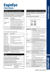
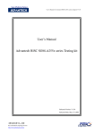
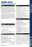
ADAM-4541 Overview Features Fiber optic transmission offers the benefits of wide bandwidth, immunity to EMI/RFI interference, and secure data transmission. The ADAM-4541 can be used as an RS-232/422/485 point-to-point or ring connection for transmitting and converting full/half-duplex signals and their equivalents within a fiber optic environment. Fiber optics are the perfect solution for applications where the transmission medium must be protected from electrical exposure, lightning, atmospheric conditions or chemical corrosion. The ADAM-4541 is specifically designed to link various machinery equipped with RS-232/422/485 communication ports (such as computer systems or manufacturing machines). Using standard ST connectors, the module's fiber optic ports can accommodate a wide range of fiber optic cable sizes, including 62.5/125 µm. Direct plug-and-play Easily mounted on a DIN-rail, panel, or piggybacked Transmission speeds of up to 115.2 kbps Optical fibers enable transmission of up to 2.5 km Half/Full-duplex, bidirectional transmission mode Support for ring-mode Avoid lightning strikes and EMI/RFI Prevents damage from electrostatic discharge Stable and error-free data transmission Automatic internal RS-485 bus supervision No external flow control signals required for RS-485 Transient suppression and over-current protection on RS-232/422/485 data lines LED for power and data flow indication Specifications Packing List Before you begin installing your module, please make sure that the following materials have been shipped: 1 x ADAM-4541 Module with DIN-rail mounting bracket 1 x ADAM-4541 User Manual 1 x Panel Mounting Bracket 1 x Cable for DB-9 to 3-wired (Red:RX, White:TX, Black:GND) If any of these items are missing/damaged, contact your distributor or sales representative immediately. For more information on this and other Advantech products, please visit our websites at: http://www.advantech.com http://www.advantech.com/eAutomation For technical support and service: http://www.advantech.com.tw/eservice This startup manual is for the ADAM-4541 3rd Edition June 2014 1 Startup Manual Fiber Optic : Multimode Wavelength : 820 nm Transmission Distance : 2.5 km Optical Power Budget (attenuation) : 15 dB Casing : ABS with captive mounting hardware Communication Mode : Asynchronous Connector : Plug-in screw terminal Fiber port : ST Transmission Mode : Full/Half-duplex, bidirectional Transmission Rate : Up to 115.2 kbps Power Requirement : Unregulated +10 ~ +30 VDC Operating Temperature : -10 ~ 70°C (14 ~ 158°F) Operating Humidity : 5 ~ 95% (non-condensing) Accessories : DIN-rail mounting adapter, panel mounting bracket Two Year Warranty Notes Part No: 2003454101 Advantech warrants to you, the original purchaser, that this product will be free from defects in materials and workmanship for two years from the date of purchase. This warranty does not apply to any products which have been repaired or altered by persons other than repair personnel authorized by Advantech, or which have been subject to misuse, abuse, accident or improper installation. Advantech assumes no liability under the terms of this warranty as a consequence of such events. If your product is defective, it will be repaired or replaced at no charge during the warranty period. package and ship it prepaid to your dealer. STARTUP MANUAL Fiber Optic to RS-232/422/485 Converter To Set to SW2 Switch and Jumper Settings ADAM-4541 provides three DIP switches that users can configure the settings for their applications. SW1 and SW2 set the data format and baud rate of serial communication. SW3 sets the Transmission mode. SW1 Switch 1 controls the data format. Data can be 9, 10, 11 or 12 bits. The factory default is 10 bits : one start bit, eight data bits, one stop bit and no parity bit. Operation Mode RS-232 RS-422 RS-485 Normal No No Yes Ring Yes Yes Yes SW3 The ADAM-4541 can support ring operation. By setting the DIP2 of SW3, the ADAM-4541 can be set as "Ring" or "Normal" mode. We will introduce more about ring operation in the later chapter. Data Format SW1 1 2 9 bits OFF OFF 10 bits* ON OFF 11 bits OFF ON 12 bits ON ON Reserved SW3 1 Operation Mode SW3 *Default setting When using the converter in combination with other ADAM modules, do not change the default setting of the converter, since ADAM modules have a fixed data format of ten data bits. The option of changing to 9, 11 or 12 bits is for use with other modules (other than ADAM modules) that have different data formats. Should you change the ADAM module’s data format, be aware that you will also have to change the data format on all the other modules in the network. 2 Normal Mode* OFF Ring Mode ON *Default setting SW2 Switch 2 sets the baud rate for RS-485 auto flow control. The options range from 1200 bps to 115.2 kbps. The factory default is 9600 bps. Be aware that when you change the baud rate, you also have to change the baud rate for all of the connected modules accordingly. You can refer to the table below to make sure when you need to set SW2. Baud Rate SW2 1 2 3 4 5 6 7 8 9 1200 bps ON OFF OFF OFF OFF OFF OFF OFF OFF 2400 bps OFF ON OFF OFF OFF OFF OFF OFF OFF 4800 bps OFF OFF ON OFF OFF OFF OFF OFF OFF 9600 bps* OFF OFF OFF ON OFF OFF OFF OFF OFF 19.2 kbps OFF OFF OFF OFF ON OFF OFF OFF OFF 38.4 kbps OFF OFF OFF OFF OFF ON OFF OFF OFF 57.6 kbps OFF OFF OFF OFF OFF OFF ON OFF OFF 115.2 kbps OFF OFF OFF OFF OFF OFF OFF ON OFF RS-232/422 OFF OFF OFF OFF OFF OFF OFF OFF ON *Default setting Note: When using RS-232/422 in ring mode, both position 9 of SW2 and the baud rate need to be configured. And the device MUST be connected to prevent the possibility of communications failure. For example, using RS-232 with a baud rate of 9600 kps in ring mode, both position 4 and position 9 need to be switched ON. But only position 9 needs to be switched on in normal mode. Startup Manual 2 Ring Operation Several ADAM-4541 modules can be cascaded to form a ring connection. With a circumstance that users plan to use a HMI/SCADA to connect multiple kinds of IO device with ADAM-4541, users can apply ring architecture to save lots of cost caused from the number of modules and the length of optical fiber. Following diagrams demonstrates the Ring application. Ring Operation mode is set by DIP2 of SW3. Limitation While applying ring operation, please notice the following limitations. It only supports the half duplex. Up to 50 ADAM-4541 can be connected over a distance of 2.5 km. Under ring operation, RS-232/422/485 all need to set SW2 for baud rate. Normal Operation Startup Manual 3 Ring Operation LED Description On the face plate of module, the LED is a status indicator. The meaning for LED display method is described as following table. Operating Status RS-232/422 RS-485 Status LED Green Red Fiber to Serial ON OFF Serial to Fiber OFF ON Fiber to Fiber ON OFF Idle OFF OFF Fiber to Serial OFF OFF Serial to Fiber ON ON Fiber to Fiber OFF OFF Idle ON OFF Note: The LED display in Ring Mode is the same as in Point-to-Point Mode. Startup Manual 4 Wiring Diagrams Serial Type Pin Assignment RS-232 RX, TX, GND RS-485 (2-wire) DATA+, DATA- (GND) RS-422 (4-wire) TX+, TX-, RX+, RX- (GND) Ring Operation System Startup Manual 5 Troubleshooting Problem Solution The TX and RX connections are reversed. Make sure the fiber connection is made so that the TX of one end is connected to the RX of the other. Poor connection between the ADAM-4541 and the communication port in computer. Make sure the ADAM-4541 is securely plugged into the communication port. Attenuation on the fiber causes the signal level to drop below the accepted level. Reduce attenuation by reducing connector loss, transmission distances, etc. The connection between the communication ports is neither DTE to DTE nor DCE to DCE connection. Add a converter to one of the optical modems, so that the pin assignments from the communication port to the modem are from pin 2 to pin3 and from pin 3 to pin 2. Damage Test If none of the above resolved your problem, your module may be damaged. To test for damage, use the hyper terminal program of MS Windows to perform a loop-back test of the optical modem. This will detect if the module is damaged. Power Supply Front View For the ease of use in industrial environments, the ADAM modules are designed to accept industry standard +24 VDC unregulated power.Operation is guaranteed when using any power supply between +10 and +30 VDC. Power ripples must be limited to 5 V peak to peak, while the voltage in all cases must be maintained between +10 and +30 VDC. All power supply specifications are referenced at the module connector. The power cables should be selected according to the number of modules connected and the length of the power lines. When using a network with long cables, we advise the use of thicker wire, to limit line voltage drop. In addition to serious voltage drops, long voltage lines can also cause interference with communication wires. We advise that the following standard colors (as indicated on the modules) be used for power lines: +Vs (R) Red GND (B) Black Startup Manual 6