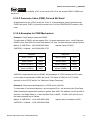
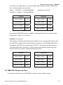
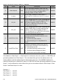
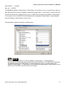
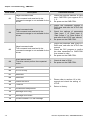
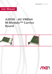
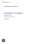
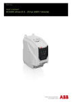
1
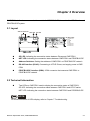
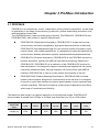
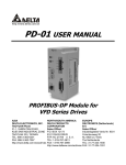
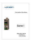
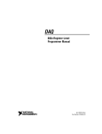
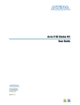
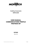
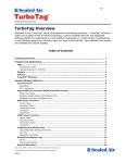
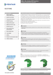
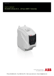
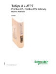
Profibus (CME-PD01)
User Manual
Profibus is a registered trademark of Profibus International.
The information supplied by this document is subject to change without notice. No
responsibility or liability for the correctness of the information supplied within this
document is assumed.
Table of Contents
Chapter 1 Preface ........................................................................................1-1
1.1 Receiving and Inspection....................................................................1-1
1.2 Using this Manual ...............................................................................1-1
Chapter 2 Overview .....................................................................................2-1
2.1 Layout .................................................................................................2-1
2.2 Technical Information .........................................................................2-1
2.3 Functionality........................................................................................2-2
Chapter 3 Profibus Introduction.................................................................3-1
3.1 PROFIBUS .........................................................................................3-1
3.2 PROFIBUS-DP ...................................................................................3-2
Chapter 4 Installation Information..............................................................4-1
4.1 Installation...........................................................................................4-1
4.2 Pin Assignment of PROFIBUS-DP Interface (DB9) ............................4-2
Chapter 5 Communication ..........................................................................5-1
5.1 PROFIBUS Address ...........................................................................5-1
5.2 VFD-E Parameters Settings................................................................5-1
5.3 Cyclical Data of CME-PD01 via PROFIBUS-DP.................................5-2
5.3.1 Useful Data Structure as Defined in PROFIDrive Profile 2.0....... 5-2
5.3.2 Extended Configuration............................................................... 5-3
5.3.3 Default Settings of PZD Structure ............................................... 5-3
5.3.4 Control and Status Words ........................................................... 5-3
5.3.5 Accessing Parameters via PKW Area......................................... 5-5
5.3.5.1 PKE ..................................................................................... 5-5
5.3.5.2 IND ...................................................................................... 5-6
5.3.5.3 Parameter Value (PWE) 3rd and 4th Word ......................... 5-7
5.3.5.4 Examples for PKW Mechanism........................................... 5-7
5.4 CME-PD01 Response Time ............................................................... 5-9
Chapter 6 Parameters Setting in GSD file ................................................. 6-1
6.1 GSD File............................................................................................. 6-1
6.2 Parameters Settings ........................................................................... 6-5
Chapter 7 Troubleshooting......................................................................... 7-1
7.1 LED Displays...................................................................................... 7-1
7.2 Diagnostic Data .................................................................................. 7-2
7.3 Error Codes ........................................................................................ 7-3
Chapter 8 Dimensions................................................................................. 8-1
Chapter 1 Preface
1.1 Receiving and Inspection
All Delta CME-PD01 have gone through rigorous quality control tests at the factory prior to the
shipment. Upon the receive of CME-PD01, please check that the package includes:
1pcs CME-PD01,
1pcs communication cable (for RJ-45, 8 pins),
1 instruction sheet
1.2 Using this Manual
Chapter 2 describes the overview of CME-PD01
Chapter 3 briefly describes the introduction to PROFIBUS and PROFIBUS-DP
Chapter 4 introduces how to install and remove the CME-PD01
Chapter 5 describes the communication with PROFIBUS-DP system
Chapter 6 introduces GSD file and parameter settings in GSD file of CME-PD01
Chapter 7 provides LEDs information, and corrective actions for problem solving
Chapter 8 provides the dimensions of the CME-PD01
Firmware version should conform with VFD-E Drives as table below:
Delta AC Drive
Firmware Version
VFD-E
Version 2.02 and above
Revision September 2007, 2006PDD23000013
1-1
Chapter 1 Preface| CME-PD01
This page intentionally left blank
1-2
Revision September 2007, 2006PDD23000013
Chapter 2 Overview
CME-PD01, defined as a communication module for PROFIBUS-DP, is used to link VFD-E series and
PROFIBUS-DP system.
2.1 Layout
Address Switches NET LED
SP LED
RS-485 (RJ45)
NET SP
ADDH ADDL
CME-P B01
Profibus-DP
Interface (DB9)
1: Reserved
2: EV
3: GND
4: SG5: SG+
6: Reserved
7: Reserved
8: Reserved
SP LED: Indicating the connection status between Drives and CME-PD01
NET LED: Indicating the connection status between CME-PD01 and PROFIBUS-DP
Address Switches: Setting the address of CME-PD01 on PROFIBUS-DP network
RS-485 Interface (RJ-45): Connecting to VFD-E Drives, and supply power to CMEPD01
PROFIBUS-DP Interface (DB9): 9-PIN connector that connects CME-PD01 to
PROFIBUS-DP network
2.2 Technical Information
Two LEDs on CME-PD01 used to display the connection status of CME-PD01:
SP LED: indicating the connection status between CME-PD01 and VFD-E series
NET LED: indicating the connection status between CME-PD01 and PROFIBUS-DP
NOTE
For more information of LEDs display, refer to Chapter 7 Troubleshooting.
Revision September 2007, 2006PDD23000013
2-1
Chapter 2 Overview| CME-PD01
The address in PROFIBUS-DP can be set via two rotary address switches, ADDH
and ADDL, on CME-PD01:
ADDH used as a high 4 bits of address, ADDL used as a low 4 bits of address.
NOTE
For more information of address switches, refer to Chapter 5 Communication.
A specific 8-PIN communication cable for RJ-45, is used to connect the CME-PD01 to
VFD-E series via RS-485 interface. VFD-E series supply the 15V DC power to CMEPD01 through this cable.
PROFIBUS-DP interface (DB9) uses a standard PROFIBUS-DP system interface. We
recommend users use the standard connector to connect CME-PD01 to PROFIBUSDP system. Besides, the CME-PD01 also provides a 4-PIN extended socket for users
to connect it to PROFIBUS-DP system based upon the requirements. However,
please pay attention to the assignment of A1, B1, and A2, B2 on the 4-PIN extended
socket.
CME-PD01 supports baud rates of 9.6kbaud to 12Mbaud.
2.3 Functionality
Cyclical process data exchange (PZD).
Parameter accessing: cyclical accessing of parameters (PKW).
PROFIBUS supports the control commands SYNC and FREEZE for data
synchronization between master and slaves.
Support the configuration of data structure for data exchange with VFD-E series.
2-2
Revision September 2007, 2006PDD23000013
Chapter 3 Profibus Introduction
3.1 PROFIBUS
PROFIBUS is an international, vendor- independent, opening filed bus standard for a wide range
of applications in the fields of manufacturing, production, process and building automation, and
other automation control field.
The PROFIBUS family comprises three types of protocol, PROFIBUS-DP, PROFIBUS-PA and
PROFIBUS-FMS, each of them is used for different tasks:
PROFIBUS-DP (Decentralized Periphery): PROFIBUS-DP is a rapid and low cost
communication connection designed for high-speed data transmission at field level.
PROFIBUS-DP has widespread usage for such items as remote I/O systems, motor
control centers, and variable speed drives. It is designed and optimized especially for
communication between automation systems and decentralized peripheral devices.
PROFIBUS-PA (Process Automation): PROFIBUS-PA is the PROFIBUS solution for
process automation, typically with MBP-IS transmission technology. Based upon
PROFIBUS-DP, PROFIBUS-PA is an extension of the PROFIBUS-DP protocol for
data transmission. It is designed to support intrinsically safe applications and can be
used within hazardous areas, with high explosion risk using intrinsic safe MBP-IS
interface. PROFIBUS-PA is used to connect sensor and controller to the bus.
PROFIBUS-FMS (Fieldbus Message Specification): PROFIBUS-FMS is multiple
master communications designed for communication at the cell level. It is designed
for acyclic or cyclic data transfers at medium speed between control equipment and
cell-level controllers. FMS services open up a wide range of applications and offer a
wide range of functionality and flexibility.
The Maximum cable length in a segment depends on the transmission speed. PROFIBUS-DP
communicates at speeds from 9.6 Kbps to 12 Mbps over distances from 100 to 1,200 meters.
Baud Rate
(bps)
9.6K
19.2K
93.75K
187.5K
500K
1.5M
12M
Length (m)
1200
1200
1200
1000
400
200
100
Revision September 2007, 2006PDD23000013
3-1
Chapter 3 Profibus Introduction| CME-PD01
3.2 PROFIBUS-DP
PROFIBUS-DP is a PROFIBUS communication profile optimized for high-speed, time-critical
data transmission at field level using low-cost connections. PROFIBUS-DP is a suitable
substitute for conventional, costly parallel wiring of 24 V measurement signals in production and
manufacturing automation, as well as for analog 4(0) to 20mA measurement signals in process
automation.
3-2
Revision September 2007, 2006PDD23000013
Chapter 4 Installation Information
Please make sure that the power of VFD-E series is OFF before installation or remove the CMEPD01 from network.
4.1 Installation
Improper installation of the CME-PD01 will cost its life usage. Please follow the instructions to
install your CME-PD01 carefully.
STEP 1
STEP 2
STEP 3
STEP 4
Revision September 2007, 2006PDD23000013
4-1
Chapter 4 Installation Information| CME-PD01
Power Supply
The power of CME-PD01 is supplied from VFD-E series Drive. The VFD-E firmware
version should be V2.02 and above. No external power needed. The +15VDC power is
applied to CME-PD01 directly via a specific 6-PIN communication cable (This 6-PIN
cable is packed together with CME-PD01).
CME-PD01 is energized while the power is applied to the VFD-E series, then the SP
LED will be steady green.
4.2 Pin Assignment of PROFIBUS-DP Interface (DB9)
Use PROFIBUS-DP interface (DB9) of CME-PD01 connecting CME-PD01 to PROFIBUS DP
system. The terminals are short-circuit-proof and isolated.
1
5
6
4-2
9
Pin
Designation
Description
1
-
Not assigned
2
-
Not assigned
3
Rxd/TxD-P
Receive/send data P (B)
4
-
Not assigned
Data reference potential (C)
5
DGND
6
VP
Supply voltage positive
7
-
Not assigned
8
RxD/TxD-N
Receive/send data N (A)
9
-
Not assigned
Revision September 2007, 2006PDD23000013
Chapter 5 Communication
Please make sure that you have read chapter 4 and fully understood the CME-PD01 installation.
5.1 PROFIBUS Address
CME-PD01 has two rotary switches to set the PROFIBUS address, the only way for user to set
the address. The address switches, ADDH and ADDL, allow user to set the address in a HEX
format. ADDH is used to set high 4 bits of address, and ADDL is used to set low 4 bits of address.
If both ADDH and ADDL are set to F, and CME-PD01 is power ON or re-power ON, then CMEPD01 will enter the TEST mode, the SP LED and NET LED will be in steady orange.
Address
1..0x7D
0 or 0x7E..0xFE
0xFF
Description
Valid PROFIBUS address
Invalid PROFIBUS address
Enter TEST mode
NOTE
Setting changes via address switches will not effective when CME-PD01 is operating. This
means the setting changes will effective after CME-PD01 power re-boot. Please understand this
cold restart must be initiated by toggling the power to OFF and then ON.
5.2 VFD-E Parameters Settings
CME-PD01 is designed to communicate with VFD-E series via MODBUS communication port.
Prior to the connection, users have to set parameters below in the VFD-E series:
Set the communication protocol of VFD-E series to RTU 8, N, 2.
Set the baud rate of VFD-E series to 9600bps.
Set the frequency source for VFD-E series to operate via RS485.
Set the operation source of VFD-E series via MODBUS communication.
Refer to the following table for the above settings when connecting to VFD-E series:
Revision September 2007, 2006PDD23000013
5-1
Chapter 5 Communication| CME-PD01
VFD-E type
Baud Rate 9600
P09.01=1
RTU 8, N, 2
P09.04=3
Freq. Source
P02.00=3
Command Source
P02.01=3
After these settings completed, connecting CME-PD01 and VFD-E series via communication
cable mentioned earlier, CME-PD01 is then energized. Two LEDs will be firstly in orange
because CME-PD01 is initialized and test itself. SP LED will be then in steady green since that
the connection is established between CME-PD01 and VFD-E series.
5.3 Cyclical Data of CME-PD01 via PROFIBUS-DP
CME-PD01 is controlled via cyclical PROFIBUS-DP channel. This channel can be used to
access the parameters of VFD-E series.
5.3.1 Useful Data Structure as Defined in PROFIDrive Profile 2.0
The structure of useful data for the cyclical channel is defined in the PROFIDrive Profile,
version 2.0. Please refer to the Parameter Process data Object (PPO).
PKW
PKE
IND
1st
word
2nd
word
PZD1
PWE
STW
ZSW
3rd
4th
1st
word word word
PZD
PZD2
HSW PZD3 PZD4 PZD5 PZD6 PZD7 PZD8 PZD9
HIW
2nd
3rd
4th
5th
6th
7th
8th
9th
word word word word word word word word
PZD
10
10th
word
PPO1
PPO2
PPO3
PPO4
PPO5
PKW: Parameter ID/value
STW: Control word
PZD: Process data
ZSW: Status word
PKE: Parameter ID
HSW: Main setpoint
IND: Sub-index
HIW: Main actual value
PWE: Parameter value
5-2
Revision September 2007, 2006PDD23000013
Chapter 5 Communication| CME-PD01
NOTE
CME-PD01 supports PPO1 and PPO3 structure only.
5.3.2 Extended Configuration
In addition to the PPO types, cyclical data can also be configured to EXT CONF 1 or EXT
CONF 2 (see table below). These two extended configuration both have four process
data words. The areas of consistency can be set flexibly.
PKW
PKE
IND
1st
word
2nd
word
PZD
PZD1 PZD2
PWE
STW HSW PZD3 PZD4 PZD5 PZD6 PZD7 PZD8 PZD9
ZSW
HIW
3rd
4th
1st
2nd
3rd
4th
5th
6th
7th
8th
9th
word word word word word word word word word word word
EXT CONF 1
EXT CONF 2
PZD
10
10th
word
5.3.3 Default Settings of PZD Structure
CME-PD01 must receive the user parameters from master that configured via GSD file.
The default settings of PZD structure are as follows:
STW1: Control Word, mapping to MODBUS address 0x2000 of VFD-E series.
HSW: Main set point, mapping to MODBUS address 0x2001 of VFD-E series.
ZSW: Drives status, mapping to MODBUS address 0x2101 of VFD-E series.
HIW: Main command frequency, mapping to MODBUS address 0x2102 of VFD-E series.
DP master -> VFD-E series:
PZD3: No default assignment
PZD4: No default assignment
VFD-E series-> DP master:
PZD3: Output frequency, mapping to MODBUS address 0x2103 of VFD-E series.
PZD4: Output current, mapping to MODBUS address 0x2104 of VFD-E series.
5.3.4 Control and Status Words
CME-PD01 supports the PPO1 and PPO3 data structure. However, it does not support
the bit assignments of control and status words in PROFIDRV. It only supports the
DELTA VFD-E series control and status words.
Control word (data from DP to VFD-E series)
00B: No function
01B: Stop
Bit 0~1
10B:Run
11B:JOG + Run
Bit 2~3
Reserved
Bit 4~5
00B:No function
01B:FWD
10B:REV
Revision September 2007, 2006PDD23000013
5-3
Chapter 5 Communication| CME-PD01
11B:Change direction
00B:1st Accel / Decel time
Bit 6~7
01B:2nd Accel / Decel time
Bit 8~15 Reserved
Frequency Command
Bit 0
1:E.F. ON
Bit 1
1:Reset command
Bit 2~15 Reserved
NOTE
Table above is for reference only, please check VFD-E series user manual for details. The
control word that is mapping to the address of VFD-E series can be carried out by CME-PD01,
so the bit assignments in the user manual of VFD-E series is valid.
Status word (data from VFD-E series to DP)
LED status
Bit 0~1
00B: RUN LED light on, STOP LED light off (Drive Stop)
01B: RUN LED blink, STOP LED light up (Drive decelerate to stop)
10B: RUN LED light up, STOP LED blink (Drive standby)
11B: RUN LED light on, STOP LED light off (Drive Run)
Bit 2
1: JOG is active
00B: REV LED light off, FWD LED light up (Forward)
Bit 3~4
01B: REV LED blink, FWD LED light up (Reverse to Forward)
10B: REV LED light up, FWD LED blink (Forward to Reverse)
11B: REV LED light up, FWD LED light off (Reverse)
Bit 5~7
Bit 8
1: Master frequency controlled by communication
Bit 9
1: Master frequency controlled by external terminal (EXT)
Bit 10
1: Operation command controlled by communication interface
Bit 11~15
5-4
Reserved
Reserved
Revision September 2007, 2006PDD23000013
Chapter 5 Communication| CME-PD01
NOTE
Table above is for reference only, please check VFD-E series user manual for details.
CME-PD01 will get the status word from VFD-E series, so the bit assignments in the user
manual of VFD-E series is valid.
5.3.5 Accessing Parameters via PKW Area
In cyclical data, CME-PD01 can provide request and response (read / write) message to
access the VFD-E parameters. Due to the request and response mechanism, the master
must send the request until receives a corresponding response.
Following 4 words are for PKW area:
Word 1
Parameter ID (PKE)
15
12
11
SPM
AK
Word 2
10
Parameter number (PNU)
Parameter sub-index (IND)
15
8
Word 3
PWE1
Reserved
Word 4
PWE2
Read/Write parameters
7
5.3.5.1 PKE
Bits 0 to 10 (PNU) contain the number of the relevant parameter.
Bit 11 is reserved.
Bits 12 to 15 (AK) contain the request or the response identifier.
Request identifier (master
CME-PD01)
Request Identifier
Description
0
No request
1
Request parameter
value
2
Modify parameter value
(word)
Response identifier (CME-PD01
master)
Request Identifier
Description
0
No response
1
Send parameter value
(word)
7
Cannot process request
(with error number)
Revision September 2007, 2006PDD23000013
5-5
Chapter 5 Communication| CME-PD01
Fault numbers for "Cannot process request" response
NO.
Description
0
Illegal Parameter number
Parameter does not exist
1
Parameter value cannot be
modified
Parameter is a read-only
parameter or can not change
in current state
2
Minimum/maximum not
reached / exceeded
18
Other error
5.3.5.2 IND
Structure of IND for cyclical communication via PPOs
PKE
HIGH
15
IND
LOW
HIGH
14
PWE1
LOW
13
12
11-8
Para Page selection
0
3
2
HIGH
PWE2
LOW
7
HIGH
LOW
0
Not Used
1
2 2 2 2
0
Function of Parameter Page Selection
Basic PNU
5-6
Total PNU
(B.PNU bit 10-0 of PKE)
Page selection
(P.PNU)
(B.PNU+P.PNU*2000)
0…1999
0
0…1999
0…1999
1
2000…3999
0…1999
2
4000…4999
…
…
…
0…1999
15
30000…31999
Revision September 2007, 2006PDD23000013
Chapter 5 Communication| CME-PD01
NOTE
In IND, Bit 15 uses a multiplier of 20, so the value of Bit 15 for the access P2000- P3999 must
be set to 1.
5.3.5.3 Parameter Value (PWE) 3rd and 4th Word
All parameters for the VFD-E series are 16-bit. A 16-bit parameter value is transferred by
PWE2 (4th word). PWE1 (3rd word) must be set to 0 on the PROFIBUS-DP master in this
case.
5.3.5.4 Examples for PKW Mechanism
Example 1: Read data of parameter P0003
To read value of P0003, set the request ID to 1 (request parameter value - word). Because
P0003 is less than 2000, the Para Page Select is 0, thus, the data sequence are as follows:
Master
CME-PD01 : 1003 0000 0000 0000
CME-PD01
request value of P0003
Master : 1003 0000 0000 1770
Request
Response
Word 1 (PKE)
1003
Word 1 (PKE)
1003
Word 2 (IND)
0000
Word 2 (IND)
0000
Word 3 (PWE1)
0000
Word 3 (PWE1)
0000
Word 4 (PWE2)
0000
Word 4 (PWE2)
1770
CME-PD01 responds the value of P0003. All parameters in VFD-E series are 16-bit value,
so the value is transferred to PWE2 (4th word). The value of P0003 is 0x1770 (6000
decimal). In the VFD-E series, it is “Maximum Output Frequency”.
Example 2: Read command frequency in VFD-E series (0x2102)
To read value of command frequency, set the request ID to1, we should set the Para Page
Select because the parameter address is greater than 2000. The address 0x2102 is 8450 in
decimal, if set Page Select to 4, then the Basic PNU is 8450 – 4*2000 = 450 (0x1c2), thus,
the data sequence are as follows:
Master
CME-PD01 : 11C2 2000 0000 0000
CME-PD01
request value of address 0x2102
Master : 11C2 2000 0000 0868
Revision September 2007, 2006PDD23000013
5-7
Chapter 5 Communication| CME-PD01
Request
Word 1 (PKE)
Response
11C2
Word 1 (PKE)
11C2
Word 2 (IND)
2000
Word 2 (IND)
2000
Word 3 (PWE1)
0000
Word 3 (PWE1)
0000
Word 4 (PWE2)
0000
Word 4 (PWE2)
0868
Example 3: Write data 2 to parameter P0804
To write data to P0804, request ID is set to 2 (Modify parameter value - word), Para Page
Select should be set because the parameter address is greater than 2000. The address of
P0804 is 0x0804, which is 2052 in decimal, if set Page Select to 1 (bit 15 of IND is 1), then
the Basic PNU is 2052 – 1*2000 = 052 (0x34), thus, the data sequence are as follows:
Master
CME-PD01: 2034800000000002
CME-PD01
write data to P0804
Master: 1034800000000002
Request
Response
Word 1 (PKE)
2034
Word 1 (PKE)
1034
Word 2 (IND)
8000
Word 2 (IND)
8000
Word 3 (PWE1)
0000
Word 3 (PWE1)
0000
Word 4 (PWE2)
0002
Word 4 (PWE2)
0002
All parameters values in VFD-E series are 16-bit, so the data may be transferred to PWE2
(4th word).
NOTE
VFD-E series will write the data to EEPROM. When using PKW to change the value of
parameter, the data will be written to EEPROM directly. However, the frequent writing action
may result in EEPROM damage and the EEPROM will have no capability of directly
saving data. So please pay close attention on it.
Example 4: Read diagnostic data
User can use the special address to read the current diagnostic data. Please refer to Section
6.2 for details. The diagnostic address starts from 0x7500 to 0x7504 (5 words). To read
diagnostic data in these addresses, request ID is set to 1, Para Page Select should be set
because the parameter address is greater than 2000. The address 0x7500, which is 29952
5-8
Revision September 2007, 2006PDD23000013
Chapter 5 Communication| CME-PD01
in decimal, if set Page Select to 14, then the Basic PNU is 29952-14*2000=1952(0x7A0),
thus, the data sequence are as follows:
Master - > CME-PD01 : 17A0700000000000
read data from 0x7500
CME-PD01 - > Master : 17A0700000000300
Request
Response
Word 1 (PKE)
17A0
Word 1 (PKE)
17A0
Word 2 (IND)
7000
Word 2 (IND)
7000
Word 3 (PWE1)
0000
Word 3 (PWE1)
0000
Word 4 (PWE2)
0000
Word 4 (PWE2)
0300
If the data that CME-PD01 returns is 0x0300, it indicates that Scan port is disconnected.
Please refer to Section 7.2 for details.
Example 5: Access error
When failing to read/write parameters by using PKW, an error message will be shown from
the CME-PD01. Suppose that the data sequence master sent is 202D 8000 0000 0002. If
this address (0x07FD) cannot be found by the VFD-E, it will respond the data sequence
702D 8000 0000 0000, request ID is 7 which means cannot process request (with error
number), and error number is 0 (Illegal Parameter Number).
Request
Response
Word 1 (PKE)
202D
Word 1 (PKE)
702D
Word 2 (IND)
8000
Word 2 (IND)
8000
Word 3 (PWE1)
0000
Word 3 (PWE1)
0000
Word 4 (PWE2)
0002
Word 4 (PWE2)
0000
5.4 CME-PD01 Response Time
The response (refresh) time via PROFIBUS connection can be divided in 3 parts:
Revision September 2007, 2006PDD23000013
5-9
Chapter 5 Communication| CME-PD01
T1: transmission time between Master and CME-PD01
T2: waiting time for CME-PD01 buffer
T3: transmission time between CME-PD01 and VFD-E
T1
Master
CME-PD01 Timer
Data Buffer
T3
VFD
series
Drives
T2
T1 depends on the actual transmission speed and the type of master in use.
T2 depends on the internal timer of CME-PD01. Data is transmitted to VFD-E series per 70ms
triggered by a timer. User cannot change the time-out interval.
T3 depends on the Modbus communication between CME-PD01 and VFD-E series.
So the response (refresh) time is,
Max. response (refresh) time = T1 + T2 (70ms) + T3
In fact, the actual response (refresh) time is less than the Max. response (refresh) time. When
the data is send to CME-PD01, CME-PD01 will save the data to data buffer. If the timer is in
time-out, the data will be transmitted to VFD-E immediately.
5-10
Revision September 2007, 2006PDD23000013
Chapter 6 Parameters Setting in GSD file
6.1 GSD File
A GSD file is a text file used to identify PROFIBUS-DP device (Master or Slave), which contains the
necessary data for the configuration of DP slaves within a standard DP master. Typical information in
a GSD file are Vendor information, supported Baud rates, Timing information, supported
Options/features and Available I/O signals. The GSD file is the fundamental building block for the
master parameter record. Please download the GSD file at Delta website
http://www.delta.com.tw/product/em/drive/ac_motor/download/optional/PD_2p00.GSD
GSD-File for Delta VFD series Drives
File: DELT08DB.GSD
File start: ===========================================================
#Profibus_DP
; Unit-Definition-List:
GSD_Revision
=1
Vendor_Name
= "Delta Electronics"
Model_Name
= "VFD DRIVES"
Revision
Ident_Number
= "Rev. 1"
= 0x08DB
Protocol_Ident
=0
Station_Type
FMS_supp
=0
=0
Hardware_Release
= "V1.0"
Software_Release
= "V1.0"
Redundancy
=0
Repeater_Ctrl_Sig
24V_Pins
=2
=0
Implementation_Type = "SPC3"
Bitmap_Device
= "VFDDRV"
Bitmap_Diag
= "VFDDRV"
Bitmap_SF
= "VFDDRV"
Slave_Family
= 1@TdF@Delta VFD Drives
Revision September 2007, 2006PDD23000013
6-1
Chapter 6 Parameters Setting in GSD file| CME-PD01
Auto_Baud_supp
=1
9.6_supp
=1
19.2_supp
=1
93.75_supp
=1
187.5_supp
=1
500_supp
=1
1.5M_supp
=1
3M_supp
=1
6M_supp
=1
12M_supp
=1
MaxTsdr_9.6
= 60
MaxTsdr_19.2
= 60
MaxTsdr_93.75
= 60
MaxTsdr_187.5
= 60
MaxTsdr_500
= 100
MaxTsdr_1.5M
= 150
MaxTsdr_3M
= 250
MaxTsdr_6M
= 450
MaxTsdr_12M
= 800
Freeze_Mode_supp
=1
Sync_Mode_supp
=1
Set_Slave_Add_supp = 0
Min_Slave_Intervall
=1
Modular_Station
Max_Module
=1
=1
Max_Input_Len
= 32
Max_Output_Len
= 32
Max_Data_Len
= 64
Modul_Offset
=0
Fail_Safe
=0
Max_Diag_Data_Len = 16
ORDERNUMBER
= "PD-01"
Max_User_Prm_Data_Len
= 26
User_Prm_Data_Len
= 26
User_Prm_Data
= 0x20,0x00,\
0x20,0x01,\
0x00,0x00,\
6-2
Revision September 2007, 2006PDD23000013
Chapter 6 Parameters Setting in GSD file| CME-PD01
0x00,0x00,\
0x21,0x01,\
0x21,0x02,\
0x21,0x03,\
0x21,0x04,\
0x00,0x01,\
0x00,0x02,\
0x00,0x02,\
0x00,0x01,\
0x00,0x00
Module = "4 PKW, 2 PZD (PPO 1)
" 0xF3, 0xF1
EndModule
Module = "0 PKW, 2 PZD (PPO 3)
" 0x00, 0xF1
EndModule
Module = "4 PKW, 4 PZD
" 0xF3, 0xF3
EndModule
Module = "0 PKW, 4 PZD
" 0x00, 0xF3
EndModule
PrmText = 1
Text(0) = "Address discontinuous"
Text(1) = "Address continue"
EndPrmText
PrmText = 2
Text(0) = "Ignore and Continue"
Text(1) = "Stop accord to Pr.STOP METHOD"
EndPrmText
PrmText = 3
Text(0) = "Stop DataExchange & Report Fault"
Text(1) = "Continue & Report Alarm"
Text(2) = "Ignore & Continue DataExchange"
EndPrmText
ExtUserPrmData = 1 "Data Input 1(PD-01 -> VFD)"
Unsigned16 0x2000 0-65535
EndExtUserPrmData
ExtUserPrmData = 2 "Data Input 2"
Unsigned16 0x2001 0-65535
EndExtUserPrmData
ExtUserPrmData = 3 "Data Input 3"
Revision September 2007, 2006PDD23000013
6-3
Chapter 6 Parameters Setting in GSD file| CME-PD01
Unsigned16 0x0000 0-65535
EndExtUserPrmData
ExtUserPrmData = 4 "Data Input 4"
Unsigned16 0x0000 0-65535
EndExtUserPrmData
ExtUserPrmData = 5 "Data Output 1(VFD -> PD-01)"
Unsigned16 0x2101 0-65535
EndExtUserPrmData
ExtUserPrmData = 6 "Data Output 2"
Unsigned16 0x2102 0-65535
EndExtUserPrmData
ExtUserPrmData = 7 "Data Output 3"
Unsigned16 0x2103 0-65535
EndExtUserPrmData
ExtUserPrmData = 8 "Data Output 4"
Unsigned16 0x2104 0-65535
EndExtUserPrmData
ExtUserPrmData = 9 "d_state"
Unsigned16 1 0-1
Prm_Text_Ref = 1
EndExtUserPrmData
ExtUserPrmData = 10 "din_len"
Unsigned16 2 0-4
EndExtUserPrmData
ExtUserPrmData = 11 "dout_len"
Unsigned16 2 0-4
EndExtUserPrmData
ExtUserPrmData = 12 "LossDPComTreat"
Unsigned16 1 0-1
Prm_Text_Ref = 2
EndExtUserPrmData
ExtUserPrmData = 13 "LossSPComTreat"
Unsigned16 0 0-2
Prm_Text_Ref = 3
EndExtUserPrmData
Ext_User_Prm_Data_Ref(0) = 1
Ext_User_Prm_Data_Ref(2) = 2
Ext_User_Prm_Data_Ref(4) = 3
Ext_User_Prm_Data_Ref(6) = 4
Ext_User_Prm_Data_Ref(8) = 5
6-4
Revision September 2007, 2006PDD23000013
Chapter 6 Parameters Setting in GSD file| CME-PD01
Ext_User_Prm_Data_Ref(10) = 6
Ext_User_Prm_Data_Ref(12) = 7
Ext_User_Prm_Data_Ref(14) = 8
Ext_User_Prm_Data_Ref(16) = 9
Ext_User_Prm_Data_Ref(18) = 10
Ext_User_Prm_Data_Ref(20) = 11
Ext_User_Prm_Data_Ref(22) = 12
Ext_User_Prm_Data_Ref(24) = 13
File END: ==========================================================
NOTE
The required GSD file is available and can be downloaded from the DELTA web site
http://www.delta.com.tw, or you can copy this text to a text editor such as NOTEPAD, and save
it as a GSD file named “DELT08DB.GSD”. Please make sure the extension file name is “.GSD”,
NOT “.GSD.TXT”.
6.2 Parameters Settings
The parameters in GSD file are used for the configuration of the PROFIBUS network. The
parameters description are shown in the following table:
Item
Name
Type
Description
This is a MODBUS address. The 1st word of
cyclic output data PZD will be sent to this
address.
This is a MODBUS address. The 2nd word of
cyclic output data PZD will be sent to this
address.
Default
1
Data Input 1
UINT
2
Data Input 2
UINT
3
Data Input 3
UINT
This is a MODBUS address. The 3rd word of
cyclic output data PZD will be sent to this
address if selecting module "4 PKW, 4 PZD".
0x0000
4
Data Input 4
UINT
This is a MODBUS address. The 4th word of
cyclic output data PZD will be sent to this
address if selecting module "4 PKW, 4 PZD".
0x0000
5
Data Output 1
UINT
This is a MODBUS address. CME-PD01 will
monitor this address, and copy the return data
to the 1st word of cyclic input data PZD.
0x2101
6
Data Output 2
UINT
This is a MODBUS address. CME-PD01 will
monitor this address, and copy the return data
to the 2nd word of cyclic input data PZD.
0x2102
7
Data Output 3
UINT
This is a MODBUS address. CME-PD01 will
monitor this address, and copy the return data
to the 3rd word of cyclic input data PZD if
selecting module "4 PKW, 4 PZD".
0x2103
Revision September 2007, 2006PDD23000013
0x2000
0x2001
6-5
Chapter 6 Parameters Setting in GSD file| CME-PD01
Item
Name
Type
Description
Default
8
Data Output 4
UINT
This is a MODBUS address. CME-PD01 will
monitor this address, and copy the return data
to the 4th word of cyclic input data PZD if
selecting module "4 PKW, 4 PZD".
9
d_state
UINT
This is a flag. If address in Data Output 1 ~
Data Output 4 is continuous, set it to 1 or set it
to 0.
0x0001
UINT
This is a length, and unit is word. It specifies the
length of CME-PD01 to process data in PZD. If
user selects module "4 PKW, 4 PZD", but
din_len is 3, CME-PD01 will process 3 word
and ignore the 4th word.
0x0002
UINT
This is a length, and unit is word. It specifies the
length of CME-PD01 to monitor data from the
AC Drive. If user selects module "4 PKW, 4
PZD", but dout_len is 3, CME-PD01 will monitor
3 word and ignore the 4th word.
0x0002
10
din_len
11
dout_len
0x2104
It is used to decide the method when
communication with Profibus network is lost.
The settings can be:
12
LossDPComTreat
UINT
00 – Ignore event and continue;
0x0001
01 – Stop according to Pr “Stop Method” in
VFD-E.
It is used to decide the method when the SP
communication (SCANport communication) is
lost. The settings can be:
13
LossSPComTreat
UINT
00 – Stop data exchange and have fault;
0x0000
01 – Continue data exchange and alarm;
02 – Ignore and continue data exchange.
If the address in Data Output 1 ~ Data Output 4 is continuous, then set d_state to 1, CME-PD01 will
get starting address from Data Output 1. The next data will be got from the address next to the
starting address, and the reading length is determined by dout_len. If the MODBUS address for
reading is discontinuous, please set d_state to 0, CME-PD01 will also get starting address from Data
Output 1, but the difference is other data will be got from the address saved in Data Output 2, Data
Output 3 and Data Output 4 in order.
Example, if
Data Output 1
= 0x2100;
Data Output 2
= 0x2101;
Data Output 3
= 0x2102;
6-6
Revision September 2007, 2006PDD23000013
Chapter 6 Parameters Setting in GSD file| CME-PD01
Data Output 4
= 0x2103;
dout_len = 0x0003;
The MODBUS address in Data Output 1~Data Output 4 is continuous, so you can set the d_state to 1,
then CME-PD01 will monitor the address starting from Data Output 1, and monitor 3 words from VFDE series Drives one time. When the dout_len is 3, CME-PD01 will ignore the address in Data Output
4. If d_state is set to 0, CME-PD01 will read data from the address in Data Output 1, and read data
from the address in Data Output 2, and so forth.
The parameters settings are shown in the following:
NOTE
Please do not set d_state to 1 when the address in Data Output 1 ~ Data Output 4 is
discontinuous to avoid parameter process error and IO disconnect. The CME-PD01 just checks
the address starting from Data Output 1 to Data Output [dout_len-1], in other words, if the
address in Data Output 1 ~ Data Output 3 is continuous, but the address in Data Output 4 is not,
and dout_len is 0x0003, then the check still can pass.
Revision September 2007, 2006PDD23000013
6-7
Chapter 6 Parameters Setting in GSD file| CME-PD01
This page intentionally left blank
6-8
Revision September 2007, 2006PDD23000013
Chapter 7 Troubleshooting
7.1 LED Displays
Two LEDs, SP and NET LED, are used to monitor the CME-PD01 communication status.
NET LED
State
LED is off
Indication
No power
Corrective Actions
1.
Verify that the power supply of CME-PD01.
2.
Check whether the power supply is
connected and that power is applied to the
CME-PD01 through the connector.
Check whether the switch value is valid, valid
Rapid Flashing Invalid PROFIBUS address
value of slave is within 1-125. Set the valid value
Red LED
set via switch
and re-power
1. Communication link to
PROFIBUS, but No
Flashing Red
LED
cyclical data exchanged
2. Extended user
Parameters are sent by master (from GSD file).
For example, if d_state is set to 1, ensure the data
in Data Output 1 ~ Data Output [ dout_len-1] are
continuous addresses. Otherwise, CME-PD01 will
not be able to pass the Parameterization check.
parameter error
Red LED
No connection to
PROFIBUS
Flashing
Green LED
“Master” is in “Stop” mode,
cyclical process data
exchange is in progress,
but setting is invalid
(control word = 0)
Green LED
Cyclic data is exchanging
and working
Revision September 2007, 2006PDD23000013
1.
Verify that network installation is OK.
2.
Verify that PLC is working.
3.
Verify that switch address setting is correct.
Set PLC to RUN mode, and send the control
command to CME-PD01.
7-1
Chapter 7 Troubleshooting| CME-PD01
SP LED
State
Indication
LED is off
Flashing Red
LED
Corrective Actions
1.
Verify that the power supply of CME-PD01
No power
2.
Check whether the power supply is
connected and that power is applied to the
CME-PD01 through the connector
CRC check error
Check if the communication setting in VFD-E is
(9600, <8,N,2>, RTU)
Connection failure, or no
connection
Red LED
Flashing
Green LED
AC Drive returns error
code
Green LED
Operating normally
1.
Check whether the connection between the
VFD-E and RS485 of CME-PD01 is correct
2.
Re-connect and ensure that the wire
specification is correct
1.
Check the AC Drive type and version.
2.
Check the PLC program, and ensure the
communication address in CME-PD01 is
correct.
NOTE
If both SP LED and NET LED are in steady orange, it indicates that CME-PD01 is in “test mode”.
Please do not set the communication address of CME-PD01 to 0XFF at this time. Be sure to set
it to other value and re-power on the CME-PD01.
7.2 Diagnostic Data
CME-PD01 provides 16 bytes diagnostic data when the abnormal communication occurs or
parameter “LossSPComTreat” is set to “Continue data exchange and report alarm”. It includes 6
bytes standard diagnostic data and 10 bytes device related diagnostic data. The following table
shows the meanings of the 16 bytes:
Bytes 1-6
Byte 7
Byte 8
Byte 9
Bytes 10-16
Standard
diagnostic data
Length in bytes
SP
communication
status
Error code
Reserved
Byte 7 indicates the length of device related diagnostic data, including itself. So if byte 7 is 10 (0Ahex),
it indicates it has 10 bytes (including byte 7) for the device related diagnostic data.
Byte 8 indicates the SP communication status when the error occurs, and the valid value should be
shown as follows:
7-2
Revision September 2007, 2006PDD23000013
Chapter 7 Troubleshooting| CME-PD01
00 – Normal
01 – CRC check error
02 – VFD-E returns error code
03 – Communication is time-out
Byte 9 indicates the error code when byte 8 is 02 (VFD-E will return error code). Refer to the Section
7.3 for the meanings of invalid code.
User can get the diagnostic data via PZD area any time. Following table is some special MODBUS
Description
Comm.
address
addresses that CME-PD01 provides to indicate the diagnostic status.
0x7500
High
byte
Low
byte
SP
Comm.
status
Error
code
0x7501
High
byte
Low
byte
0x7502
High
byte
Low
byte
0x7503
High
byte
Low
byte
0x7504
High
byte
Low
byte
Reserved (factory setting is 0)
User can get these data through “Data Output 1”, or “Data Output 2”, or “Data Output 3”, or “Data
Output 4” in parameters. For example, if “Data Output 1” is set to 0x7500, that means the diagnostic
data can be got from address 0x7500, and the return data from the 1st word of address 0x7500 in
PZD area is the dialogic data.
NOTE
These special addresses are read-only, it will fail if user tries to write data.
7.3 Error Codes
If there is a communication error detected between CME-PD01 and VFD-E series Drives, the error
code will be displayed on the digital keypad of VFD-E.
VFD-E can process the message from CME-PD01 if the communication setting is valid. But if the
command of message is invalid, the VFD-E will respond a report message that has error codes listed
in table below, to CME-PD01.
Revision September 2007, 2006PDD23000013
7-3
Chapter 7 Troubleshooting| CME-PD01
Error Code
Description
Illegal command code
01
Corrective Actions
1.
The command code received in the
command message is not available for the
drives.
2.
03
Check the Parameter number in
PKW area, and refer the VFD-E user
manual.
2.
The command code received in the
command message is not available for the
drives.
Check the settings of parameters
“Data Input 1” to “Data Input 4”,
“Data Output 1” to “Data Output 4”,
and refer to the VFD-E user manual.
3.
Re-power on the CME-PD01.
1.
Illegal command code
Check the parameter data (PWE2) in
PKW area, and refer the VFD-E user
manual.
The command code received in the
2.
command message is not available for the
drives.
Check the PLC program to confirm
the data transmitted to CME-PD01
from master is valid.
3.
Slave device failure
7-4
Re-power on the CME-PD01.
1.
Illegal command code
02
Check the Request Identifier in PKW
area. CME-PD01 just supports ID 0,
1, 2.
04
The drive cannot perform the requested
action.
05
Reserved
06
VFD-E is busy
07
Reserved
08
Reserved
09
Check sum error
10
Time-out
11
Invalid baud rate/protocol
12
Message is too long
13
Message is too short
14
Invalid character is in the message
Re-power on the CME-PD01.
1.
Check all data in PKW.
2.
Re-power on the CME-PD01.
1.
Please refer to section 4.2 in this
manual and check the setting of
VFD-E.
2.
Return to factory.
Revision September 2007, 2006PDD23000013
Chapter 8 Dimensions
NET SP
ADDH ADDL
CME-P B01
57.3 [2.26]
59.7 [2.35]
3.6 [0.14]
72.2 [2.84]
34.8 [1.37]
Revision September 2007, 2006PDD23000013
3.5 [0.14]
8-1