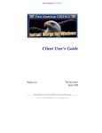
1
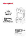
User Instructions
Model 404
Intrinsically Safe
Vibrating Wire Readout
S-404-03 rev 0
17-10-13
Contents
1
Introduction ................................................................................................................................ 3
2
Intrinsically Safe Parameters ..................................................................................................... 4
3
Principle of Operation ................................................................................................................ 5
4
Front Panel and Connections ..................................................................................................... 6
5
User Operation ........................................................................................................................... 7
5.1
POS (POSITION) BUTTON ....................................................................................................... 7
5.2
MODE BUTTON ....................................................................................................................... 8
5.3
CFG (CONFIGURATION) BUTTON ........................................................................................... 8
6
Low Battery Indication and Auto-Off ...................................................................................... 10
7
Maintenance............................................................................................................................. 11
8
Calibration ................................................................................................................................ 12
9
Troubleshooting ....................................................................................................................... 12
10
Specifications ............................................................................................................................ 13
11
Accessories ............................................................................................................................... 14
12
Connector Pin Outs .................................................................................................................. 14
Page 2 of 14
1
Introduction
The Model 404 Vibrating Wire (VW) Readout is designed to monitor and read vibrating wire type
sensors, such as piezometers, uniaxial and biaxial stressmeters.
Based on the Geokon GK-404 VW readout, the Model 404 has been approved as intrinsically safe for
use in underground coal mines to IECEx.ia. It is housed in a rugged, splash proof, stainless steel case
and comes with a protective cover.
Designed as a hand held unit, the tactile membrane keypad allows single handed use, while the
large, backlit display allows easy reading in underground situations. The battery source is inbuilt, and
rechargeable, and the unit comes complete with a wall charger for use outside of hazardous areas.
Operation is the same as for the Geokon GK-404, and allows reading of vibrating wire sensors over a
range of frequency sweeps and units, including digits (Hz2x10-3), period (µs) and frequency (Hz).
The Model 404 is designed for use with specifically designated sensors available from Geokon Inc.
The Intrinsic Safety certification is for the readout in combination with those sensors. It cannot be
used in hazardous environments with any other sensors, regardless of their characteristics.
If the readout, wiring and sensor are all located in a safe environment the Model 404 can be used to
monitor any vibrating wire sensor that will respond to one of the six excitation states, listed on page
8.
Page 3 of 14
2
Intrinsically Safe Parameters
Approval for use in underground coal mines has been given by Simtars, by way of certification IECEx
SIM 13.0014X. The equipment and associated sensors have been assessed as compliant to the
following standards:
IEC 60079-0:2011
IEC 60079-11:2011
The Model 404 readout can be used in temperatures ranging from -20°C to 40°C.
The certification for the Model 404 readout states the following information, also recorded on the
front of the unit:
Manufacturer:
Equipment:
Type:
Grouping and Classification:
Serial Number:
Certificate Number:
Additional Marking:
GEL Instrumentation Pty Ltd
Vibrating Wire Readout
Model 404
Ex ia I IP54
(unique identifier stamped at the bottom of the faceplate)
IECEx SIM 13.0014X
Um : 9.2 V
Sensors that are certified for use with the Model 404 in hazardous environments will be marked as
either Type 1, Type 2, Type 3 or Type 4. They are labelled with the following information as a
minimum:
Sensor Type:
Serial Number:
Certificate Number:
Type 1/2/3/4 (as appropriate)
(unique identifier for that sensor)
IECEx SIM 13.0014X
The maximum permissible cable length between the Model 404 readout and an approved sensor is
1000 metres.
There are no user serviceable parts within the Model 404 readout or associated sensors. Should the
equipment be faulty, or damage occurs to the outer case, contact the manufacturer to organise
repair or replacement.
On no account should the user attempt to open the case, or repair the readout or sensors.
The supplied lead can be modified by fitting a different sensor connector (in place of the alligator
clips) by the user, or the readout can be supplied with a custom lead, and the sensors a custom plug,
if required.
Only the supplied charger should be used to charge the readout.
Page 4 of 14
3
Principle of Operation
The Model 404 is designed to excite and read a vibrating wire instrument, typically installed to
monitor pressure or stress. An on board microprocessor generates a variable frequency square wave
of 5V amplitude, varying the frequency in a sweep from a lower to an upper bound, according to the
position selected. This wave is sent through the red and black wires of the sensor cable to excite the
coils of the sensor connected and vibrate or ‘pluck’ the wire in the sensor. The circuit then ‘listens’ to
the frequency the wire is vibrating at, converts this to the units required and displays it on the LCD
display.
At the same time the circuit measures the resistance of the thermistor within the sensor, converts
this to a temperature and displays it on the second line of the LCD display.
By choosing a ‘position’ for the readout the user can select the frequency sweep the readout will
use. Within each ‘position’ there are a number of units selectable, to choose how the reading will be
displayed.
The LCD is back lit and has variable contrast, both of which can be controlled by the user via the
configuration menu. An auto power off function is also provided.
Page 5 of 14
4
Front Panel and Connections
The Model 404 readout is controlled using four membrane push buttons on the front. These buttons
are provided with tactile feedback and have different functions depending upon the operating
mode.
The buttons are:
(1) ON/OFF
(2) POS
-
(3) MODE
-
(4) CFG
-
turns the unit on and off
changes the reading ‘position’ in operating mode or the menu
option in configuration mode
changes the units in operating mode or the menu option setting in
configuration mode
enters or leaves the configuration mode.
Above the buttons is (5) the display, a 16 column by 2 line back lit LCD with adjustable contrast.
On top of the unit is (6) the sensor socket where a lead is connected to allow the field mounted
transducers to be connected to the readout for readings to be taken.
On the right side of the unit is (7) the charging connector socket, where the supplied wall charger
can be connected to allow charging of the readout. A battery meter is available within the
configuration menu and a low battery warning will appear if the battery voltage drops too far.
6
5
1
2
3
4
7
Figure 1 – GEL Instrumentation Model 404 Vibrating Wire Readout (main features)
Page 6 of 14
5
User Operation
Before use the Model 404 VW readout should be charged fully. Normally a full charge will give seven
hours continuous operation, or longer if the unit it switched off while not actively reading sensors.
The Model 404 is supplied with a lead for connecting the readout to sensors. The lead consists of a
plug that mates with the socket on the top of the unit, with the other end terminate in alligator
plugs connected to each of the individual coloured wires.
Note: The lead pictured is the standard. If different connectors are required for the sensor
connection (instead of the alligator clips) please contact the manufacturer and custom cables
can be provided.
The wires and the boots on the alligator clips are colour coded to match those of the sensor wires,
that is red for the positive vibrating wire gauge lead, black for the negative vibrating wire gauge
lead, green for the positive thermistor lead, white for the negative thermistor lead and blue for the
transducer drain wire.
NOTE: These colours are typical for Geokon sensors containing a single coil. Where there are
multiple coils within a sensor (such as 4350BX Biaxial Stressmeters) or sensors from a
different manufacturer are used, please consult the user manual for that sensor.
The plug of the lead should be connected to the socket on top of the Model 404, the alligator clips to
the corresponding wires of the sensor, and the unit turned on by pressing the ON/OFF button.
The initial screen on the LCD will display the following:
GEL Inst.
Model-404 v1.1
After a delay of around a second the readout will start taking readings and show a screen that looks
similar to the following:
Pos Reading degC
B -----.-Dg --.In this example the readout has been setup in the default configuration of reading position B and
there is no sensor connected, hence the dashes in the second line. With a sensor connected the
display will look something like the following:
Pos Reading degC
B 8906.2Dg 17.3
The position (frequency sweep) and units can be selected by the user by way of the POS and MODE
buttons.
5.1
POS (POSITION) BUTTON
In operating mode pressing the POS button will change the frequency sweep of the pluck between
one of six preconfigured ranges. Each press of the POS button will step to the next position, from A
Page 7 of 14
to F. The range is changed to suit the sensor being read with the most commonly position being
position B, for Geokon 4500 piezometers and 4300BX stressmeters.
5.2
MODE BUTTON
In operating mode pressing the MODE will step between the three unit types available for each
position. The format for the vibrating wire reading steps between Dg (digits or Hz2 x 10-3), Hz (hertz),
µS (period) or µE (microeulers or microstrain) for each press of the MODE button, depending upon
the position selected.
The table below lists each position from A to F, the units available and the frequency sweep used.
The sensors listed are the typical Geokon models suited to each position, but other makes and
models can be used according to the required scaling and processing requirements.
Use with Geokon
Model No.
All
POS
A
B
C
4300BX, 4350BX, 4400,
4500, 4600, 4700, 4800,
4900
4000
D
4200
E
4100
F
4300EX, 4350BX
Where
5.3
F
T
=
=
MODE
Calculation
Units
Dg
Hz
µS
Dg
Hz
µS
µE
Hz
µS
µE
Hz
µS
µE
Hz
µS
Dg
Hz
µS
F2x10-3
F
T
F2x10-3
F
T
F2x10-3 x 4.062
F
T
F2x10-3 x 3.304
F
T
F2x10-3 x 0.39102
F
T
F2x10-3
F
T
Digits
Hertz
µSec
Digits
Hertz
µSec
µStrain (µɛ)
Hertz
µSec
µStrain (µɛ)
Hertz
µSec
µStrain (µɛ)
Hertz
µSec
Digits
Hertz
µSec
Frequency
Sweep (Hz)
450 – 6000
1500 – 3500
450 – 1200
450 – 1200
1500 – 6000
2500 – 6000
Frequency (in hertz)
Period (1/F, in microseconds)
CFG (CONFIGURATION) BUTTON
In operating mode, pressing the CFG button will put the readout into configuration mode. This
allows the changing of a number of operating parameters of the readout by way of the configuration
menu. When CFG button is pressed the following is displayed on the LCD:
Model 404 v1.1
Config Menu
After a short delay the first menu entry is shown as below:
BACKLIGHT:Press
<MODE>for ON/OFF
Page 8 of 14
Pressing POS will step through each of the configuration menu entries, pressing MODE will toggle
through the options available for that menu entry. The four entries and their options are:
BACKLIGHT:
Press MODE momentarily to toggle the LCD display backlight ON or OFF (default).
BATTERY:
This is for display only. A bar graph will show the current voltage level of the inbuilt
rechargeable battery supply. If it is filled all the way to the right (or F) this represents 7.2V,
the nominal voltage of the battery pack. If no bars are showing (or E) this represents 5.0V,
which is the automatic cut out level of the readout where it will automatically shut down.
CONTRAST:
Press MODE to adjust the contrast of the LCD in 10% increments (default 50%).
AUTO-OFF:
The readout is configured with an auto power off setting. Press MODE to toggle through the
options: 5 minutes (default), 15 minutes, 30 minutes or Disabled. After the specified time
has elapsed without any of the front panel buttons being pressed the unit will automatically
save any configuration changes and turn off. If the Disabled option is selected the readout
will continue to run until the battery reaches 5.0V or the ON/OFF button is pressed.
The readout can be taken out of configuration mode and returned to operating mode at any time by
pressing CFG twice.
The factory default settings can be restored by holding CFG and POS while turning the Model 404
on. The default settings are:
POS
MODE
BACKLIGHT
CONTRAST
AUTO-OFF
B
Dg
ON
50%
5 minutes
Page 9 of 14
6
Low Battery Indication and Auto-Off
The power for the Model 404 readout comes from a battery pack consisting of six 200mA NiMH
battery cells encapsulated in a silicone elastomer. The nominal voltage is 7.2V, but this can be higher
at the end of a charge cycle. The circuit will no longer work once the battery voltage drops below
5.0V.
To prevent exhaustion of the batteries the readout is programmed to warn of low batteries, and
automatically shut down if required. Should the battery voltage fall below 5.4V a message will
appear on the LCD saying Battery Low. The readout should be placed on charge at this time.
Should the voltage fall below 5.0V the message
RECHARGE
BATTERIES!
will appear and the Model 404 will shut itself down. All configuration settings will be saved prior to
shut down.
Page 10 of 14
7
Maintenance
There are no user serviceable parts inside the Model 404 Readout. Opening the case or damage to
the membrane facia may interfere with the intrinsic safety performance of the unit and any readout
that has been altered or damaged must not be used in a hazardous environment.
The internal Nickel Metal Hydride (NiMH) batteries will last for up to 1000 charge cycles, after which
the operating time between charges will start to reduce. The batteries can be replaced only by
sending the readout back to the manufacturer. They are encapsulated in a potting compound and
any damage or removal of that compound will void the intrinsic safety certification.
Battery life can be maximised by regular charging of the readout. Even when fully charged the
batteries will be flattened after a few weeks so it is important to keep the unit on charge when not
in use. If the Batteries Low indication is seen it is recommended that the readout be charged
overnight for 14 hours. If partially discharged a shorter charge time is sufficient. Only the supplied
charger should be used, note that there is no indicator on the charger to show that it is charging the
batteries, or that the charge is complete.
The dust cover on the charge socket should be inserted after charging is complete, to prevent dust
or dirt filling the socket and preventing the plug fitting. If dust does build up in the socket a soft
brush can be used to clear the dirt away – otherwise return the readout to the manufacturer for
cleaning.
The case can be cleaned using a damp cloth. Avoid the use of solvents as these may damage the
material of the keypad and/or soften the adhesive attaching it to the case.
Page 11 of 14
8
Calibration
The readout should be returned to the manufacturer every twelve months for checking, cleaning
and calibration. A calibration sticker on the readout will indicate when it is due to be returned.
9
Troubleshooting
Below are a few common problems with the Model 404 readout, along with suggested solutions.
There are no user serviceable parts inside the readout so if the problem is not listed below, or the
solutions do not work, please contact the manufacturer for advice.
Readout will not turn on
There may be a problem with the internal batteries. Charge the unit overnight, and if it still will not
turn on, contact the manufacturer. If it will power on check the battery meter to see if it is fully
charged. If the battery life after charging is less than four hours the unit will need to be returned to
the manufacturer for battery replacement.
Vibrating wire reading shows dashes
Check the connections to the sensor. If they are ok try using the Model 404 readout on another
sensor, preferably one known to be working. If still unsuccessful contact the manufacturer to
arrange return and repair of the readout.
Vibrating wire reading is unstable
Check the correct position has been selected for the sensor. Normally this will be the B position for
piezometers and stress meters, press the POS button if necessary to select the correct position.
If the position is correct the sensor is either marginal or there may be a strong source of
electromagnetic interference nearby.
Thermistor (temperature) reading shows dashes
As for the reading above, check the connection to the sensor wires. If they are ok try using the
Model 404 readout on another sensor, preferably one known to be working. If still unsuccessful
contact the manufacturer to organise return and repair of the readout.
Make sure the sensor has been supplied with a thermistor option fitted!
Page 12 of 14
10 Specifications
Vibrating Wire Readout
Excitation Range:
400 Hz to 6000 Hz, 5 volt square wave
Measurement Resolution:
0.1 Hz
0.1 µS
0.1 digit
Measurement Accuracy:
±0.025% of full scale (6000 Hz)
Temperature Readout
Sensor Type:
Thermistor, YSI 44005, Dale #1C3001-B3, Alpha #13A3001-B3
Sensor Accuracy:
±0.5°C
Measurement Range:
-15°C to +60°C
Measurement Resolution:
0.1°C
Measurement Accuracy:
±1.0% of full scale
Physical
Display:
16 columns x 2 lines LCD, backlit, variable contrast
Dimensions:
165mm (H) x 110mm (W) x 45mm (D)
Weight:
Approx 1100g
Temperature Range:
Hazardous
Non-hazardous
Battery:
Internal and encapsulated NiMH pack, nominal 7.2V DC
Operating Time:
minimum 7 hours continuous at +25°C
0°C to 40°C
-20°C to +50°C
Page 13 of 14
11 Accessories
The Model 404 Vibrating Wire Readout is supplied with the following accessories:
•
Vibrating wire sensor interconnect cable (flying leads, other connector available by request)
•
Model 404 Vibrating Wire Readout User Instructions
•
Wall charger
•
Carry case with belt clip
12 Connector Pin Outs
Transducer plug – Lemo 5-pin HGG.2B.305.CLLP
Pin
Wire Colour
1
2
3
4
5
Red
Black
Green
White
Bare
Alligator Clip
Boot Colour
Red
Black
Green
White
Blue
Description
VW Coil +
VW Coil Thermistor +
Thermistor Drain Wire
Page 14 of 14