1
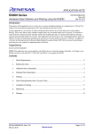
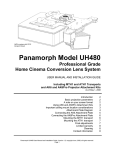
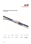
Version V1.0
VWCM-4000
CRACK METER
I
N
S
T
R
U
C
T
I
O
N
M
A
N
U
A
L
Version V1.0
2
Version V1.0
CONTENTS
Page
1.0
INTRODUCTION
4
1.1
1.2
General description
Theory of operation
4
5
2.0
CONFORMITY
6
3.0
MARKINGS
7
4.0
DELIVERY
8
4.1
4.2
4.3
4.4
Packaging
Handling
Inspection
Storage
8
8
8
9
5.0
5.1
5.2
5.3
5.4
5.5
5.6
INSTALLATION
Getting started
Preliminary tests
Setting distances
Installation - using re-bar anchors
Installation - using mechanical anchors
Installation - using welded anchors
10
10
11
12
13
18
23
6.0
6.1
6.1.1
6.1.2
6.2
6.3
6.3.1
DATA HANDLING
Taking readings
Portable readouts
Data loggers
Data reduction
Calibration certificate
Temperature considerations
Thermistor linearization
26
26
26
26
27
30
31
32
7.0
MAINTENANCE
33
8.0
TROUBLESHOOTING
33
9.0
SPECIFICATION
34
10.0
SPARE PARTS
36
11.0
RETURN OF GOODS
37
12.0
LIMITED WARRANTY
38
3
Version V1.0
1.0 INTRODUCTION
This manual is intended for all users of VWCM-4000 Crack Meters manufactured by
Geosense® and provides information on their installation, operation and maintenance.
It is VITAL that personnel responsible for the
installation and use of the VW Crack Meter READ and
UNDERSTAND the manual, prior to working with the
equipment.
1.1 General Description
A Vibrating Wire Crack Meter can be installed singly or included in many types of
monitoring regime and can be linked to various types of readout equipment.
The primary uses for Geosense® VWCM-4000 Cracks Meters are :Measure movement of Joints and behaviour of Cracks in Structures.
Measure Joint and Crack movement in Rock Faces
With applications such as, but not limited to, the following :Bridges
Dams
Tunnels
Buildings
Rock Faces
Mines
Particular features of the Geosense® VWCM-4000 Cracks Meters are:Reliable long term performance.
Rugged; suitable for demanding environments.
High accuracy.
Insensitive to long cable lengths.
The Frequency signals generated by Vibrating Wire instruments are particularly
suitable for the demanding environment of civil engineering applications. The signals
are capable of long transmission distances without degradation. They are also
somewhat tolerant of damp wiring conditions and resistant to interference from
external electrical noise.
The Geosense® range of VWCM-4000 Cracks Meters can be supplied in various
configurations to suit varying installation environments and techniques.
4
Version V1.0
1.1 General Description contd
Sensor cable
Vibrating Wire Coil &
Thermistor housing
Housing
Shaft
Top Rose joint (fixed)
Bottom Rose joint (adjustable)
1.2 Theory of Operation
The Geosense® VWCM-4000 Crack Meter is an stainless steel instrument that contains
a VW transducer that is connected to a Calibrated Spring which is in turn connected to
an extending shaft. The ends of the instrument are connected to either side of a crack or
joint so that, as structural movement occurs, the shaft is moved within the housing. The
shaft movement changes the tensions the spring which, in turn, changes the tension in
the vibrating wire. When interrogated, the vibrating wire in the transducer measures its
tension which can be converted to a linear displacement measurement in engineering
units, commonly millimetres.
The internal parts of all Geosense® VWCM-4000 Crack Meters are identical, only the
’Spring Rate’ of the spring and the length changes.
Within the Vibrating Wire transducer coil housing, two coils are located close to the axis
of the wire. When a voltage, or swept frequency excitation is briefly applied to the coils,
a magnetic field is created momentarily, causing the wire to oscillate at its’ resonant
frequency. The wire continues to oscillate for a short time through the ‘field’ of the
permanent magnet, thus generating an alternating current (sinusoidal) output. The
frequency of this current output is detected and processed by a vibrating wire readout
unit or by a data logger equipped with a vibrating wire interface. Readings can be
converted, by calculation, into ‘Engineering’ units.
5
Version V1.0
2.0 CONFORMITY
Geosense Limited
Nova House
Rougham Industrial Estate
Rougham, Bury St Edmunds
Email: [email protected]
Declaration of Conformity
We Geosense Ltd at above address declare under our sole responsibility that the Geosense products
detailed below to which this declaration relates complies with protection requirements of the following
harmonized EU Directives,
Low Voltage Directive 73/23/EEC (as amended by 93/68/EEC)
The Electromagnetic Compatibility Directive 2004/108/EC
The Construction Products Directive 89/106/EEC
Equipment description
Make/Brand
Model Numbers
VW Crack Meter
Geosense
VWCM-4000 Crack Meter Range
Compliance has been assessed with reference to the following harmonised standard:
EN 61326-1:2006 Electrical equipment for measurement, control and laboratory use.
EMC requirements. General requirements.
A technical file for this equipment is retained at the above address.
Martin Clegg
Director
June 2014
6
Version V1.0
3.0 MARKINGS
Geosense VW Crack Meter are labelled with the following information:Manufacturers name & contact details
Product name
Product Type
Operating Range
Serial number
Electrical Input & Output details
CE mark
7
Version V1.0
4.0 DELIVERY
This section should be read by all users of VWCM-4000 Crack Meters manufactured
by Geosense® .
4.1 Packaging
VWCM-4000 Crack Meters are packed for transportation to site. Packaging is
suitably robust to allow normal handling by transportation companies. Inappropriate
handling techniques may cause damage to the packaging and the enclosed
equipment. The packaging should be carefully inspected upon delivery and any
damage MUST be reported, as soon as possible, to both the transportation company
and Geosense.
4.2 Handling
Whilst they are a robust devices, VWCM-4000 Crack Meters are precision
measuring instruments. They and their associated equipment should always be
handled with care during transportation, storage and installation.
Once a shipment has been inspected, it is recommended that VWCM-4000 Crack
Meters remain in their original packaging for storage or further transportation.
Cable should also be handled with care. Do not allow it to be damaged by sharp
edges and do not exert force on the cable as this my damage the internal conductors
and could render an installation useless.
4.3 Inspection
It is important to check all the equipment in the shipment as soon as possible after
taking delivery and well before installation is to be carried out. Check that all the
components detailed on the documents are included in the shipment. Check that the
equipment has not been physically damaged.
ALL Geosense® VWCM-4000 Crack Meters carry a unique identification serial
number and are supplied with individual calibration sheets.
Calibration Sheets contain VITAL information about the VW
Crack Meter. They MUST be stored in a safe place.
It is suggested that only copies should be taken to site.
8
Version V1.0
4.4 Storage
All equipment should be stored in an environment that is protected from direct
sunlight. It is recommended that cables be stored in a dry environment to prevent
moisture migrating along inside them in the event of prolonged submersion of
exposed conductors.
Storage areas should be free from rodents as they have been known to damage
cables.
No other special requirements are needed for medium or long-term storage although
temperature limits should be considered when storing or transporting associated
components, such as readout equipment.
9
Version V1.0
5.0 INSTALLATION
This section of the manual is intended for all users of VWCM-4000 Crack Meters
manufactured by Geosense® and is intended to provide guidance with respect to
their installation.
It must be remembered that no two installations will be the same and it is inevitable
that some ‘fine tuning’ of the following procedures will be required to suit specific site
conditions.
It is VITAL that personnel responsible for the installation and use
of the VWCM-4000 Crack Meters READ and UNDERSTAND the
manual, prior to working with the equipment.
**********
As stated before, it is vital to check all the equipment in the shipment soon after
taking delivery and in good time before installation is to be carried out. Check that
all components that are detailed on the shipping documents are included.
5.1 Getting started - Preparation for Installation
Prior to installation of a VWCM-4000 Crack Meters it is essential to establish and
confirm details of the installation to be carried out. Some of the main considerations
are listed below :1.
Intended location and subsequent Protection
2.
Expected Movement of the Crack or Joint (see setting range)
3.
Anchoring Method
4.
Cable routing and marking
The end of the cables connected to VWCM-4000 Crack Meters is marked with the
unique serial number of the sensor to which it is attached.
All instrument cables should be marked with unique identification (e.g. colour codes).
Markings should be repeated at regular intervals along the cable where multiple
cables are to be grouped together, so that in the event of cable damage, there may
be a chance that the identification could be exposed and the cables re-joined
correctly. Multiple cable marks are particularly important close to the end of the
cable. The spacing of markings can vary according to specific site requirements but
a guide of 5m to 10m separation is commonly applied (marking materials available on
request from Geosense).
Cable routing must be carefully considered so as to ensure that it is not vulnerable
from intentional or accidental damage. Vibrating Wire signals can be affected by
electrical interference (EMI), so cable routing should AVOID close proximity to
possible sources.
10
Version V1.0
5.1 Getting started - Preparation for Installation contd...
Tools
Obtain any tools necessary to carry out the installation. The following is a brief list of
tools typically used during the installation of VWCM-4000 Crack Meters.
•
•
•
•
•
•
•
•
•
•
•
Wire cutters and strippers
Vibrating Wire Readout unit for setting the Crack Meter
Cable Marking system / equipment ( e.g. coloured PVC Tapes )
Marker Pen
Hammer Drill (mains for battery powered)
Drill Bit suitable for the materials into which the fixings will be fixed
Power Supply for the drill (if required)
Clean Cloth
Suitable resin bonding material
4mm & 5mm ‘Allen’ (hexagonal) keys.
Adjustable spanner
5.2 Preliminary tests
Before installing the VWCM-4000 Crack Meter, it
should be checked for proper operation.
Using a manual readout, such as a VW2106 (see
readout manual), select the B sweep range (1200 3550 Hz) and connect the signal wires as shown on the
right. Gently pull the shaft out to its, mechanical, full
extension stop. DO NOT TWIST THE ROD.
The readout should display an increasing reading up to
6700-7200 Digits. This value should be checked
against the Full Range reading on the individual
calibration certificate.
Gently allow the shaft to return into the housing making
sure that the pins on the shaft are aligned into the slot
on the housing.
Check the operation of the thermistor by holding the red
coil housing in your hand; the temperature reading on
the readout should slowly increase.
*NB If the readout display is in ‘Period’ units a calculation must be performed to convert from
Hertz2/1000 ( Linear Digits ) units, since the calibration sheet is presented in Hertz2/1000 units.
The Geosense Readout model VW200 displays the readings in ‘Period’. The RST readout /
logger unit Model Number VW2106 displays the readings in Linear Digits. See Section 6 of this
manual for more information about units and conversion routines.
DO NOT TWIST THE SHAFT OF THE CRACK METER
11
Version V1.0
5.3 Anchor spacing distance
The positioning of the fixing anchors (spacing distance) will depend on the range of the
crack meter and whether extension or compression is to be monitored. If this is unknown
gauges are typically set to mid-range.
The Table below shows the suggested anchor spacing distances for various operating
ranges and measurement configurations. If, for example, a crack meter is to be used to
measure only opening of a crack, we suggest that a 10% allowance for closing
(compression) is built into the spacing so that un-expected closing does not damage the
gauge. A similar principle is recommended for the spacing of anchors for crack closing
applications.
These are only recommendations and the user should decide what positions the
anchors are required to be set.
A portable readout and the individual calibration certificate must be used in conjunction with
the table below to determine/confirm the required anchor spacing.
50% of range (mm)
MONITOR
COMPRESSION
90% of range (mm)
MONITOR
EXTENSION
10% of range (mm)
5
228.3
230.5
226.0
12.5
246.6
252.3
241.0
25
300.3
311.5
289.0
50
343.5
366.0
321.0
75
447.8
481.5
414.0
100
492.0
537.0
447.0
150
640.5
708.0
573.0
200
795.0
885.0
705.0
300
1097.0
1232.0
962.0
500
1704.0
1929.0
1479.0
RANGE
(mm)
MID RANGE
All of the above are approximate dimensions and the setting, ‘centre to centre’ distance on
the crack meter may need to be adjusted using the Rose joint on the end of the shaft.
12
Version V1.0
5.4 Installation - using Re-bar anchors
INSTALLATION TEMPLATE
It is recommended to make and use a ‘site specific’ spacing template for the following
reasons:• Maintains a consistent setting distance between the anchors
• Makes marking of drill holes easier
• Helps keep anchors in place during the curing of the fixing resin
Typical materials that can be used to make the template are wood, steel or plastic.
Obviously if the material is soft ( wood / plastic ) it will wear more with use.
1.
Cut a suitable piece of bar for use as a
template. Carefully mark the centres of the
holes that correspond to the position of the
fixing holes.
Drill one 5mm and one 6mm hole in the
template.
2.
Clear the intended location of debris or dust.
3.
Using the template, mark the hole centres to
be drilled.
Using a suitable masonry drill bit, drill a pilot
hole in the locations marked.
4.
Select a suitable masonry drill bit for the
groutable anchors that are to be used.
12mm rebar use 18mm drill bit
16mm rebar use 20mm drill bit
5.
Measure the required depth to be drilled and
set a stop on drill so that hole is drilled to the
required depth.
13
Version V1.0
5.4 Installation - using Re-bar anchors contd...
6.
Drill both holes to the required depth.
BE SURE NO ELECTRICAL CABLES OR OTHER SERVICES
ARE DIRECTLY BELOW SURFACE TO BE DRILLED
7.
Cleaning out the drill holes before inserting
bonding resin is essential . A small brush is
a good tool for cleaning out the loose debris
and the bicycle pump is good for blowing out
the dust so that the resin can adhere well to
the inner walls of the hole.
8.
To install the groutable anchors will require a
gauge template plus suitable fixing resin* and
applicator gun ( if necessary ).
14
Version V1.0
5.4 Installation - using Re-bar anchors contd...
9.
Attach the anchors to the template with the M5
and M6 screws supplied, as shown.
SELECT A NON-SHRINKING RIGID
RESIN SUITABLE FOR THE
MATERIAL INTO WHICH ANCHORS
ARE BEING PLACED
10. Thoroughly mix an adequate amount of resin
and fill the anchor holes.
Where a resin cartridge is being used, insert
the cartridge nozzle into the base of the holes
and fill from the base upwards.
11. Insert the groutable anchors to the required
depth, rotating them to ensure a good bond.
Leave the resin to cure for the time stated in
the product manufacturer’s instructions.
15
Version V1.0
5.4 Installation - using Re-bar anchors contd...
12. Once the resin has hardened remove the
securing screws.
13. Fix the M6 bolt through the Rose joint on the
transducer end of the crack meter and into the
rebar anchor.
14. Fit the M5 bolt through the Rose joint on the
shaft end of the gauge and carefully extend
the shaft. Fix the screw into the anchor but do
not tighten it. A reading of the gauge should
be taken to ascertain correct setting before the
bolts are fully tightened.
15. Check the reading on the readout to ensure
that it is at approximately the value that
corresponds to the extension required.
This should be checked against the individual
calibration sheet for the Crack meter being
installed.
16
Version V1.0
5.4 Installation - using Re-bar anchors contd...
16. If the reading/setting distance is not in the
correct range then adjustments can be made
to the threaded Rose joint on the shaft of the
crack meter. To adjust, undo M5 bolt and
carefully remove Rose joint from the anchor.
Ensure that the Rose joint locking nut is loose
and turn the Rose joint clockwise to lower the
crack meter readings and anticlockwise to
raise the readings.
DO NOT ROTATE THE SHAFT
17. When the reading is correct remove the fixing
and carefully allow the crack meter to close,
ensuring the alignment pins engage with the
slots on the housing tube.
Tighten the locking nut to ensure that the rose
joint is tight.
18. Re-fix the crack meter to the anchor and
tighten the screw using the Allen key.
The crack meter is now installed. Its readout cable
can be routed to a convenient location for
termination or to a data logger location.
It is strongly recommended that the crack meter is
fitted with a lined protective cover to reduce the
risk of damage and reduce the effects of
temperature changes.
ONCE INSTALLED AND THE CRACK METER’S
TEMPERATURE HAS STABILISED, IT IS IMPORTANT TO
ESTABLISH INITIAL READINGS.
ALL SUBSEQUENT READINGS WILL BE REFERENCED
TO THESE INITIAL READINGS
17
Version V1.0
5.5 Installation - using mechanical type anchors
INSTALLATION TEMPLATE
It is recommended to make and use a ‘site specific’ spacing template for the following
reasons:• Maintains a consistent setting distance between the anchors
• Makes marking of drill holes easier
Typical materials that can be used to make the template are wood, steel or plastic.
Obviously if the material is soft ( wood / plastic ) it will wear more with use.
1. First gather all the components and tools
together. For this type of installation, this will
include:
Template
Hammer Drill
Suitable Drill Bit(s)
10 and 13mm spanners
Hammer
Adjustable spanner
4mm and 5mm Allen Keys
Anchors
Mounting blocks
Gauge with Rose joint ends
2. Clear the installation area and mark the
position of the fixings using the template.
3. Set the depth gauge on the drill to the required
depth.
18
Version V1.0
5.5 Installation - using mechanical type anchors - cont...
4. Drill the holes for the anchors
BE SURE NO ELECTRICAL CABLES OR OTHER SERVICES
ARE DIRECTLY BELOW SURFACE TO BE DRILLED
5. Clean out the drill hole to ensure it is free from
dust. A bicycle pump is useful here.
6. Install the anchors - as anchor types differ, the
fixing of the anchors will vary.
19
Version V1.0
5.5 Installation - using mechanical type anchors - cont...
7. Tighten any securing nuts / bolts to ensure that
the fixing does not move
8. Fit both the mounting blocks to the anchors.
Remember that one end has a larger and one
a smaller threaded crack meter mounting.
Use the second nut on the fixing to ‘lock’ the
mounting block onto the anchor.
9. Ensure that the larger Rose joint end is firmly
attached to the Crack meter by checking that it
fully tightened up to its locking nut.
20
Version V1.0
5.5 Installation - using mechanical type anchors - cont...
10. Fit the larger end of the crack meter ( sensor
end ) to its mounting using the M6 bolt.
11. Tighten the bolt using the 5mm Allen key ( use
a spanner on the locking nut as a tightening
reaction )
12. Check that smaller Rose joint is screwed into
the other end of the Crack meter. ( it is best to
screw it fully into Crack meter and then unscrew it by 4 turns, leaving the locking nut
loose, at this stage.
Carefully draw the end of the transducer out
and fit it the mounting block, using the M5
screw.
13. Check the reading on the readout to ensure
that it is at approximately the value that
corresponds to the extension required.
This should be checked against the individual
calibration sheet for the Crack meter being
installed.
21
Version V1.0
5.5 Installation - using mechanical type anchors - cont...
14. If the reading/setting distance is not in the
correct range then adjustments can be made
to the threaded Rose joint on the shaft of the
crack meter. To adjust, undo M5 bolt and
carefully remove Rose joint from the anchor.
Ensure that the Rose joint locking nut is loose
and turn the Rose joint clockwise to lower the
crack meter readings and anticlockwise to
raise the readings.
DO NOT ROTATE THE SHAFT
15. When the reading is correct remove the fixing
and carefully allow the gauge to close,
ensuring the alignment pins engage with the
slots on the housing tube.
Tighten the locking nut to ensure that the rose
joint is tight.
16. Re-fix the gauge to the anchor and tighten the
screw using the Allen key and a spanner on
the anchor locking nut.
The crack meter is now installed. Its readout cable
can be routed to a convenient location for
termination or to a data logger location.
It is strongly recommended that the crack meter is
fitted with a lined protective cover to reduce the
risk of damage and reduce the effects of
temperature changes.
ONCE INSTALLED AND THE CRACK METER’S
TEMPERATURE HAS STABILISED, IT IS IMPORTANT TO
ESTABLISH INITIAL READINGS.
ALL SUBSEQUENT READINGS WILL BE REFERENCED
TO THESE INITIAL READINGS
22
Version V1.0
5.6 Installation - using Welded anchors
INSTALLATION TEMPLATE
It is recommended to make and use a ‘site specific’ spacing template for the following
reasons:•
Makes marking of mounting positions easier
•
Can be used to support the anchor blocks during welding
Typical materials that can be used to make the template are wood, steel or plastic.
Obviously if the material is soft ( wood / plastic ) it will wear / melt with use.
1. First gather all the components and tools
together. For this type of installation, this will
include:
Template
10 mm spanner
Adjustable spanner
4mm and 5mm Allen Keys
Mounting blocks
Gauge with Rose joint ends
Welding Equipment
2.
Clear the installation area and mark the
position of the fixings using the template.
3.
Weld the mounting blocks in the required
position.
23
Version V1.0
5.6 Installation - using Welded anchors - cont….
4. Ensure that the larger Rose Joint end is firmly
attached to the Crack meter by checking that it
fully tightened to its locking nut.
5.
Fit the larger end of the crack meter ( sensor
end ) to its mounting, using the M6 bolt
through the Rose joint, and tighten the Allen
screw.
6.
Slide the M5 bolt through the mounting hole on
the Rose joint on the shaft end of the crack
meter. Carefully draw the shaft out and fix it to
the other anchor, but do not tighten reading of
the gauge should be taken to ascertain correct
setting before the bolts are fully tightened.
7.
Check the reading on the readout to ensure
that it is at approximately the value that
corresponds to the extension required.
This should be checked against the individual
calibration sheet for the Crack meter being
installed.
24
Version V1.0
5.6 Installation - using Welded anchors - cont….
8.
If the reading/setting distance is not in the
correct range then adjustments can be made
to the threaded Rose joint on the shaft of the
crack meter. To adjust, undo M5 bolt and
carefully remove Rose joint from the anchor.
Ensure that the Rose joint locking nut is loose
and turn the Rose joint clockwise to lower the
crack meter readings and anticlockwise to
raise the readings.
DO NOT ROTATE THE SHAFT
9. When the reading is correct remove the fixing
and carefully allow the gauge to close,
ensuring the alignment pins engage with the
slots on the housing tube.
Tighten the locking nut to ensure that the rose
joint is tight.
10. Re-fix the gauge to the anchor and tighten the
screw using the Allen key and a spanner on
the anchor locking nut.
The crack meter is now installed. Its readout cable
can be routed to a convenient location for
termination or to a data logger location.
It is strongly recommended that the crack meter is
fitted with a lined protective cover to reduce the
risk of damage and reduce the effects of
temperature changes.
ONCE INSTALLED AND IT’S TEMPERATURE
STABILISED, IT IS IMPORTANT TO ESTABLISH INITIAL
READINGS.
ALL SUBSEQUENT READINGS WILL BE REFERENCED
TO THESE INITIAL READINGS
25
Version V1.0
6.0 DATA HANDLING
The function of an instrument is to provide useful and reliable data.
Accurate recording and handling of the data is essential if it is to be
of any value.
6.1 Taking readings
6.1.1 Portable Readouts
Geosense® offer a range of readout and data logging options. Specific operation
manuals are supplied with each readout device.
Below is a brief, step-by-step procedure for use with the VW2106 portable readout.
1.
Connect signal cable from the sensor to the readout following the wiring colour
code. Conductor colours may vary depending upon the extension cable used.
Commonly these are:
RED
BLACK
GREEN
WHITE
=
=
=
=
VW +
VW Temp
Temp
2.
Switch on the unit and, where necessary,
select range B
3.
The readout displays the Vibrating Wire
reading ( in Hz2/1000 - Linear Digits ) and a
temperature reading in degrees C.
Whilst it is not critical that the polarity be observed
for most Vibrating Wire instruments, a better signal
may be obtained if the correct polarity is adopted. Since the temperature sensor is a
Thermistor, its connection polarity is not important.
6.1.2 Data Loggers
A number of data loggers are available to automatically excite, interrogate and record
the reading from Vibrating Wire instruments. These include devices manufactured
and supplied by Geosense in both single and multi-channel configurations, as well as
equipment manufactured by other suppliers.
Geosense configures and supply's equipment manufactured by both Campbell
Scientific Ltd and DataTaker Ltd. These are the most commonly adopted third party
manufacturers of data loggers that can be used with Vibrating Wire Instruments.
Specific configuration and programming advice can be obtained from Geosense and/
or the manufacturers documentation.
26
Version V1.0
6.2
Data Reduction
Overview
Readings from a crack meter are in a form that is a function of frequency, rather than
in units of distance. Commonly the units would be either Frequency - Hertz (Hz),
Linear - Hz2/1000 or Hz2/1000000 or Period - Time - (Seconds x10-2 or x10-7).
To convert the readings to units of distance, calibration factors must be applied to the
recorded values. For most Vibrating Wire sensors, these factors are unique and are
detailed on the sensor calibration sheet. A unique calibration sheet is supplied with
each Geosense VW crack Meter. An example of the calibration sheet is shown on
page 39.
If the readout display is in Period units ( e.g. 0.03612 or 3612 - depending upon the
readout used ) the first step to producing an engineering value is to convert the
readings to Linear Digits ( Hz2/1000 ) . Two examples of this calculation can be seen
below. The first (1) where the readout includes a decimal point and displays the
Period in Seconds–2 and the second (2) where the readout displays the Period in
Seconds-7
(1)
Readout Display
Linear Digits (Hz2/1000)
=
=
=
0.03612
( 1 / 0.03612 –2 ) 2 / 1000
7664.8
(2)
Readout Display
Linear Digits (Hz2/1000)
=
=
=
3612
( 1 / 3612 –7 ) 2 / 1000
7664.8
If the readout displays ‘Frequency’ values, ( e.g. 2768.5 Hz ) only a simple calculation
is required to convert the readings to ‘Linear Digits’.
Linear Digits (Hz2/1000)
=
=
( 2768.5 ) 2 / 1000
7664.6
Certain data loggers store their Vibrating Wire data in Linear Digits but further divided
by 1000. In this case the data would have to be multiplied by 1000 to maintain the
standard Linear Digits (Hz2/1000) format for the standard calculations.
There are many ways to achieve the conversion from recorded data to useful
engineering values. The following are included as a guide only and as a basis for
alternative approaches.
Linear Calculation
This is the most straight forward calculation to convert ‘raw’ data to engineering units.
It requires that the readings are in Linear Digits (Hz2/1000) and it can be easily
carried out using a simple calculator. Where this is not the case, the readings must
27
Version V1.0
be converted to Linear Digits prior to computation.
For most applications this equation is perfectly adequate and is carried out as
follows:
Displacement (mm) = Linear Factor (K for mm) x (Current Reading - Initial Reading)
Polynomial Calculation
In some instances, this calculation can be slightly more precise as it accommodates
some slight deviation of the data from a straight line calibration. However, in its
standard form, it does not easily accommodate site recorded base readings or
environmental changes that may affect the zero or initial value (such as altitude).
Displacement ( mm ) =
[ Factor A for mm x (Reading)2 ] + [ Factor B for mm x Reading]+ Factor C for mm
The instrument calibration sheet similar to the example on page 31 of this manual
includes the following information:
Model
Serial
Works ID
Cable m
Readout No.
R/O Cal Date
Cal Date
Master
Temp oC
Batch
Range mm
Ap. Displacement
Hz2 * 10-3
Ind. Displacement
Lin. Error % FSO
Poly. Error % FSO
Deviation
Hysteresis
Calibration Factors
This refers to the Geosense model number.
This is a unique sensor identification number that can be found
on the body of the crack meter and, for long cables, at the end
of the cable.
Unique works code
Length of cable fitted
Serial Number of the readout used to display the crack meter
output
The date on which the Readout was calibrated to a traceable
standard
Date the calibration of the crack meter was performed
Serial number of the Master Transducer used for the
calibration
Temperature at which the unit was calibrated
Works batch number
Operating range of the crack meter
Displacement applied to the transducer as part of the
calibration cycle in mm
Readings from the crack meter as movement is applied and
reduced, in steps. The average is calculated.
Calculation of the displacement using the calculated Linear
and Polynomial equations.
Non Linearity expressed as a percentage of the crack meters
Full Scale.
Non Linearity expressed as a percentage of the crack meters
Full Scale.
Non Linearity expressed in Digits (Hz2/1000)
Difference between increasing and decreasing readings as a
percentage of the crack meters Full Scale.
‘Linear’ and ‘Polynomial’ factors are provided for a selection of
28
Version V1.0
(Continued from page 28)
Engineering units ( other units can be calculated directly from the mm values ).
Examples of calculated values are detailed below.
The following are examples of data reduction calculations and are based upon the
crack meter to which the attached example calibration sheet refers. The results are
displayed as ‘change in distance’ in millimetres
A.
An example of the calculation from Period units (Seconds –7) to mm using a
Linear equation is given below:Site Initial Reading (period units)
Initial Converted to Linear Digits
Calibration Factor for mm (K)
= 5142
= 3782
= 0.012218561
Current Reading (period units)
Current Converted to Linear Digits
= 4282
= 5454.8
Equation
Displacement in mm
Displacement in mm
Displacement in mm
B.
= K x ( Current Reading - Initial Reading )
= 0.012218561x ( 5454.8 - 3782.0 )
= 20.44 mm
An example of the calculation from Linear Digits ( Hz2/1000) to mm using a
Polynomial equation is given below:Calibration Factors for mm
A
B
C
Current Reading in Linear Digits
= 3.9746 -8
= 0.011820338
= - 35.375
= 5454.8
Equation
Displacement in mm = [ A x ( Reading )2 ] + [ B x Reading ] + C
= [ 3.9746 -8 x (5454.8)2] + [ 0.011820338 x 5454.8] - 35.375
= 1.183 + 64.477 - 35.375
= 30.29 mm
‘Linear’ calculations require the establishment of an Initial reading on site after the
crack meter has been installed and its temperature stabilised. This is often
considered the most representative approach since the value is established on site
and in its operating environment.
‘Polynomial’ calculations produce a displacement value related to the ‘Zero’
displacement established in the factory during the calibration process.
(Continued on page 30)
29
GEOSENSE QUALITY FORM
FORM No G/QF/125
ISS.
2
DATE : MAY13
SIG. GC
VIBRATING WIRE DISPLACEMENT TRANSDUCER CALIBRATION
Model
Serial
Works ID
Cable m
Readout No.
VWDT 5000
505660
69
0
VR0601
R/O Cal.Date
13/07/2012
Applied
Displacement
mm
0.00
10.00
20.00
30.00
40.00
50.00
2
-3
Hz *10
1 up
2961.0
3792.0
4614.0
5432.0
6247.0
7056.0
5-Apr-13
20162
19
65
50
Cal date
Master
Temp oC
Batch
Range mm
1 down Avg. Digit
2964.0 2962.5
3792.0 3792.0
4612.0 4613.0
5429.0 5430.5
6245.0 6246.0
7055.0 7055.5
Indicated
Displacement
(mm)
Linear
Poly.
-0.10
-0.01
10.04
10.02
20.07
20.00
30.06
29.99
40.02
40.00
49.91
50.00
Linear
Error
% FSO
-0.20%
0.07%
0.14%
0.11%
0.04%
-0.18%
Polynomia
Deviation Hysteresis
l Error
% FSO
-0.02%
0.04%
-0.01%
-0.03%
0.01%
0.00%
Digit
-3
0
2
3
2
1
Calibration of master 20162 [Equip. No. 011] valid from 09 May 2013, by Geosense Ltd
CALIBRATION FACTORS
Linear factor k (mm)
Polynomial factors (mm)
mm / digit
mm / digit
0.012218561
A
B
C
3.9746E-08
0.011820338
-35.3756091
Users must establish site zero base readings for Linear calculation purposes
Linear calculation [mm] = k (mm) * (Current Reading - Site Zero Reading)
Polynomial calculation [mm] = A * (Reading)2 + B * (Reading) + C
Note: Readings are taken in frequency squared units.
Please refer to User Manuals if reading in period or frequency units
THIS CERTIFICATE IS VALID ONLY WHEN CARRYING THE
OFFICIAL ORIGINAL STAMP OF GEOSENSE
%
-0.07
0.00
0.05
0.07
0.05
0.02
Version V1.0
6.3 Temperature Considerations
Geosense® VWCM-4000 Crack Meters include temperature sensors. Where a
crack meter are installed in a zone where its temperature is likely to fluctuate
significantly, records of temperature data should be recorded. This can then be used
to assess any temperature effects on the crack meter readings and on the structure
being monitored . Readings from readouts can be in either Engineering units or
resistance (see thermistor linearization on page 32).
The Thermal influences on crack meter readings are often complex. Therefore, in
order to apply any correction for temperature changes it is first necessary to establish
the effects of temperature changes on a particular crack meter and, more importantly,
on the structure to which it is attached.
To establish the true affects of temperature changes, it is necessary to observe the
readings from a particular crack meter over a period of thermal change, when little or
no structural changes are taking place. This helps to identify the overall effects on
the crack meter, the material on which it is mounted and the structure as a whole.
To minimise the effects of rapid temperature changes ( thermal shock ) it is advisable
to fit a protective thermal cover over the installation. This will reduce the risk of
thermal gradients over the crack meter itself when the temperature changes rapidly
(e.g. sun strike).
31
Version V1.0
6.3.1Thermistor Linearization
USING STEINHART & HART LOG
Thermistor Type. YSI 44005, Dale 1C 3001 B3, Alpha 13A3001-B3
Resistance/ temperature equation:T= (1 / (A + B (LnR) + C(LnR) 3)) –273.2
Where:T = Temperature in degrees Centigrade
LnR= Natural log of Thermistor resistance.
A= 1.4051* 10-3
B= 2.369*10-4
C=1.019*10-7
Resistance versus temperature table
Ohms
Temp
Ohms
Temp
Ohms
Temp
Ohms
Temp
Ohms
Temp
201.1K
187.3K
174.5K
162.7K
151.7K
141.6K
132.2K
123.5K
115.4K
107.9K
101.0K
94.48K
88.46K
82.87K
77.66K
-50
-49
-48
-47
-46
-45
-44
-43
-42
-41
-40
-39
-38
-37
-36
16.60K
15.72K
14.90K
14.12K
13.39K
12.70K
12.05K
11.44K
10.86K
10.31K
9796
9310
8851
8417
-10
-9
-8
-7
-6
-5
-4
-3
-2
-1
0
1
2
3
2417
2317
2221
2130
2042
1959
1880
1805
1733
1664
1598
1535
1475
1418
30
31
32
33
34
35
36
37
38
39
40
41
42
43
525.4
507.8
490.9
474.7
459.0
444.0
429.5
415.6
402.2
389.3
376.9
364.9
353.4
342.2
70
71
72
73
74
75
76
77
78
79
80
81
82
83
153.2
149.0
145.0
141.1
137.2
133.6
130.0
126.5
123.2
119.9
116.8
113.8
110.8
107.9
110
111
112
113
114
115
116
117
118
119
120
121
122
123
72.81K
68.30K
-35
-34
8006
7618
7252
4
5
6
1363
1310
1260
44
45
46
331.5
321.2
311.3
84
85
86
105.2
102.5
99.9
124
125
126
64.09K
60.17K
56.51K
53.10K
49.91K
46.94K
44.16K
41.56K
-33
-32
-31
-30
-29
-28
-27
-26
6905
6576
6265
5971
5692
5427
5177
4939
7
8
9
10
11
12
13
1212
1167
1123
1081
1040
1002
965.0
47
48
49
50
51
52
53
301.7
292.4
283.5
274.9
266.6
258.6
250.9
87
88
89
90
91
92
93
97.3
94.9
92.5
90.2
87.9
85.7
83.6
127
128
129
130
131
132
133
39.13K
36.86K
34.73K
32.74K
30.87K
29.13K
27.49K
25.95K
24.51K
23.16K
21.89K
20.70K
19.58K
18.52K
17.53K
-25
-24
-23
-22
-21
-20
-19
-18
-17
-16
-15
-14
-13
-12
-11
4714
4500
4297
4105
3922
3748
3583
3426
3277
3135
3000
2872
2750
2633
2523
14
15
16
17
18
19
20
21
22
23
24
25
26
27
28
29
929.6
895.8
863.3
832.2
802.3
773.7
746.3
719.9
694.7
670.4
647.1
624.7
603.3
582.6
562.8
543.7
54
55
56
57
58
59
60
61
62
63
64
65
66
67
68
69
243.4
236.2
229.3
222.6
216.1
209.8
203.8
197.9
192.2
186.8
181.5
176.4
171.4
166.7
162.0
157.6
94
95
96
97
98
99
100
101
102
103
104
105
106
107
108
109
81.6
79.6
77.6
75.8
73.9
72.2
70.4
68.8
67.1
65.5
64.0
62.5
61.1
59.6
58.3
56.8
134
135
136
137
138
139
140
141
142
143
144
145
146
147
148
149
32
Version V1.0
7.0
MAINTENANCE
The VWCM-4000 Crack Meter is a maintenance free device for most applications. This
is because it is intended for installation in areas that may normally be inaccessible.
Where accessible, the primary maintenance issue would be to ensure that it is free from
the build up of debris and dust that may affect its performance.
In addition, where the units can be safely removed from their mountings and a need
arises, these instruments can be re-calibrated by Geosense.
Maintenance of wiring connections between the VWCM-4000 Crack Meter and any
terminal panels / or loggers should involve occasional tightening of any screw terminals to
prevent loose connections or cleaning to prevent the build up of corrosion.
8.0 TROUBLESHOOTING
It is generally accepted that when a Vibrating Wire instrument is producing a stable
reading on a suitable readout, the value will be correct. Only on very rare occasions will
this be untrue.
In almost all cases, a fluctuating reading is a sign of a faulty signal from the sensor.
However, the fault could be in either the sensor, the connecting cable, any switch boxes
or the readout. The best way to fault find an instrument is to isolate it from all other
instruments and connections. Where possible begin fault finding from as close to the
sensor as is possible.
A fault finding flow diagram is included on the next page, to help with troubleshooting.
33
Version V1.0
8.0 TROUBLESHOOTING - cont.
34
Version V1.0
9.0 SPECIFICATION
VWCM-4000 Crack Meter
Range
5, 12.5, 25, 50, 100, 150, 200, 300, 500mm
Resolution
<0.025% FS
Accuracy
±0.1 to ±0.5% FS
Non-linearity
<0.5% FS
Frequency range
1650-2700 Hz
Nominal zero value
1850 Hz
Body material
Stainless steel
Inner rod
Stainless steel
O-ring
Viton
Anchor material
Mild steel, BZP
Anchor types
Grout, bond, bolt, arc weld, expandable
Waterproof rating
16 bar
Cable
2 pair PUR sheath
CHEMICAL METAL*
PRODUCT DESCRIPTION
Universal fix-it product, which joins, fills, seals and replaces metal, wood, stone etc.
Sets hard in 10 minutes.
Performance of cured material
Electrical conductivity (Ω/cm)
Hardness (Shore D)
Tensile strength (N/mm2)
Compressive strength (N/mm2)
Adhesion Mild steel
1014
85-90
~16
~90
< +160 °C
Chemical resistance
Cured material is resistant to water, salt solutions, organic solvents,
diluted acids and alkalis
OTHER SIMILAR BONDING MATERIALS HAVING SIMILAR PROPERTIES WILL BE
SUITABLE FOR THIS APPLICATION
* Chemical Metal is a Loctite product
35
Version V1.0
10.0 SPARE PARTS
As a VWCM-4000 Crack Meter is a sealed unit, it is neither serviceable nor does it
contain any replaceable parts.
Civil engineering sites are hazardous environments and instrument cables can be easily
damaged if they are not adequately protected. Geosense can therefore provide the
following parts that may be required to effect repairs to instrument cables:
•
PU coated 4 Core cable with foil shield and copper drain.
•
PVC coated, armoured, 4 Core cable suitable for direct burial.
•
Epoxy jointing kit for forming a waterproof cable joint.
•
Replacement anchors and ‘Rose joints’
Please contact Geosense for price and availability of the above components.
36
Version V1.0
11.0 RETURN OF GOODS
11.1 Returns procedure
If goods are to be returned for either service/repair or warranty, the customer should
contact Geosense Ltd for a Returns Authorisation Number, request a Returned
Equipment Report Form QF034 and, prior to shipment. Numbers must be clearly
marked on the outside of the shipment.
Complete the Returned Equipment Report Form QF034, including as much detail as
possible, and enclose it with the returned goods and a copy of the form should be faxed
or emailed in advance to the factory.
11.2 Chargeable Service or Repairs
Inspection & estimate
It is the policy of Geosense Ltd that an estimate is provided to the customer prior to any
repair being carried out. A set charge for inspecting the equipment and providing an
estimate is also chargeable.
11.3 Warranty Claim
(See Limited Warranty Conditions)
This covers defects which arise as a result of a failure in design or manufacturing. It is a
condition of the warranty that the VWCM-4000 Cracks Meters must be installed and
used in accordance with the manufacturer’s instructions and has not been subject to
misuse.
In order to make a warranty claim, contact Geosense Ltd and request a Returned
Equipment Report Form QF034. Tick the warranty claim box and return the form with
the goods as above. You will then be contacted and informed whether your warranty
claim is valid.
11.4 Packaging and Carriage
All used goods shipped to the factory must be sealed inside a clean plastic bag and
packed in a suitable carton. If the original packaging is not available, MGS Geosense
should be contacted for advice. Geosense Ltd will not be responsible for damage
resulting from inadequate returns packaging or contamination under any circumstances.
11.5 Transport & Storage
All goods should be adequately packaged to prevent damage in transit or intermediate
storage.
37
Version V1.0
12.0 LIMITED WARRANTY
The manufacturer, Geosense Ltd warrants the VWCM-4000 Cracks Meters
manufactured by it, under normal use and service, to be free from defects in material and
workmanship under the following terms and conditions:Sufficient site data has been provided to Geosense Ltd by the purchaser as regards the
nature of the installation to allow Geosense Ltd to select the correct type and range of
VWCM-4000 Cracks Meters and other component parts.
The VWCM-4000 Cracks Meters equipment shall be installed in accordance with the
manufacturer’s recommendations.
The equipment is warranted for 1 year from the date of shipment from the manufacturer
to the purchaser.
The warranty is limited to replacement of part or parts which, are determined to be
defective upon inspection at the factory. Shipment of defective part or parts to the factory
shall be at the expense of the Purchaser. Return shipment of repaired/replaced part or
parts covered by this warranty shall be at the expense of the Manufacturer.
Unauthorised alteration and/or repair by anyone which, causes failure of the unit or
associated components will void this LIMITED WARRANTY in its entirety.
The Purchaser warrants through the purchase of the (insert product type)
equipment that he is familiar with the equipment and its proper use. In no event
shall the manufacturer be liable for any injury, loss or damage, direct or
consequential, special, incidental, indirect or punitive, arising out of the use of or
inability to use the equipment sold to the Purchaser by the Manufacturer.
The Purchaser assumes all risks and liability whatsoever in connection with the
VWCM-4000 Cracks Meters equipment from the time of delivery to Purchaser.
38
Version V1.0
NOTES:
.
39
Version V1.0
Nova House . Rougham Industrial Estate . Rougham . Bury St Edmunds . Suffolk . IP30 9ND . England .
Tel: +44 (0) 1359 270457 . Fax: +44 (0) 1359 272860 . email: [email protected] . www.geosense.co.uk
40