1
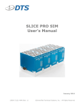
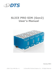
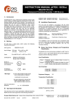
SLICE PRO Ethernet Controller User’s Manual May 2015 13000-30610-MAN (Rev. 3) © Diversified Technical Systems, Inc. - All Rights Reserved SLICE PRO Ethernet Controller User’s Manual May 2015 Table of Contents DTS Support ....................................................................................................................... 3 Introducing the SLICE PRO Ethernet Controller ............................................................. 4 SLICE PRO Ethernet Controller Control Panel ................................................................ 4 LED Indicators ................................................................................................................. 5 Using the ON Power Switch ............................................................................................. 5 Remote ON .................................................................................................................. 5 Using the PWR Input ....................................................................................................... 6 Using the COM A and COM B Connectors ...................................................................... 6 Basic Care and Handling ................................................................................................... 7 Shock Rating.................................................................................................................... 7 Mounting Considerations ............................................................................................. 7 Thermal Considerations ................................................................................................... 7 Power Management............................................................................................................ 8 Power Consumption ......................................................................................................... 8 Internal Battery................................................................................................................. 8 Power-up and Power-down Procedures .......................................................................... 9 Communication Features .................................................................................................. 9 Communication Method ................................................................................................... 9 Using Multiple SLICE PRO Ethernet Controllers ....................................................... 10 Changing the IP Address ........................................................................................... 10 Auxiliary Signals ............................................................................................................. 11 Start Record Input...................................................................................................... 11 Status Output Signal .................................................................................................. 11 Using the Event Input ...................................................................................................... 12 Appendix A: Connector Information.............................................................................. 13 Appendix B: Mechanical Specifications........................................................................ 14 Accessories/Support Equipment .................................................................................... 15 Appendix C: Hardware Configuration Specifications .................................................. 16 support.dtsweb.com ii 13000-30610-MAN (Rev. 3) SLICE PRO Ethernet Controller User’s Manual May 2015 DTS Support SLICE PRO systems are designed to be reliable and simple to operate. Should you need assistance, DTS has support engineers worldwide with extensive product knowledge and test experience ready to help via telephone, e-mail or on-site visits. The best way to contact a DTS support engineer is to submit a request through the DTS Help Center web portal (support.dtsweb.com). You must be registered (support.dtsweb.com/registration) to submit a request (https://support.dtsweb.com/hc/enus/requests/new). Registration also enables access to additional self-help resources and non-public support information. This manual supports the following products: 13000-30610: SLICE PRO Ethernet Controller (Gen3) support.dtsweb.com 3 13000-30610-MAN (Rev. 3) SLICE PRO Ethernet Controller User’s Manual May 2015 Introducing the SLICE PRO Ethernet Controller The SLICE PRO Ethernet Controller is a communications and signal interface for a SLICE PRO system. It supports event, start record and status signals, and is compatible with all SLICE PRO and TDAS COM connectors. It supports up to 4 SLICE PRO modules, including the SLICE PRO SIM. Shock hardened to 100 g for dynamic testing environments. Ethernet 10/100BaseT/Tx communications that supports daisy-chained SLICE PRO systems up to 500 channels. Internal battery with 1 hour capacity functions as primary or back-up power. LED indicators for power and system status. Primary system input power via the power input connector is protected against reverse current, over-current, and limited transient over-voltage conditions. Compatible with SLICE PRO and TDAS equipment via the COM connectors. Contact-closure event input with 1000 V isolation. Integral threaded mounting holes. SLICE PRO Ethernet Controller Control Panel The two 19-pin COM connectors are functionally identical and allow access to all communication features and signal lines. The PWR connector supports primary system input power and the ON power switch will power up or power down the system. See Appendix A for connector information and pin assignments. Mechanical specifications are included in Appendix B. Appendix C identifies the network parameters of your equipment. COM A and COM B - Functionally identical - To PC via REC cable (P/N 10700-0015x) - Supports Ethernet 10/100BaseT/ Tx communications, event input, remote on, start record input and status signals - Compatible with all TDAS and SLICE PRO COM connectors PWR power input connector (See table on next page) ON power switch - Cycles power ON/OFF - Momentary; firmly press and hold for 2 sec STS LED (See table on next page) PWR LED (See table on next page) SLICE PRO Ethernet Controller Control Panel support.dtsweb.com 4 13000-30610-MAN (Rev. 3) SLICE PRO Ethernet Controller User’s Manual May 2015 LED Indicators There are two LED indicators that provide system status. The status LED indicates communication and arm status, and the power LED indicates power status. LED behavior is summarized in the tables below. State Idle or no power input Armed in Recorder mode and waiting for Start Record signal to begin data collection Recording; status line low Recording; status line high Communicating with PC (not armed) System Power ON System Power OFF Power up Connected to external power and unit is charging (power OK) Connected to external power and unit is charging (power OK) Connected to external power and unit has fully charged Battery low Connected to external power; power fault Using the ON Power Switch A low-profile piezo switch is used for on/off control. There is no detectable movement in the switch; you must press and hold firmly for 2 seconds to start or stop the system. The PWR LED will blink blue when the system is initializing and go solid blue when ready. Total time from ON initiation to system ready is typically between 1-2 minutes. Multiple units in a chain may be started in any order. When all units are ready and showing solid blue LEDs, you may start the software. Be sure to follow proper procedures to avoid an unstable condition. Remote ON A SLICE PRO system may be powered on and off remotely via the COM connectors. This has the same effect as using the ON power switch. The system will power up and remain on as long as the signal is applied and will power down when the signal is removed. To use this feature, see Appendix A for COM connector pin assignments. (Note: A small number of early units do not have this feature. To quickly determine if this is available, short pin 10 to the case. A blue PWR LED will confirm operation.) support.dtsweb.com 5 13000-30610-MAN (Rev. 3) SLICE PRO Ethernet Controller User’s Manual May 2015 Using the PWR Input External power is provided via the 4-pin PWR connector and is used to 1) charge all SLICE PRO system batteries (Ethernet Controller and SLICE PRO modules) when system power is off, or 2) simultaneously charge and run a SLICE PRO system when system power is on. If input power fails, each unit in the SLICE PRO system will transition to its own internal battery—the Ethernet Controller will not power the connected SLICE PRO modules. (When fully charged, battery capacity is sufficient to provide primary power and sustain full operation for 1 hour.) Input Voltage, System OFF/ON Input Current, System OFF* Input Current, System ON** 11.5-16 VDC; 7.5 W ; 500 mA per module*** 15 W; 1 A per module*** 15 VDC nominal * charging all internal batteries ** fully armed + charging all internal batteries *** Ethernet Controllers are considered modules for the purposes of power calculations. Using the COM A and COM B Connectors Ethernet 10/100BaseT/Tx communications, event input, remote on, start record input, and status signals are supported via the COM connectors. These connectors are functionally identical and are compatible with all SLICE PRO and TDAS COM connectors. Communications are support via an Ethernet REC comm cable (P/N 10700-0015x) using either COM port. SLICE PRO, TDAS PRO and TDAS G5 equipment can be daisy-chained via the COM connector using an RDC cable (P/N 10700-0014x) and following the interconnect protocol: 1. The Ethernet comm cable (P/N 10700-0015x) is connected to the first unit using either COM port. 2. The RDC cable (MASTER) is connected to the first unit using the open COM port. 3. The RDC cable (SLAVE) from step 2 is connected to the second unit using either COM port. Steps 2 and 3 are repeated for additional units. Each unit in the middle of the chain must contain one MASTER and one SLAVE connection. Up to 7 SLICE PRO, TDAS PRO or TDAS G5 systems can be connected in this manner. M M S S M S support.dtsweb.com 6 13000-30610-MAN (Rev. 3) SLICE PRO Ethernet Controller User’s Manual May 2015 Basic Care and Handling SLICE PRO systems are precision devices designed to operate reliably in dynamic testing environments. Though resistant to many environmental conditions, care should be taken not to subject the unit to harsh chemicals, submerge it in water, or drop it onto any hard surface. WARNING: Electronic equipment dropped from desk height onto a solid floor may experience as much as 10,000 g. Under these conditions, damage to the exterior and/or interior of the unit is likely. The SLICE PRO Ethernet Controller is supplied with calibration data from the factory. DTS recommends annual recalibration to ensure that the unit is performing within factory specifications. The SLICE PRO Ethernet Controller is not user-serviceable and should be returned to the factory for service or repair. When not in use or if shipping is required, we suggest that you always place the unit in the padded carrying case originally provided with your unit. Shock Rating The SLICE PRO Ethernet Controller is rated for 100 g, 12 ms half-sine duration, in all axes. Mounting Considerations The unit should be securely bolted to the test article or dynamic testing device to provide the best shock protection. Mounting methods and hardware selection should be carefully calculated to withstand expected shock loading and facilitate proper grounding. Check bolt tightness periodically to ensure that 1) the unit is securely fastened to the baseplate, and 2) the baseplate is securely fastened to the testing platform. (See Appendix B for the unit’s mechanical specifications.) Thermal Considerations The SLICE PRO systems are low power devices with negligible self-heating and it is unlikely that self-heating will be an issue in real-world testing. Should you have any questions about using SLICE PRO in your environment, please contact DTS. support.dtsweb.com 7 13000-30610-MAN (Rev. 3) SLICE PRO Ethernet Controller User’s Manual May 2015 Power Management A good power source is of paramount importance. Each SLICE PRO Ethernet Controller should be powered from a high-quality 15 V power supply with a current rating of at least 5 A for a fully-powered, 4-module SLICE PRO system. Be sure to consider any power drop due to cable length. Always remember: To ensure the internal batteries are fully charged, the minimum input voltage received by the Ethernet Controller at its power input connector must be 11.5 VDC. DTS always recommends using an external power source during set-up and checkout. This will ensure that the internal batteries on all units are always fully charged. Input Voltage, System OFF/ON Input Current, System OFF* Input Current, System ON** 11.5-16 VDC; 7.5 W; 15 W; 15 VDC nominal 500 mA per module*** 1 A per module*** * charging all internal batteries ** fully armed + charging all internal batteries *** Ethernet Controllers are considered modules for the purposes of power calculations. Power Consumption Power off: When connected to sufficient external power, the Ethernet Controller will draw up to 500 mA for charging its internal battery and 500 mA per module for charging the internal batteries of connected SLICE PRO modules. Power on: When an Ethernet Controller is initially powered, all sensor excitation sources, signal conditioning electronics, filter circuits and analog-to-digital converters are in a shutdown state. The processor and support circuitry are always powered. The processor will remain in a reduced power state when not performing tasks. When the user runs a test set-up, the software automatically energizes the excitation sources and other circuits. The current draw per module will increase to as much as 1 A when the system is fully armed and powering full-bridge loads. During data collection: Once the system has been armed for data collection, all circuits remain in a full power state until data collection is finished. After the data collection routine has completed, the system de-energizes several circuits to minimize power consumption. Internal Battery The Ethernet Controller contains an internal 7.4 V (nominal) lithium battery that operates as primary power or back-up power should primary power fail. When fully charged, battery capacity is sufficient to provide primary power and sustain full operation for 1 hour. If input power fails, each unit in the SLICE PRO system will transition to its own internal battery— the Ethernet Controller will not power the connected SLICE PRO modules. The internal battery charges whenever sufficient external power is connected. The maximum charge time is 3-4 hours from complete discharge to full capacity. It may be charged with or without modules attached and it does not need to be ON in order to charge. support.dtsweb.com 8 13000-30610-MAN (Rev. 3) SLICE PRO Ethernet Controller User’s Manual May 2015 Charging practices can affect the useful operational life of the battery. In addition to good charging habits, conditioning the battery may be useful—three deep-discharge/recharge cycles may help increase battery performance. The battery’s useful capacity is greatly shortened near the end of its service life and should be replaced when it has decreased to 50% of its initial capacity. The battery is not user-serviceable and should be returned to the factory for battery replacement. Power-up and Power-down Procedures Firmly press and hold the power switch for 2 seconds to start or stop the system. The PWR LED will blink blue when the system is initializing and go solid blue when ready. Total time from ON initiation to system ready is typically between 1-2 minutes. Multiple units in a chain may be started in any order. When all units are ready and showing solid blue LEDs, you may start the software. To restart a system, turn off the unit and wait ~30 seconds before reinitializing. If a system is armed for data collection, it will remain on until it is disarmed or power reserves are exhausted. An incomplete power-down/power-up cycle can result in errors, so be certain to follow proper procedures. CAUTION: Do not turn off the Ethernet Controller if the system is armed. You must disarm the system before initiating a system restart. Communication Features The 19-pin COM connectors on the control panel allow access to all communication features and status lines. These connectors are functionally identical so you may use either one to connect the communication and trigger cables provided with your system. (Please see Appendix A for the connector specifics and pin assignments.) WARNING: Do not apply external voltages to the event, communication, status or control output and inputs—this could result in damage to the unit. Communication Method The Ethernet Controller supports the industry-standard Ethernet 10/100BaseT/Tx communication method. Communications are supported via an REC comm cable (P/N 10700-0015x) using either COM port. Communication is enabled after the initialization sequence has completed (1-2 minutes). (See Appendix C for the network parameters of your equipment.) support.dtsweb.com 9 13000-30610-MAN (Rev. 3) SLICE PRO Ethernet Controller User’s Manual May 2015 Using Multiple SLICE PRO Ethernet Controllers SLICE PRO Ethernet Controllers, TDAS G5 Docking Stations, and TDAS PRO rack systems can be interconnected in a chain to create higher channel-count systems. In this way, one Ethernet Controller, Docking Station or rack can act as the main terminal point for a multiple-device Ethernet system. SLICE PRO, TDAS PRO and TDAS G5 equipment can be daisy-chained via the COM connector using an RDC cable (P/N 10700-0014x). The procedure for the making the interconnections begins on page 5. Changing the IP Address The Ethernet Controller’s IP address can be changed using the web interface. Accessing the interface can be done by browsing to the unit’s current IP address. (See Appendix C for the network parameters of your equipment.) Enter the desired IP address in the “IP address:” box and click the “Apply” button. support.dtsweb.com 10 13000-30610-MAN (Rev. 3) SLICE PRO Ethernet Controller User’s Manual May 2015 If the IP address is valid, the page will show the “Success” screen. The IP address change will be applied after the Ethernet Controller is restarted. Auxiliary Signals Additional auxiliary signals are available on either of the 19-pin COM connectors. (Please see Appendix A for the connector specifics and pin assignments.) These signals are: Start record input (optically-coupled 0-5 V signal); Status output (0-5 V, 20 mA output). Start Record Input The start record input (used only in Recorder mode) is used to send a signal to the system to begin recording data independent of any Event signal. The desired length of recording time is entered into SLICEWare. Once the Start Record signal is received by the system, data is recorded only for the length of time specified. (An Event signal can be used separately to facilitate post-processing of the data.) Care should be taken when using this feature so that the desired event is captured within the data window. (See the SLICEWare software manual for additional information.) Please contact DTS for additional information on how this may be useful in your application. Status Output Signal The Status Output signal is available for use as an indicator of system status. A typical application would be in an environment where operators may be a substantial distance away from the test equipment, in a control room or other remote location, and desire confirmation from the system that it is armed and healthy prior to testing. The table below describes this function. support.dtsweb.com 11 13000-30610-MAN (Rev. 3) SLICE PRO Ethernet Controller User’s Manual May 2015 Status Output Functional Description When the Ethernet Controller is not armed, the status output is always low (near 0 V), regardless of signals on the event input. The status output will be high (near 5 V) ONLY when: 1. The unit is armed, AND 2. The unit is ready to record data (is in Circular Buffer mode, or has received a Start signal in Recorder mode), AND 3. The unit has not received an Event signal, AND 4. The unit’s power status is within acceptable levels. In Circular Buffer mode, the status output will go high as the system is armed. It will go low when the unit receives an Event signal, any A/D circuit stops functioning, or if the system’s power is outside of acceptable limits. In Recorder mode, the status output will remain low until the system is actually recording data. The status output will go high when the unit receives a Start Record signal and all other diagnostic checks are within acceptable limits. It will go low when the unit receives an Event signal, the end of the recording time window is reached, any A/D circuit stops functioning, or if the system’s power is outside of acceptable limits. Using the Event Input The SLICE PRO Ethernet Controller contains an isolated, ESD-protected, contact-closure event input. The event input is available through both of the 19-pin connectors. (Connector pin assignments can be found in Appendix A.) This input provides a way to use a contact-closure switch in harsh or noisy environments without negatively affecting the data acquisition system. A software trigger can also be used—please see your software manual for information on how to set a software level trigger. The event input may be used in either of two ways. In Circular Buffer mode, this input actually triggers data collection and is used to mark zero time (T=0). In Recorder mode, this input is used to mark T=0 only. Simple Contact Closure Self-powered with a current conducting capability of at least 5 mA No polarity requirement support.dtsweb.com 12 13000-30610-MAN (Rev. 3) SLICE PRO Ethernet Controller User’s Manual May 2015 Appendix A: Connector Information 19-pin COM connectors 4-pin POWER connector (EEG.2B.319.CLL) (EEG.2B.304.CLL) 2 3 14 4 5 12 1 13 11 19 18 15 16 17 6 2 3 10 9 8 7 (panel view) Suggested cable connector P/N: FGG.2B.319.CLADxx* Suggested cable connector P/N: FGG.2B.304.CLADxx* Function 1 2 3 Internal function only Internal function only Shield 4 Start recording input, optically coupled (apply 5 V with respect to pin 16) Common 6 4 (panel view) Pin 5 1 7 Status output, 5 V via 110 ohm (referenced to common) (+) Status input, optically coupled 8 Ethernet Tx2 (-) Pin 1 2 3, 4 Function 9-16 VDC input - VDC input/Ground Ground DOWN (Omnetics A98000-015) 1 8 9 15 (panel view) 9 Ethernet Tx2 (+) 1, 2 12.2 VDC out 10 Remote ON, CC to pin 5** 3, 4 Ground 11 Ethernet Rx3 (-) 5 /ON, CC input to ground 12 Ethernet Rx3 (+) 6 /EVENT, CC input to ground 13 Ethernet Tx3 (-) 7 /START, CC input to ground 14 Ethernet Tx3 (+) 8 Status output (5 V via 10k 15 +Event, rack-to-rack; CC to pin 19 16 (-) Common for start record and status inputs 17 Ethernet Rx2 (-) 9, 10 11, 12 13 18 Ethernet Rx2 (+) 14 USB_DM 19 -Event, rack-to-rack; CC to pin 15 15 USB power with respect to ground) 12.2 VDC out Ground USB_DP * xx denotes diameter of cable to be used; e.g., 52 = 5.2 mm. See www.lemo.com for more info. ** A small number of early units do not have this feature. See page 5 for more information. support.dtsweb.com 13 13000-30610-MAN (Rev. 3) SLICE PRO Ethernet Controller User’s Manual May 2015 Appendix B: Mechanical Specifications Weight: ~227 g (8 oz) Units in mm (inches) support.dtsweb.com Torque spec: 84 in-lb (M6) 14 13000-30610-MAN (Rev. 3) SLICE PRO Ethernet Controller User’s Manual May 2015 Accessories/Support Equipment 10600-0016x: 10700-0015x: 10700-0014x: 10700-0025x: 10200-00020: 13000-30860: Cable, power, POWER port to pigtail termination (RPX) Cable, PC comm, Ethernet via COM port (REC) Cable, COM port daisy chain (RDC) Cable, TDAS G5 VDS event (VVB) Cable, TDAS/SLICE PRO status, COM port to green LED (5 m) Cable, COM port to status LED + event input pigtails (5 m) (x = multiple lengths available) support.dtsweb.com 15 13000-30610-MAN (Rev. 3) SLICE PRO Ethernet Controller User’s Manual May 2015 Appendix C: Hardware Configuration Specifications This is a custom page provided at time of shipment. If you need information on the specifics of your equipment, please submit a request through the DTS Help Center web portal (support.dtsweb.com) and include the serial number(s) of the equipment and parameters you are asking about. support.dtsweb.com 16 13000-30610-MAN (Rev. 3) SLICE PRO Ethernet Controller User’s Manual May 2015 Revision History Date By 6 May 2015 EK Added remote on feature. Corrected weight. Updated power table. Updated Appendix C. (Rev 3) 11 Mar 2015 EK Updated input and output voltages on page 13. Updated DTS Support boilerplate. Fixed typo in “Communication Method” section. (Rev 2) 24 Feb 2014 EK Updated “DTS Support” section. Updated Power Switch section and all references. Removed reference to 26-pin connector in “Using the Event Input” section. Added 13000-30860 to accessories. Reorganized early sections and changed document font. Other minor changes. (Rev 1) 13 Dec 2013 TK/CB/EK support.dtsweb.com Description Initial release. (Rev 0) 17 13000-30610-MAN (Rev. 3)