1
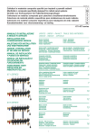
Contents:
Plumbing & Electrical Information
About the manifold
Page
2
First Fix Plumbing
Page
2
Second Fix Plumbing
Page
2
Generic Plumbing & Wiring Schematic
Page
3
First Fix Electrics
Page
4
Second Fix Electrics
Page
4
Wiring Centre Schematic
Page
5
Testing & Commissioning
Page
6
Balancing
Page
7
Room Thermostats
Page
8
Water Temperature
Page
8
Maintenance and Troubleshooting
Page
9
Floor coverings and Underfloor Heating
Page
10
User Information:
Contact Details
Manufacturers Instructions
AutoCAD
End Page
Page 1
About the manifold:
First Fix Plumbing:
Automatic
Air Eliminator
Top Flow Meters
#
Isolation Valves
PLEASE CONSULT YOUR PLUMBER FOR
THIS. (Manifold flow rates and pressure
drops are available on request to assist with
the sizing of flow and return pipe work.
Flow Manifold
Thermo Actuator
Pressure /
Temperature
Gauge
Return Manifold
For the plumbing first fix, run appropriately
sized pipe work to the left hand side of
each manifold position as shown on the
AutoCAD.
Usually an extra Flow pump is supplied.
This is sized to meet the needs of the
underfloor heating system. This should be
placed after the heat pump.
Male to female
Adapter
Drain / Fill
Point
Return Manifold
Connects to the return side of the heating
system.
Flow Manifold
Connects to the flow side of the heating
system.
Top Flow Meters
Show the flow rate of water for each group.
These can be adjusted to regulate the flow of
water through the individual pipe circuits to
balance the system as designed by Tailored
Heat
Auto air eliminators
Removes unwanted air form the system.
Fill/Drain points
Used when filling and testing. Also used for
maintenance.
Pressure/Temperature gauge
Shows the flow temperature and system
pressure.
Pump
Circulates water around the floor Heating
pipes.
Mixing Valve
Regulates the incoming flow temperature to the
floor heating system. Operating temperatures
of between 35-55 degrees centigrade.
Mixing Valve sensor
Senses the mixed water flow temperature.
Isolation Valves
These are used to isolate the underfloor
heating circuit for maintenance and are also
used when filling and testing the system.
Thermo Actuator
Opens and shuts the valve on each group. It is
controlled by the room stat in each controllable
area.
Subject to pipe sizing and routing, it may be
necessary to fit ‘local’ pumps to assist with the
performance of the system.
For incorporation into the whole plumbing
scheme a general schematic is shown
below. This may vary depending on your
clients needs.
Second Fix Plumbing:
Once fitted, the manifold will normally have
been pressurised for some time.
Check the pressure on the manifold.
Connect the flow and Return pipework to the 1”
isolation valves.
•
•
Note the isolation valves are fitted with a
union fitting. If this is loosened, please
retighten and re-pressurise the system.
The flow isolation valve is normally
coloured red and is located on the top
manifold chamber.
The return isolation valve is normally coloured
blue and is located on the bottom manifold
chamber.
Often an external hot water tank is
supplied with the heat pump system,
Detailed plumbing schematics should be
supplied by you heat pump manufacturer.
An Expansion vessel should be
included in the system; this should be
supplied by your heat pump supplier.
We can supply the water volume of the
UFH System on request.
Page 2
Generic Plumbing & Wiring:
Page 3
First Fix Wiring:
Second Fix Wiring:
Generally, each manifold is served via a
Wiring centre. The wiring centre should be
located in the immediate vicinity (within
600mm) of the manifold position shown on
the AutoCAD. The closest wiring centre is
then linked directly to the boiler.
Following the wiring centre diagram on the
next page, install each component to the
system. In summary:
Wiring Centres:
•
For the incorporation of other controls for
Hot Water and radiators, reference the
generic plumbing and wiring diagram on
page 3.
1. Power the whole central heating
system (ideally including the boiler)
from a 5A fused spur.
a. Run a two core and earth
2
cable (0.75mm ) to the closest
wiring centre position
b. Parallel off, if necessary, with
two core & earth cables to the
other wiring centre positions.
2. For the main pump enable, run a three
2
core cable (0.75mm ) to the main
pump position from the closest wiring
centre position.
a. Parallel off, if necessary, with
a two core cable to the other
wiring centre positions.
3. For the room thermostats, run 3 core
and earth cables from each thermostat
position as shown on the AutoCAD
back to the wiring centre position
serving that area.
4. For room thermostats in wet rooms,
locate the thermostat on the ‘dry’ side
of the wall and provide a sleeve to
inside the wet room. The Thermostat
is provided with a remote sensor,
which can be mounted in the floor or
on the wall.
5. Providing the wiring centre is located
within 600mm of the manifold position,
no first fix wiring is necessary for the
actuators supplied as they are
supplied with approximately 600mm of
cable ready attached,
•
•
•
•
Link the fused spur neutral to the Neutral
terminal on the closest wiring centre.
Link the fused spur live to the Live terminal
on the closest wiring centre.
Using one of the two core cables, link the
Live and Neutral terminals on the wiring
centre to the next wiring centre and repeat
as necessary.
Using the other two core cable, link the
primary pump Live to the ‘boiler enable’ ‘C’
terminal. Link the primary pump neutral to
the pump relay ‘N’ terminal, Link the pump
‘L’ to the boiler enable ‘NA’, Link the pump
earth to the mains earth .
For manifold pump sets, Link the wiring
centre pump relay ‘L’ to the pump live and
the pump relay ‘N’ to the pump neutral,
Link the pump earth to the earth.
Thermostats:
•
Link the screened cable into the wiring
centre matching the terminals on the
thermostat to the terminals on the wiring
centre.
Actuators:
•
•
Connect these into the bottom section of
the terminal block for each thermostat.
Take care to ensure the correct actuator is
fitted to the correct group on the manifold.
Page 4
Wiring Centre Schematic:
Page 5
Testing:
Commissioning:
The majority of the initial testing should be
undertaken by the electrician:
BS1264-4 recommends that the screed
should not be heated for at least 21 days.
1. Switch the Time Clock on
2. Switch on the first thermostat for the
first manifold.
3. Check the correct actuator is rising
and is mounted on the correct group
on the manifold.
4. Check the pump is running (you can
check the voltage or feel the vibration
on pump casing – if you change the
speed of the pump, you should feel
the speed change).
5. Check the boiler is running.
6. Repeat steps 2 & 3 for the rest of the
thermostats served by the first
manifold.
7. Switch off all the thermostats served
by the first manifold.
8. Repeat steps 2-7 for each manifold on
the system.
9. Finally set the Time clock to the clients
preferences and switch all the
thermostats on to their desired
temperature.
10. A check list has been supplied below
to assist.
However, BS8204-1 suggests that the
screed be left to dry out as slowly as
possible.
Item
Therefore, we would recommend the
system be commissioned at least two
months (and certainly no earlier than 21
days) after laying the floor screed.
1. Following electrical testing, set the
clock and room thermostats to operate
as you require.
2. Set the mixing valve water
0
temperature to 30 C .
3. Run the system at this temperature for
at least 3 days.
4. Slowly increase the water temperature
0
5 C every day until the maximum of
0
55 C is reached.
5. Run the system at this temperature for
a further 4 days.
6. Then reduce to the water temperature
to suit your requirements
OK
1. Thermostats programmed
correctly
2. Thermostats Operational
3. Stats located correctly
4. Manifold labelled correctly
5. Stats matched to actuators
correctly
6. UFH pump working
7. Boiler firing
8. Wiring centres linked
9. Correct Flow Rates
Page 6
Balancing the manifold:
In line with the design undertaken, along
with individual room controls, each group
of pipe has its own design flow rates.
The flow rates for this project are detailed
on the AutoCAD provided. You may wish
to summarise them on the table shown.
The “Top Flow Meter” consists of two
parts, one is a plastic lockshield, the other
is a variable valve inside the chamber to
calibrate the flow rate, and this can be
adjusted by turning the plastic nut at the
bottom of the flow metre sightglass.
To adjust the valves to the correct flow
rate, ensure the underfloor heating pump
is running and follow the instructions
below:
1. Ensure that all the thermal actuators
or manual control valves on the return
chamber of the manifold are fully open
and that the system is hot.
2. Lower all the Flow meter Lockshields
collars by pushing them downwards.
3. Open all Flowmeter/Lockshield valves
by turning them anticlockwise using
the lockshield collar.
4. Adjust the flow rates on the flow meter
by gripping the black hexagonal nut
and turning anticlockwise.
5. Start by setting the flow rates
approximately between 1.5 - 2.5 l/min
on all groups. Turn the flow meter
clockwise to reduce the flow rate, and
anticlockwise to increase the flow rate.
6. Now reduce the flow rate on the
groups that require lower flow rate.
7. Now increase the flow rate on the
groups that require a high flow rate.
8. Repeat steps 5 and 6 till the system is
balanced.
9. Once balanced – to prevent further
adjustments being made the flow
meter can be locked in place by lifting
the lockshield collar
10. Repeat the procedure for each
manifold.
11. For future reference you can note the
flow rates set on the tables opposite.
NOTE:
This work can be undertaken on
installation by our engineers on request.
Flow Rate Table:
CIRCUIT NAME
FLOW RATE
CIRCUIT NAME
FLOW RATE
CIRCUIT NAME
FLOW RATE
CIRCUIT NAME
FLOW RATE
1.
2.
3.
4.
5.
6.
7.
8.
9.
10.
11.
1.
2.
3.
4.
5.
6.
7.
8.
9.
10.
11.
1.
2.
3.
4.
5.
6.
7.
8.
9.
10.
11.
1.
2.
3.
4.
5.
6.
7.
8.
9.
10.
11.
Page 7
Room Thermostats:
Water Temperature Control:
Room temperature control is a vital and
integral part of the control and design of
any underfloor heating system.
General Principles:
Each room is generally unique in
design and has it’s own heat
performance characteristic.
Apart from the individual room controls
given by the room thermostats, Water
Temperature is another important
element of control for the Tailored Heat
System.
Therefore it is important that each room
has it’s own control.
The water temperature directly affects the
output of the system.
To manage this Room Thermostats are
used.
For example:
o
1. If the water temperature is 30 C in
winter then the rooms will not achieve
their designed temperature not matter
what the thermostat is set to.
2. Conversely, if the water temperature is
o
50 C in the summer then room may
get too warm and too quickly before
the thermostat switches it off.
It is important to understand the function
they perform:
o A room thermostat acts as a switch
only
o They can only switch the system on or
off.
o They cannot control how much heat
comes into the room from the heating
system (the water flow rate and
temperature affect heat input).
Typically all our room thermostats work off
a 12V and measure air temperature only
However, an external floor or air sensor
and be used if required. This sensor can
either be placed in the floor to control the
floor temperature or on the wall to
measure room temperature.
With underfloor heating systems,
accurately controlled water temperature
can improve both comfort levels and
efficiency.
The Water Temperature control is
managed by the Heat pump controls
Please consult the heatpump user manual
for details
When it comes to the placement of the
thermostats, they are best placed on
internal walls and not in direct sunlight.
We have recommended thermostat
positions on our AutoCAD design.
With your system, you have been supplied
with the room thermostats; we have
attached the manufacturers operating
instructions.
Page 8
Maintenance:
The underfloor heating system should not
require maintenance as such.
All pumps provided are self-regulating and
require no maintenance.
However, it is suggested that you:
1. Periodically (six monthly) check that
the compression fittings are tight (i.e.
the 27mm silver nut between manifold
and plastic underfloor heating pipe.)
Be careful doing this on the return
manifold as you will need to grip the
flow meter with a adjustable wrench to
stop it from moving.
2. Periodically check the pressure of the
system to ensure that there is water
present. We would normally expect to
see a pressure in the region between
1 – 2.0 bar.
If you are ever unsure that the system is
maintaining pressure, simply isolate the
manifold by turning the two red handles on
the isolation valves, noting the pressure
and leaving for approximately one hour.
When you return the pressure may have
dropped, as long as it has not dropped to
zero, then the system is holding pressure.
Troubleshooting:
Detailed over are some common problems
that may arise in the operation of the
system:
My rooms are not heating up!
Is the system switched on to occupied
mode?
o Check time clock settings.
Is the thermostat switched on and calling
for heat?
• You can check the thermostat by
turning the temperature dial; you
should hear it click off as you turn it
down or on if you turn it up.
Is the actuator rising up?
• You can see the buttons with a blue
collar is they are fully up, no collar if
they are down.
Is the correct thermostat connected to the
correct actuator?
• By turning the thermostat on and off
you should see the correct actuator
button rising and falling – it takes
several minutes for a button to rise
and then to fall.
Is there a hot water flow to the manifold
and is it being passed through the
manifold?
• Check the temperature gauge on the
manifold.
• Do both manifolds feel warm or hot?
• Are both isolation handles open
(pointing in line with the pipes)?
Is the pump running?
• You can usually feel a slight vibration
on the pump when it is running (If you
change the speed of the pump, you
can feel the speed change).
For testing electrical wiring &
components we would recommend
that suitably qualified engineer is
contacted.
The pressure shown is too low!
•
•
•
Most systems will lose pressure over
time.
You can top up the pressure from the
mains supply to the boiler. This should
improve the pressure of the whole
system.
If you think there is an issue with the
manifold, isolate the manifold by
turning the two red handles on the
isolation valves, noting the pressure
and leaving for approximately one
hour. When you return the pressure
may have dropped, as long as it has
not dropped to zero, then the system
is holding pressure.
Page 9
Floor coverings:
time to warm up and cool down the
floor.
When laying the stone use a
continuous adhesive bed to ensure
continuity between the screed and the
stone.
In all cases, we would recommend you
check and follow the installation procedure
given by the floor covering manufacturer
and installer.
•
In all cases moisture and movement is a
big issue to monitor:
NOTE: For thick stone areas in excess of
2
40m , a movement joint should be
considered. This should pass through the
stone and approximately 1/3 into the depth
of the screed.
•
•
•
To limit the effects of moisture, ensure
the screed is as dry as practicable.
BS1264-1 suggests the screed will dry at
a rate of one day per mm of the first
50mm, followed by an increasing time for
each mm above this thickness.
After the two month period and before
any floor coverings are laid, we would
recommend the system is heated and
cooled several times to drive of moisture.
(As the screed cools moisture is ‘sucked’
into the dry areas, as the screed is
warmed, the top layer is dried out.)
SEE PAGE 6
Normally, when laying the floor covering,
the common recommendation is that the
underfloor heating system is switched off
approximately 48 hours before the
covering is laid and left for 48 hours after
laying before switching the system back
on.
Detailed below are some basic
guidelines to assist when choosing
your final coverings:
Vinyl:
When using this floor covering, please
ensure that suitable glue is used when
laying and fixing this in position.
PLEASE NOTE THAT THE FLOOR
SURFACE TEMPERATURE CAN BE UP
TO 33 DEG C.
Hardwood:
This floor covering is also compatible with
underfloor heating although some
consideration has to made with the
heating design:
1. The designer will limit the temperature
of the floor so that it does not damage
the wood or glues used with it.
2. Do not lay hardwood that is thicker
than 22mm.
3. Do not lay felt underlay underneath
the flooring as this is a very good
insulator.
Movement is a big factor with hardwood.
The manufacturers seem to recommend
that a narrow board with low moisture
contents is used.
When installing the hardwood, there are
many different methods – consult your
supplier for their recommended method.
Carpets:
When considering carpets, the Underfloor
Heating Manufacturers association
recommends that the combined TOG
rating of the Carpet and Underlay does not
exceed 1.5 TOGs.
Tile or Stone:
Some general guidelines that may help
are:
This floor covering is the most compatible
with underfloor heating as it transmits the
heat very well.
•
•
•
•
When tiling, use a good quality tile
adhesive as this is normally flexible
and can take a small amount of
movement by the screed.
Stone can be laid at any thickness.
The only issue this raises is that the
thicker the stone, the larger the
thermal mass and slower the reaction
•
•
•
•
Do not use felt underlay
Use a modern underlay such as the
‘Gates Technics 5’ product.
Do not use pure wool carpets as their
structure traps air and insulates, use
an 80/20 blended one.
Do not use a felt backed carpet – use
a woven backed one.
Go for a dense pile carpet as this is
less likely to trap air.
The thinner the carpet the better it
performs with underfloor heating.
Page 10