1
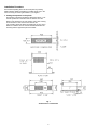
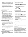
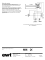
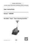
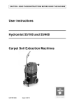
Installation and
Operating Instructions
Hydronic Base Unit Heater model EWBU20
Important Safety Advice
READ THESE INSTRUCTIONS BEFORE USE
• If the appliance is damaged, check immediately with the
supplier before installation and operation.
• Leave the appliance disconnected from the voltage supply
until it is commissioned.
• DO NOT USE THIS HEATER IN THE IMMEDIATE
SURROUNDINGS OF A BATH, A SHOWER OR A
SWIMMING POOL.
• THIS HEATER MUST NOT BE LOCATED IMMEDIATELY
BELOW A FIXED SOCKET OUTLET OR CONNECTION
BOX.
• DO NOT COVER or obstruct in any way the heat outlet
grille located at the front of the heater. Overheating will
result if the heater is accidentally covered.
• If young children, the aged or infirm are likely to be left in
the vicinity of the heater, we advise that adequate
precautions should be taken to ensure that contact with the
heater is avoided and objects cannot be inserted into the
product.
• Do not use this heater in areas where excessive dust
exists.
• Do not touch or obstruct the grille area when the heater is
operating.
Introduction
This heater has been designed for fitting in the space behind the
plinth of floor standing kitchen units or other fitted furniture units. It
is recommended that the heater is not installed under cupboards
used for storing perishable goods. It can be accommodated in
plinths with a minimum height of 120 mm, and is suitable for
cupboards of 475 mm width and above.
This heater may be fitted in place of or in addition to existing
radiators. Using the hot water from the central heating system and
a powerful electric fan it will produce an average 2.0 kW of heat
into the room.
The heat output may be increased or decreased by selecting either
the boost speed switch or the normal speed switch located under
the Winter / Summer switch.
Installation instructions
The heater is more easily fitted during the installation of new
furniture units, or on existing furniture units if they can be
temporarily moved from their position against the wall. If an
existing furniture unit cannot be moved, then it may be necessary
to remove the back of the unit in order to gain access to carry out
the wiring installation.
Before installing the unit consider the location with respect to the
following:
• The electrical supply and cable length
• Position of system pipework and flexible hose length.
• Position the heater to deliver heat effectively without causing
personal discomfort from overheating while standing at work
surfaces etc.
• Minimum plinth height of 120 mm and minimum furniture width
of 475 mm.
Central heating system design
1. When fitting the appliance onto a central heating system check
that the boiler is capable of delivering extra heat into the
appliance by resizing the system. The appliance will add an
average of 2 kW (6,830 Btu/Hr) onto the boiler sizing.
2. Due to the low water content of the heat exchanger in the
appliance compared to a panel radiator in the system, an
adequate flow of water should be maintained to compensate for
rapid cooling of the water as it passes through the exchanger
i.e. maximum efficiency is gained if the appliance is placed as
near to the central heating pump as possible to give the
maximum pressure head across the appliance.
IMPORTANT — READ CAREFULLY AND RETAIN FOR FUTURE REFERENCE
Installation Procedure
Ensure that all packing items are removed (read any warning
labels carefully). Retain all packing for possible future use, in the
event of moving or returning the heater to your supplier.
1. Cutting the aperture in the plinth
Cut aperture in furniture unit plinth to dimensions shown. This
must be positioned so that the minimum distance from the
bottom of the aperture to the TOP surface of any floor covering
is not less than 12 mm and not more than 25 mm.
If an overhang above the heater is greater than 75 mm, then a
distance of at least 100 mm must be maintained between the
overhang and the uppermost part of the heater.
Fig. 1
All dimensions in millimetres
2
2. Water connections
Operation
WARNING: Do not connect to electricity supply when making
water connections.
Connect the flexible pipes to the system flow and return pipes.
The appliance terminates in 15 mm pipe tails (top pipe flow –
bottom pipe return). Connect the valve ends of the flexible pipe
to the rear of the appliance. (Note: The direction of flow arrows
on the valves are not significant in this application.)
Fill and vent the system and bleed the air out of the heat
exchanger using the bleed screw provided (located at the top of
the flow pipe)
Close the vent and check the appliance for water leaks. If any
water escapes from the bleed screw ensure that it does not fall
onto any electrical wiring or connections. After bleeding the
appliance ensure that electrical controls are completely dry
before connecting to the power supply.
1. Switch on the electricity supply to the heater.
2. Winter Use – for heating
Set the Winter / Summer switch to
(Winter position).
or boost
fan speed on the changeover
Select either low
switch depending on heat required.
Winter/summer switch
Boost/Low speed switch
Fig. 2
3. Power supply connection
3. Turn ON the central heating system.
4. As hot water reaches the heat exchanger the low limit
thermostat should cut in and the fan will start to operate (set at
38oC)
5. Summer use – cool blow
The hydronic base unit heater may be used in Summer to
provide air circulation without heat.
Set the Winter / Summer switch to
(Summer position), and
choose between low
or boost
fan speed.
WARNING: THIS APPLIANCE MUST BE EARTHED.
This heater must be used on an AC~ supply only and the
voltage marked on the heater must correspond with the supply
voltage.
The installation of this appliance should be carried out by a
suitably qualified individual and be in accordance with the
current IEE wiring regulations.
Before undertaking installation work, ensure the electricity
supply is disconnected from any relevant fixed wiring.
The appliance is fitted with 2 metres of flexible cable
3 x 0.75 mm2 for electrical connection. The cable may be used
to connect the heater to the fixed wiring of the premises through
a suitable connection box. The supply circuit to the heater must
incorporate a double pole isolating switch having a contact
separation of at least 3 mm. The power supply cable should be
routed through the plinth space to the connection box, ensuring
that the cable is left with enough slack to allow removal of the
appliance for maintenance. The cable must be protected form
any sharp edges.
In this position the fan will run at the selected speed until
manually reset.
Insufficient heat output from heat exchanger may be caused by:
• Airlock in the heat exchanger – (ISOLATE FROM
ELECTRICAL SUPPLY)
Remove grille and bleed the appliance as in the ‘Water
Connections’ instructions (above)
• Hot water temperature too low – the boiler thermostat may
need increasing.
• Bulk of the water circulating through the radiators – rebalance
by closing back lockshields valves on radiators to increase
water flow through the appliance.
• Dirty heat exchanger.
4. Fitting the rear support bracket
The heater is supplied with a rear support bracket. Fit to the
back of the appliance with the two black screws supplied.
Adjust the rear support bracket so that the vertical distance
from the underside of the appliance to bottom of rear support
bracket equals the vertical distance from the floor in the
cupboard space to the bottom of the aperture opening. The
slots in the rear support bracket allow it to be adjusted to the
required height.
Cleaning and User Maintenance
WARNING: DISCONNECT POWER SUPPLY before carrying
out any maintenance.
General cleaning
5. Marking the fixing positions
External appearance can be maintained by wiping occasionally
with a damp cloth; for stain removal, a weak soap solution can be
applied, then wipe dry.
Slide the heater into position in the plinth aperture with the front
edge just behind the line of the plinth..
Note: Ensure that the flexible pipes are not kinked and that the
electrical cord is not in contact with hot surfaces.
Replace the plinth and bring the appliance forward so that the
front edge slightly projects through the plinth.
Position the grille in front of the heater and fix with two screws
(smaller screws).
Mark the eight fixing holes (two on each side, two on the top
and two on the bottom). Remove the grille and drill 2 mm pilot
holes
Internal cleaning and maintenance
From time to time it may be necessary to remove the heater from
the furniture unit so that the interior of the heater and the heater
compartment can be cleared of any accumulated dust or fluff.
To remove, unscrew the eight fixing screws and withdraw the
appliance from the plinth. Remove the top cover and gently
remove dust with a soft brush and vacuum cleaner, taking care not
to damage the fan or heat exchanger.
Do not tamper with any electrical parts.
Remount the heater in the plinth ensuring the rear support bracket
is still adjusted correctly, the flexible pipes are not kinked and the
mains cable is not touching any hot or sharp surfaces.
6. Mounting the heater into the plinth
Make sure that the heater is adequately supported and that the
air inlet slots are not obstructed. Fix the grille to the heater and
use the eight longer screws provided to secure the heater to
the plinth.
3
After sales service
Your Hydronic Base Unit Heater is guaranteed for one
year from date of purchase. We undertake to repair or exchange
free of charge within this period, any part found to be defective
due to a manufacturing fault.
Should you require after sales service, please get in touch with the
supplier through whom you purchased the appliance, or the contact
our customer services department on the number listed below.
Please do not initially return a faulty appliance or part of an
appliance to us as this may result in transit damage and/or delay
in providing service. Let us know your difficulty quoting the model
number and series letter of the appliance. We will then take the
appropriate action.
The electricity supply to the heater can now be switched back on.
Fig. 3 – Wiring Diagram
Specification subject to change without prior
notice.
Glen Dimplex UK Limited
Millbrook House
Hedge End, Southampton
SO15 0AW
Customer Helpline
Tel:
0870 727 0101
Fax:
0870 727 0102
Republic of Ireland: 01 842 4833
4
0219/09/A
8/18642/0