1
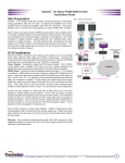
LA3000 Series
Logic Controls All-in-One
POS Touch Terminal
USER MANUAL
-i-
NOTICE
The manufacturer of the Industrial Computer makes no representations or warranties, either
expressed or implied, by or with respect to anything in this manual, and shall not be liable for
any implied warranties of fitness for a particular purpose or for any indirect, special or
consequential damages. Information in this document is subject to change without notice and
does not represent a commitment on the part of the manufacturer.
FCC NOTICE
This device complies with Part 15 of FCC Rules. Operations are subject to the following two
conditions: (1) this device may not cause harmful interference, and (2) this device must accept
any interference received, including interference that may cause undesired operation.
LOGIC CONTROLS, INC.
355 Denton Ave
New Hyde Park, NY 11040
TEL: (516) 248-0400
FAX: (516) 248-0443
Email: [email protected]
http://www.logiccontrols.com
- ii -
TABLE OF CONTENTS
OVERVIEW ......................................................................................................... 1
SAFETY INSTRUCTIONS................................................................................... 2
CARE AND HANDLING...................................................................................... 3
PRODUCT FEATURES ...................................................................................... 4
HARDWARE INSTALLATION ............................................................................ 5
SOFTWARE INSTALLATION............................................................................. 6
TOUCH MONITOR ADJUSTMENTS .................................................................. 8
TROUBLESHOOTING ...................................................................................... 12
TECHNICAL SPECIFICATIONS....................................................................... 13
- iii -
OVERVIEW
The Logic Controls LA3000 integrated POS system are fanless units fit for retail or hospitality
environments where dust or grease may be present or when fan noise is not desirable. The LA3000 allin-one touch terminal combines the reliable performance of touch technology with the latest advances in
LCD display design for a natural flow of information between user and the all-in-one touch terminal.
The LCD monitor incorporates 15” color active matrix thin-film-transistor (TFT) liquid crystal display to
provide superior display performance. A maximum resolution of XGA 1024x768 is ideal for displaying
graphics and images. Other outstanding designs that enhance this LCD monitor’s performance are Plug
& Play compatibility, and OSD (On Screen Display) controls. The touch screen is from the industry’s
leader Elo Touch Systems with proven reliability and supreme performance.
The optional Line Display and Magnetic Stripe Reader add-on modules complete the system as a fully
integrated POS terminal.
-1-
SAFETY INSTRUCTIONS
Follow all warnings, precautions and maintenance as recommended below to maximize the life of your
unit. This manual contains information that is important for the proper setup and maintenance of the all-inone touch terminal. Before setting up and powering on the all-in-one touch terminal, read through this
manual, especially sections on installation and operation.
1. We recommend all servicing done on this product be done by qualified service personnel. Please refer
all other servicing to the Logic Controls RMA Dept or a repair provider that has been certified by Logic
Controls.
2. To avoid risk of electric shock, do not disassemble the power supply adapter or display unit cabinet.
The unit is not user serviceable.
3. Unplug this product from the wall outlet before cleaning. Use only mild cleaning agents and do not
immerse in water.
4. Do not use this product near water. It is important that the all-in-one touch terminal remains dry. Do
not pour liquid into or onto the all-in-one touch terminal. If the all-in-one touch terminal becomes wet,
unplug from the wall outlet and do not attempt to repair it yourself.
5. The all-in-one touch terminal power adapter is equipped with a 3-wire, grounding power cord. The
power cord plug will only fit into a grounded outlet. Do not attempt to fit the plug into an outlet that has
not been configured for this purpose. Do not use a damaged power cord. Use only the power cord that
comes with the unit. Use of an unauthorized power cord may invalidate warranty.
6. Do not allow anything to rest on the power cord. Do not locate this product where persons will walk on
the cord.
7. If an extension cord is used with this product, make sure that the total ampere rating of the equipment
plugged into the extension cord does not exceed the extension cord ampere rating. Also, make sure
that the total rating of all products plugged into the wall outlet does not exceed the fuse rating.
8. The slots located on the sides and top of the all-in-one touch terminal case are for ventilation. Do not
block or insert anything inside the ventilation slots.
9. Unplug this product from the wall outlet and refer servicing to qualified service personnel under the
following conditions:
•
When the power cord or plug is damaged or frayed
•
If liquid has been spilled into the product
•
If the product has been exposed to rain or water
•
If the product does not operate normally when the operating instructions are followed. Adjust only
those controls that are covered by the operating instructions since improper adjustment of other
controls may result in damage and will often require extensive work by a qualified technician to
restore the product to normal condition.
•
If the product has been dropped or the cabinet has been damaged
•
If the product exhibits a distinct change in performance, indicating a need for service.
-2-
CARE AND HANDLING
The following tips will help keep your all-in-one touch terminal functioning at the optimal level.
•
Remember to unplug the display unit from the power outlet before cleaning.
•
Do not use alcohol (methyl, ethyl or isopropyl) or any strong dissolvent. Do not use thinner or
benzene, abrasive cleaners or compressed air.
•
To clean the display unit cabinet, use a cloth lightly dampened with a mild detergent. Do not
immerse unit in water.
•
Avoid getting liquids inside your all-in-one touch terminal. If liquid does get inside, have a
qualified service technician check it before you power it on again.
•
Do not wipe the screen with a cloth or sponge that could scratch the surface.
•
To clean the touchscreen, use window or glass cleaner. Put the cleaner on the rag and wipe the
touchscreen. Never apply the cleaner directly on the touchscreen.
-3-
PRODUCT FEATURES
POS System Features
•
Small foot print
•
Designed for ease-of-service
•
Rugged and stable construction
•
Stylish design
•
Optional integrated stream line Magnetic Stripe Reader with USB interface.
•
Optional integrated vacuum fluorescent display featuring two line by 20 character with 9.5mm
character height, adjustable viewing angle and USB interface.
•
Detachable stand for wall-mounting application.
•
Optionally supports dual LCD displays
•
Detachable CPU base unit (patent pending)
Touch Monitor Features
•
15” XGA TFT color display support resolution up to XGA 1024x768. Compatible with VGA,
SVGA, XGA (non-interlaced).
•
5-wire resistive touch panel
•
High contrast with 400:1 ratio
•
Anti-scratch and anti-glare coatings on screen surface
•
Advanced OSD control for picture quality adjustment.
•
Built-in speakers
Computer Features
•
Fanless
•
Single board computer limits number of internal cables
•
Intel Celeron-M ULV CPU 800 MHz to 1.1 GHz
•
Supports RAM size from 128MB to 1GB
•
Large compliment of available I/O ports: 4 USB 2.0, 4 RS232, 2 independent SVGA, Ethernet,
Parallel, PS/2 Keyboards/Mouse, Audio Input/Output
•
Mass storage choices: HDD, CF, or both HDD and CF
•
No moving parts with compact flash mass storage
•
System boot from HDD, CF, USB, or network
•
Multimedia ready: MPEG-2 decoding and video, Integrated 128-bit 2D and 64-bit 3D graphics
engine, AC97 Audio CODEC
-4-
HARDWARE INSTALLATION
The LA3000 is shipped with cables already installed in the all-in-one touch terminal and connected
properly. It only need to connect the power cord, network cable, and other external peripheral devices
such as receipt printer or bar code scanner. In case re-installation of the cables is required, follow the
steps below.
If the all-in-one touch terminal has integrated line display option, the line display USB driver has to be preinstalled before making connections. Refer to Software Driver section for details.
Before connecting cables to the all-in-one touch terminal and computer, be sure that power of the
computer and all-in-one touch terminal are turned off. Power switch of all-in-one touch terminal is located
on the front of the monitor stand.
1.
Remove 2 screws from the front of the monitor stand and pull back the stand back cover to open.
2.
Thread the VGA video cable, audio cable, USB cable, and DC power cord through the oval hole at
the front of the monitor stand.
3.
Connect the video cable to touch monitor VGA connector. Tighten by turning the two thumb screws
clockwise to ensure proper grounding.
4.
Connect the USB cable to the touch monitor USB input.
5.
Plug the audio cable into the audio jack of the touch monitor.
6.
Plug the DC power cable into the DC power jack of the touch monitor.
7.
Thread all cables through opening at base plate of stand so that all cables go into the computer
metal base case.
8.
Thread the DC power cable of the power adapter through the opening at the base from the bottom
and plug into the power socket at the back of the metal base case. Close the back cover.
9.
Secure the back cover with the 2 screws from the front.
10. Connect VGA cable, audio cable and USB cable to the corresponding connectors on the computer
board.
11. Connect one end of the power cord to the all-in-one touch terminal power adapter and the other end
to the power outlet.
12. Press the power switch on the front of monitor stand to turn on the power.
-5-
SOFTWARE INSTALLATION
Drivers for the touch monitor and line display are preinstalled. To reinstall those drivers, install
application software, or install drivers for new peripherals, an external USB CDROM can be connected to
the computer base USB port. Alternatively, USB flash drive or network drive can also be used depending
on installation software requirement.
Installing Touch Monitor Driver
Logic Controls provides driver software that allows the touch monitor to work with the computer. Drivers
are located on the enclosed CD-ROM for the following operating systems:
• Windows XP
• Windows 2000
1.
Insert the CD-ROM in your computer’s CD-ROM drive.
2.
Double click Setup.EXE within the Windows folder.
3.
Click Next
4.
Click Yes to accept the License Agreement
5.
Click Next to select the default destination folder or click Browse to install in an alternate location.
6.
Select the components you want to install (USB or RS232 or both).
7.
Click Next to Select the default Program folder Logic Touch.
8.
Select Next to continue installation.
Installing USB Line Display Driver
The USB drivers are available for download on our web site at www.logiccontrols.com. Please download
and unzip the suitable driver files before installation. There are two types of drivers available. If the POS
software is only able to access COM ports for the pole display, use the Virtual COM port device driver.
Second one use a specific device name (\\.\LCLD9) to access the pole display directly. Install this driver
if you are using OPOS or the POS software was tailored to use this device name.
1.
DO NOT plug the device in USB port.
2.
Run “setup.exe” program in this driver package.
3.
Select "Device Name Driver" or "Virtual COM Port Driver" by clicking the radio buttons.
4.
Click <Install> button to start pre-installation and click <OK> to end setup program.
5.
Plug the device in USB port and wait for the hardware wizard message box to display.
6.
Click <Next> button, and then click <Continue Anyway> button to continue installation automatically.
When finished, click <Finish> button to end installation.
7.
Invoke Device Manager to check the device driver's name or COM port number. Device Name driver
is installed under "Universal Serial Bus Controllers" and Virtual COM Port Driver is installed under
"Ports (COM & LPT)".
Installing USB Magnetic Stripe Reader Driver
The integrated MSR does not need USB driver installation. It will use the standard HID keyboard driver
and card data input from the MSR unit will be presented to Windows as normal keyboard input.
-6-
Programming the Magnetic Stripe Reader
The integrated MSR is programmable to meet specific requirements of different software. The default
output format of the MSR is set to a common protocol that is compatible with most software.
Programming of the MSR may not be necessary. Before editing the MSR parameters, please refer to the
user manual of the Point-of-Sale software or credit card verification software to find out what are the
requirements on the output format.
To install the programming utility, run the "Setup" program in the utility package. Select destination folder
and click "START" to start the installation process. Skip any warning message dialog boxes by clicking
"Yes" or "Continue". When installation is completed, reboot the computer. The utility program file
MREdit.exe will be copied to the harddisk in the installation target folder (default is C:\Program Files\Logic
Controls).
To program the MSR for specific output format, follow the procedure below:
1. Start the Programming Utility by double clicking on the "MREdit.exe" icon in the folder where the utility
is installed.
2. A new parameter template can be prepared on the screen by editing the parameters to be used.
Alternatively, an old template can be brought into the utility for editing. Either OPEN from a .MTL file or
READ from the magnetic stripe reader. To open an old .MTL file, click on [File] --> [Open] on the Menu
bar or click on the "File Open" icon on the toolbar. To read from the MSR, click [Access MR] --> [Read
from MR] on the Menu bar or click on the "Read from MR" icon on the toolbar.
4. After editing the parameters, it is advised that the template should be first saved into a .MTL template
file for future reference and for programming multiple number of magnetic stripe readers. Then, click
[Access MR] --> [Write into MR] on the Menu bar or click on the “Write to MR” icon on the toolbar to
write the template into the magnetic stripe reader.
5. To test the programmed magnetic stripe reader output, open HyperTerminal and swipe a magnetic
stripe card across the reader. The output will appear in HyperTerminal screen. Check that the output
format is correct as programmed.
-7-
TOUCH MONITOR ADJUSTMENTS
The all-in-one touch terminal usually does not require adjustment. Variations in video output and
application may require adjustments to your all-in-one touch terminal to optimize the quality of the display.
For best performance, the monitor display should be operating in native resolution, that is 1,024x768 at
refresh rate of 60Hz to 75 Hz. Display resolution in Windows can be selected in the Settings tab of
Display Properties.
All adjustments made to the controls are automatically memorized. This feature saves you from having to
reset your choices every time you unplug the monitor or turn the all-in-one touch terminal power off and
on. Even if there is a power failure, the all-in-one touch terminal settings will not be lost.
Display Control Buttons
MENU
◄
Control Button
►
SEL
Function
1.
MENU
2.
◄
a. Enter contrast adjustment.
b. Move to next item clockwise.
c. Increase value of the parameter selected for adjustment.
3.
►
a. Enter brightness adjustment.
b. Move to next item counter-clockwise.
c. Decrease value of the parameter selected for adjustment.
4.
SEL
5.
Display or exit OSD menu.
a.
b.
c.
d.
Activate auto-adjustment.
Selects item on OSD menu for adjustment.
Confirms current parameter adjustment and exit to higher level menu.
Selects sub-menu.
Turns monitor display power on or off.
OSD Menu Functions
To Display and Select the OSD Functions:
1.
Press the Menu key to activate the OSD menu.
2.
Use ◄ or ► to move counter-clockwise or clockwise through the menu.
3.
Press the SEL key to select the highlighted parameter for adjustment. When selected, display
color of item will change from blue to black.
4.
Use ◄ or ► to increase or decrease value of the item being adjusted. Press SEL key to end
adjustment of the item.
5.
To quit the OSD screen at any time during the operation, press the Menu key. If no keys are
pressed for a period of time (default 45 seconds), the OSD automatically disappears.
-8-
OSD Control Options
Control
Description
BRIGHTNESS
Increases or decreases brightness.
CONTRAST
Increases or decreases contrast.
V-POSITION
Sets vertical position of display area. When the ◄ button is pressed, the
screen will move up. When the ► button is pressed, the screen will move
down.
H-POSITION
Sets horizontal position of display area. Moves the screen left or right. When
the ◄ button is pressed, the screen will move to the right. When the ► button
is pressed, the screen will move to the left.
RECALL DEFAULTS Returns display monitor parameters to factory default settings.
RGB
Select color temperature option from 9300, 6500, 5500, 7500 and USER.
Select USER option to make custom adjustments to the R/G/B values.
OSD EXIT
Exit OSD menu.
SHARPNESS
Adjust sharpness of display.
PHASE
Increases or decreases snow noise of the image if necessary after auto
adjustment.
CLOCK
Fine adjust dot clock if necessary after auto adjustment.
OSD H-POSITION
Moves OSD menu position horizontally on the screen. When the ◄ button is
pressed, the OSD menu will move to the right. When the ► button is pressed,
the OSD menu will move to the left.
OSD V-POSITION
Moves OSD menu position vertically on the screen. When the ◄ button is
pressed, the OSD menu will move up. When the ► button is pressed, the
OSD menu will move down.
OSD TIME
Sets duration (in seconds) the OSD menu will wait before closing
automatically after no button has been pressed.
AUTO ADJUST
Select this function to adjust V-Position, H-Position, Clock and Phase
automatically for the video input signal.
OSD LANGUAGE
Select OSD display language from English (ENG), French (FRA), German
(DEU), Spanish (ESP) and Japanese (JPN),
INFORMATION
Display information on current screen resolution, Horizontal Frequency (FH)
and Vertical Frequency.(FV).
-9-
Monitor Preset Modes
To reduce the need for adjustment for different modes, the monitor has default setting modes that are
most commonly used as given in the table below. If any of these display modes are detected, the monitor
automatically adjusts the picture size and centering. When none of the mode is matched, the user can
store their preferred modes in the user modes. The monitor is capable of memorizing up to 7 user modes.
The condition to store as a user mode is the new display information must have at least 1 KHz difference
for horizontal frequency or 1 Hz for vertical frequency or the sync signal polarities are different from the
default modes.
H. Freq. Band Width
Sync Polarity
Mode
Resolution
(KHz)
(MHz)
H
V
1
2
3
4
5
6
7
8
9
10
11
12
13
14
15
VGA 720x350 70 Hz
VGA 720x400 70Hz
VGA 640x480 60Hz
MAC 640x480 66 Hz
VESA 640x480 72Hz
VESA 640x480 75Hz
VESA 800x600 56Hz
VESA 800x600 60 Hz
VESA 800x600 75 Hz
VESA 800x600 72Hz
MAC 832x624 75 Hz
VESA 1024x768 60Hz
SUN 1024x768 65Hz
VESA 1024x768 70Hz
VESA 1024x768 75Hz
31.47
31.47
31.47
35.00
37.86
37.50
35.16
37.88
46.88
48.08
49.72
48.36
52.45
56.48
60.02
28.322
28.322
25.175
32.24
31.5
31.5
36
40
49.5
50
57.283
65
70.49
75
78.75
+
+
+
+
+
+
+
+
+
+
Native Resolution
The native resolution of a monitor is the resolution level at which the LCD panel is designed to perform
best. It is the actual number of pixels horizontally in the LCD by the number of pixels vertically in the LCD.
For the LA3000 LCD all-in-one touch terminal, the native resolution is 1024 x 768 (XGA). In almost all
cases, screen images look best when viewed at their native resolution. You can lower the video input
signal resolution setting of a monitor but not increase it.
When the input pixels contained in the video input format match the native resolution of the panel, there is
a one to one correspondence of mapping of input video pixels to LCD pixels. When the input video is at a
lower resolution than the native resolution of the LCD, the direct correspondence between the video
pixels and the LCD pixels is lost. The LCD controller can compute the correspondence between video
pixels and LCD pixels using algorithms contained on its controller. The accuracy of the algorithms
determines the fidelity of conversion of video pixels to LCD pixels. Poor fidelity conversion can result in
artifacts in the LCD displayed image such as varying width characters.
Display Angle
For viewing clarity and comfort, the all-in-one touch terminal can be tilted forward (up to 80° position) or
backward (down to 0° position).
CAUTION: In order to protect the all-in-one touch terminal, be sure to hold the base when adjusting the
angle, and take care not to press hard on the screen.
- 10 -
Monitor Power Management
The monitor is equipped with the power management function which automatically enters sleep mode to
reduce the power consumption when not in use. We recommend switching the monitor off when it is not
in use for a long time.
Power Mode
On
Sleep
Off
Consumption
<30W
<4W
<2W
NOTE: The monitor automatically goes through the Power Management System (PMS) steps when it is
idle. To re-activate the monitor from PMS condition, press any key on the keyboard or move
mouse.
- 11 -
TROUBLESHOOTING
There are no user serviceable components inside the LA3000. Service should be performed only by
Logic Controls or qualified personnel certified by Logic Controls. The following guide lines will help in
identifying the source of a problem.
Problem
Suggestions
The monitor does not respond
after you turn on the system
Check that the monitor’s Power Switch is on.
Turn off the power and check the monitor’s power cord and signal
cable for proper connection.
Characters on the screen are dim
Refer to the About Touchmonitor Adjustments section to adjust
the brightness.
The screen is blank
During operation, the monitor screen may automatically turn off as
a result of the Power Saving feature. Press any key to see if the
screen reappears.
Refer to the About Touchmonitor Adjustments section to adjust
the brightness.
Screen flashes when initialized
Turn the monitor off then turn it on again.
“Out of Range” display
Check to see if the resolution of your computer is higher than that
of the LCD display.
Reconfigure the resolution of your computer to make it less than
or equal to 1024x768. See Appendix A for more information on
resolution.
Touch doesn’t work
Make sure the USB cable is securely attached.
- 12 -
TECHNICAL SPECIFICATIONS
GENERAL
Power Adapter
Input AC 100-240V, 50-60Hz
Operating Conditions
Temperature 0°C to 40°C (32°F to 104°F)
Humidity
20% to 80% (No Condensation)
Altitude
up to 12,000 Feet
Storage Conditions
Temperature -20°C to 60°C (-4°F to 140°F)
Humidity
10% to 90% (No Condensation)
Dimensions
Overall height 13.5”, monitor vertical
13”, monitor 45 degree
9.4”, monitor horizontal
Monitor width 14.25” without MSR, 15” with MSR
Base width
8.25”
Base depth
11.6”
Weight (Net)
16.9lb
Certifications
UL, C-UL, FCC-B, CE, TUV, VCCI, C-Tick, MPRII
TOUCH MONITOR
LCD Display
15” TFT Active Matrix Panel
Display Size
304.(H) x228.(V) mm
Pixel Pitch
0.297(H) x 0.297(V) mm
Display Mode
VGA 640 x 350 (70Hz)
VGA 720 x 400 (70Hz)
VGA 640 x 480 (60 / 72/ 75Hz)
SVGA 800 x 600 (56 / 60 / 72/ 75Hz)
XGA 1024 x 768 (60 / 70 / 75Hz)
Max. Resolution
XGA (1024 x 768) at 75Hz maximum
Contrast Ratio
400 : 1 (typical)
Brightness
5-wire Resistive: typical 205 Cd/m2; Min 164 Cd/m2
Acoustic: typical 230 Cd/m2; Min 184 Cd/m2
Capacitive: typical 205/m2; Min 164 Cd/m2
Response Time
Tr: 5 ms, Tf: 12 ms (typical.)
Display Color
16.2M
Viewing Angle
Vertical -60° to +40°
Horizontal -60° to +60°
Input Signal
Video
Sync
R.G.B. Analog 0.7Vp-p, 75 ohm
TTL Positive or Negative
Signal Connector
Mini D-Sub 15 pin
Control Buttons
Menu, ◄, ►, Select, Power
OSD Menu
Contrast, Brightness, V-Position, H-Position, Recall Default,
Color Temperature, Sharpness, Phase, Clock, OSD Position,
- 13 -
OSD Time, OSD Language
OSD Languages
English, French, German, Spanish and Japanese
Plug & Play
DDC1/2B
Touch Panel (optional)
5-wire Resistive / Acoustic / Capacitive
Built-in Speakers
8 ohm 2W x 2
5-wire Touch
Positional Accuracy
Standard deviation of error is less than 0.080 in. (2.03 mm). This equates
to less than ±1%.
Touchpoint Density
More than 100,000 touchpoints/in2 (15,500 touchpoints/cm2).
Touch Activation Force
Typically less than 4 ounces (113 grams).
Surface Durability
Meets Taber Abrasion Test (ASTM D1044), CS-1OF wheel, 500g. Meets
pencil hardness 3H.
Expected Life
Has been operationally tested to greater than 35 million touches in one
location without failure, using a stylus similar to a finger.
Optical
Light Transmission
(per ASTM D1003)
Typically 85% at 550-nm wavelength (visible light spectrum).
Visual Resolution
All measurements made using USAF 1951 Resolution Chap, under 30 X
magnification, with test unit located approximately 1.5 in. (38 mm) from
surface of resolution chart.
Antiglare surface: 6:1 minimum.
Haze (per ASTM D1003)
Antiglare surface: Less than 15%.
Gloss (per ASTM 02457) Antiglare surface: 90 + 20 gloss units tested on a hard-coated front
surface.
LINE DISPLAY
Digits per Row
20
Number of Rows
2
Digit Configuration
5 x 7 Dot Matrix
Digit Height
0.37 in. (9.5mm)
Digit Width
0.24 in. (6.2mm)
Digit Pitch
0.30 in. (7.7mm)
Character Configuration
ASCII
Brightness
900 cd/m2 Typical
Display Color
Blue-green
Interface
USB with virtual COM port driver
Command Set
LCI OPOS, other command sets optional
- 14 -
MAGNETIC STRIPE READER
Track Width
1.4 mm
Core Material
Permalloy or Sendust
Life
>1,000,000 passes
Card Feed Speed
100 to 1200 mm/sec
Card Feed Force
90g typical, 180g max.
Direction
Bi-directional
Interface
USB (HID keyboard emulation)
COMPUTER BOARD
Processor
Intel Celeron-M 800MHz to 1.5GHz
Memory
128MB to 1GB DDR
Video
1024x768 pixels, 24-bit color
Network Interface
10/100 Base-T Ethernet
Keyboard/Mouse port
PS/2 compatible
USB ports
USB 2.0 (4 ports), USB boot capable
Serial ports
COM1, COM2, optional COM3 & COM4
Parallel Port
LPT1 optional
Audio
Speaker-out and Mic-in, AC97 audio codec
- 15 -