1
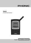
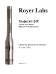
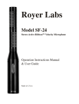
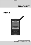
Q-Pro5 System INSTALLATION MANUAL Q-Pro5 System Installation Manual – September 2014 1 of 37 CONTENTS CONTENTS 2 INTRODUCTION 3 SYSTEM PARTS AND SPECIFICATIONS 4 SYSTEM INSTALLATION Locating and mounting the Drive Thru Base Locating and installing the Battery Charger Mounting the speaker and microphone Wiring and connecting the Order Point Drive Thru Base Connections to Order Point Drive Thru Base functions and settings Registering headsets and functionality Summary of Headset operating modes Road loop sensitivity adjustment Adjustment of inbound/outbound audio settings 5 6 7 8 9 10-13 13-16 17 18 19 CHECKLIST BEFORE LEAVING SITE 20 INSTALLATION FAULT FINDER 21-22 APPENDIX 1 – APPENDIX 2 – APPENDIX 3 – APPENDIX 4 – APPENDIX 5 – APPENDIX 6 – APPENDIX 7 – APPENDIX 8 – APPENDIX 9 – 23-24 25-26 27 28 29 30-31 32-33 34 35-36 Factory Default Settings Full Display Map/Advanced Settings Recording a Greet Message Using a Headset Trouble shooting Connecting a Sonar Detector Connecting a Drive Thru Timer Additional System Adjustments System Adjustments Made Manually Upgrading an Existing Pro5 Base to Side-By-Side Operation (SBS) or Dual Lane ADVANCE INFORMATION AND APPLICATIONS AVAILABLE FROM THE Q-DIGITAL WEBSITE. 1. Installation Manual 2. User Manual www.quaildigital.com Q-Pro5 System Installation Manual – September 2014 2 of 37 INTRODUCTION This manual is aimed at the technician level reader who is expected to be familiar with all safety precautions relevant to the use of electrical equipment. It will enable you to install a Q-Pro5 Drive Thru System at either a new or an up-grade site. You will also find detailed troubleshooting tables to identify and resolve any technical or user issues during your installation or post-completion. The manual is laid out as a step-by-step guide to installation procedure including the explanation of all basic features you’ll need to understand and relay to your customer. Please be familiar with all aspects of the installation and basic user features before you go to site. The Appendix provides tables, block diagrams and descriptions for implementation of more in-depth system features, further fault-finding, and wiring instructions to lane timers. If you have any further questions about the use of this equipment or safety issues, please contact Quail Digital or search our website support section where you can download PC applications and find extended information. The basic tools and equipment you’ll need for your installation are as follows: Drill and a 6mm drill bit Small terminal flat blade screwdriver No2 pozi screwdriver Electrical tape Tape measure Spirit level Marker pen Cable strippers/diagonal side cutters Soldering iron Solder www.quaildigital.com Q-Pro5 System Installation Manual – September 2014 3 of 37 SYSTEM PARTS AND SPECIFICATIONS The system comprises of the following components: Q-DTB QD DRIVE THRU BASE Frequency: Q-DT8 Power : DECT 1.88 GHz - 1.90GHz (License free and interference free) 12v 5A external power supply Dimensions H x W x D: 370mm x 300mm x 100mm Weight: 1.7 kg Repeaters: Up to 4 DECT repeaters Standard unit Comes with: Internal VDB, display for easier adjustments, Hands free order taking mode, Ethernet connectivity, message prompts, keypad messages for till support, message greeter, Q-buster, staff messages. Ready for dual lane upgrade without requiring extra unit. QD DRIVE THRU AIO HEADSET Frequency: DECT 1.88 GHz - 1.90GHz (License free and interference free) Power : 3.7V Li Polymer battery Weight: 0.100Kg Battery type: Removable and rechargeable Re-charge time 3 hours Battery duration 18 hours Q-DTCH Functions: Volume, T1, T2, Page Voice prompts for: Battery low, registered, registration mode, Out of range, Operating modes: PTT, Talk lock, VOX, sleep mode through movement sensor QD DRIVE THRU CHARGER QD-SPA Power : 12v 5A external power supply Dimensions H x W x D: 325mm x 205mm x 45mm Weight: 0.900Kg Installation: Desk top or wall mounted Capacity : 8 x battery packs Charge indicator: Dual colour LED changes from red to green when battery fully charged. QD DRIVE THRU SPEAKER AND MIC ASSEMBLY Speaker: Q-Pro5 System Microphone: 4” (100cm) driver. Power handling 14 watts. Impedance 8 ohms Sensitivity -38dBV/PA +/-3db. Impedance 50 ohms Dimensions H x W x D: 150mm x 150mm x 65mm Weight set: 0.300Kg Installation Manual – September 2014 4 of 37 SYSTEM INSTALLATION Installation Tip Before going to site it’s recommended you charge all the batteries (at your facility). If you don’t have the chance to charge the batteries prior to installation, install the charger first. STEP ONE LOCATING AND MOUNTING THE DRIVE THRU BASE The Q-Digital Base (Q-DTB) should be wall mounted in a location to maximise the range in the premises with access to a constant power-supply. When planning the best location, avoid placing the base in confined booths or narrow corridors. To gain maximum range make sure the base station is located in an open area (see below). Front counter Booth 2 Kitchen Booth 1 Possible locations Likely to restrict coverage Once you decide a final location for the base, it’s recommended you turn it on and test that it communicates with all headsets in the desired areas (see step 7 for headset registration). If you are installing a new system as part of a store up-grade remember the base may work better in a different location to the one you’re replacing. Should you require extra coverage, it is possible to install up to 4 repeaters. Please refer to our web site for more details on Q-Digital repeaters or see Appendix 4. You will need access to the display on the front panel, so do not mount the top of the Q-DTB higher than 2m (6’6”) from floor level. When choosing its location, make sure that you can fully open the front panel to make all connections comfortably. Q-DTB 2m max. Q-Pro5 System Installation Manual – September 2014 5 of 37 When you have chosen the correct location, locate the Q-DTB on the wall with the front door opened and mark the 4 wall fixing holes on the back of the base station for access to cables going into wall conduit. STEP TWO LOCATING AND INSTALLING THE CHARGER UNIT Q-DTCH Installation tip: The charger must remain plugged in at all times. Identify a power socket which is not shared with other equipment or is turned off at night. The system comes with an 8 port battery charger. The charger is always wall mounted via the two keyholes in the rear panel. Use the fixings supplied. Before mounting the charger on the wall, remember to insert the headsethanger metal bar, and plug in the power supply on the rear of the charger. When choosing the location for the charger, make sure that you have a 24hour power, that the batteries are easily accessible and the headsets can hang on the bar freely. Once the charger is secured on the wall, make sure you fix the security screw located on the 3rd slot bottom row. This will stop the charger from lifting off the wall when removing the batteries. Batteries should either be in a headset or in the charger. Systems are supplied with more batteries than headsets so make sure the spares are left in the charger. Batteries can be left in the headsets stored on the rack. The headsets have an in-built motion detector that cuts off battery power when the headset is not in use. (Moving the headset activates it again). This means that headsets with freshly charged batteries don’t need them removed at the end of the shift. Batteries will last for up to 18 hours between charges, slightly less on “talk lock” or “hands free” mode. A voice prompt ‘battery low’ indicates that user should swap the battery on their headset. Charge time is approximately 3 hours to full charge. When the batteries are charging, the LED on each charger port will indicate the status of each battery. Red when charging and green when fully charged. For your information, Quail Digital recommends replacement of batteries every 18 months. Q-Pro5 System Installation Manual – September 2014 6 of 37 STEP THREE MOUNTING THE SPEAKER AND THE MICROPHONE QD-SPK + QD-MIC The QD Pro5 system comes with a dedicated speaker and microphone. Alternative speakers or microphones should not be used with the system. QD-SPK QD-MIC You will notice your new system comes with a block of grey packing foam. This should be kept and used in the speaker post for sound insulation between the microphone and speaker. When fitting the microphone and speaker make sure that they are bolted flush to the two speaker post grills. Do not place them back from the front grills, otherwise you will increase echo and there will be a marked degradation in audio quality and voice clarity. Make sure all your cable connections are soldered. Soldering the cable joints reduces the likelihood of crackling and other interference on the headsets. QD-MIC QD-SPKR Q-Pro5 System Installation Manual – September 2014 7 of 37 STEP FOUR WIRING SPECIFICATION + CONNECTING from SPEAKER POST to BASE The cables you require are as follows: To connect the road loop to the Drive Thru Base you should use Belden 8760 OSP1/60 18awg 2 core grey cable. This is a single screened pair cable used to connect the Road Loop to the Vehicle Detector Board in the base station. LOOP CABLE SPECIFICATION: Belden Type 8760. OSP1/60. 18awg 2 core grey cable. AUDIO CABLE SPECIFICATION: Belden Type 8777. ISP3. 22AWG 3 pair grey cable. To connect Speaker and Microphone from order point to the Base you should use Belden Type 8777. ISP3. 22 AWG 3 pair grey cable. This has 3 pairs of cable, individually screened. Note: If you are using a single cable for both road loop and speaker/mic each wire needs individual screening to protect from interference. This is the wiring sequence for the speaker & mic in the base block connection. Wiring from top of connector down Speaker + Speaker - Green and red Both blacks from green & red pairs (only if the extra pair is not used by the loop) Mic + Mic Shield White Black from white pair Shield from white pair Installation tip: All outside cable joints MUST be soldered and grounded to avoid potential interference or crackle. Q-Pro5 System Installation Manual – September 2014 8 of 37 STEP FIVE Q-DRIVE THRU BASE CONNECTIONS TO ORDER POINT Q-VDB 3 105mm x 70mm On VDB 1 A com A n.o. B com A n.c. Reset B n.o. 12V + Loop Loop COD or order point 10 Gnd - 1 Green F1 White Microphone Shield F10 Black Black Spk + External connector to order point. Spk Mic + Mic Mic Scr + 12 V DT Module 1 V.Detect Red Speaker Aux.Detect GRD Spare Black Grill Spk Grill Spk + R com R. Detect R. Aux. Detect Aux. connector R.Tan R. Page Road loop R. T1 Spare Loop reset + 12 V (900mA fuse) GRD 12V IN DT BASE DRIVE THRU MODULE TO VDB INTERNAL CONNECTIONS DT BASE 12V IN F1 Spk + External Spk connector to Mic + Mic order point. Mic Scr + 12 V V.Detect Aux.Detect GRD Spare Grill Spk Grill Spk + R com R. Detect R. Aux. Detect Aux. R.Tan connector R. Page R. T1 Spare Loop reset + 12 V (900mA fuse) GRD 10 1 On Loop Loop Gnd 12V + Reset B n.o. B com A n.c. A n.o. A com VDB 1 F10 DT Module 1 Q-Pro5 System Installation Manual – September 2014 9 of 37 STEP SIX Q-DRIVE THRU BASE FUNCTIONS AND SETTINGS The Q-DTB has a user display interface where all functions and settings can be viewed and adjusted. This section explains the features you’ll see on the screen and how to make basic adjustments. The system comes configured to suit the needs of most drive thru operators, however Appendix 2 explains how to access the menu to activate or change features. The menu has 3 levels of password protection designed to ‘ring-fence’ parts of the menu that require adjustment by trained personnel. The Manager’s numeric password is 4895. It’s a fixed password giving the manager the ability to register new headsets and access basic functions to change date and time, night volume, language, etc. The second level is the installer’s numeric password is 1234 which you will need during your installation because it gives you access, for instance, to audio level settings, which are a critical part of your final adjustment procedure. The third is the technician’s password, restricted to Quail Digital trained technicians. This manual covers the Manager’s level and Installer’s level functions and settings. It is very unlikely you would be asked to make any further alterations requiring a higher level but if more advanced settings are required contact Quail Digital www.quaildigital.com . Q-Pro5 System Installation Manual – September 2014 10 of 37 SETTING TIME, DATE AND LANGUAGE When the unit is powered up, you will have to confirm the time and date in order to finalise the initialisation. If it’s incorrect for your time zone use the navigation arrows to the right of the screen to correct. If for any reason you missed the first prompt to adjust the time and date you can find it here: SETTINGS > SYSTEM SETTINGS > TIME AND DATE > ADJUST TIME AND DATE Next, if you require a different language to English, you can select from alternatives. SETTINGS > SYSTEM SETTINGS > LANGUAGE If you require a language that isn’t shown please contact Quail Digital. Selecting another language will change the language on the screen and the audio prompts in the headsets. This process is automatic and the display will show “headsets updating language”. The update may take several minutes (depending on the number of headsets). While the headsets are updating you will hear a busy tone and the headsets cannot be used. The process is terminated when the headset/s initialises in the new language and a beep is heard. The Pro5 system has been designed to be as ‘plug and play’ as possible. This is particularly so in the out-of-the-box readiness to work at optimum audio performance (inbound and outbound audio to and from speaker post and headsets). Whilst a great deal of adjustment is possible the system comes configured for your standard single lane drive thru with features ready-activated that are most commonly used. You will however be required to check and optimise the inbound noise cancelling level and speaker and mic levels despite them being factory-set at optimum levels for 90% of sites. SETTINGS: These are the features and information you will see permanently displayed on the base screen. You should familiarise yourself with each. Q-Pro5 System Installation Manual – September 2014 11 of 37 Time and date: Current time and date. This will need re-setting for your time zone. Software version: This is the software version running on your unit. Check with your distributor for latest version. Headsets registered: This is the total number of headset you have registered to your Q-DTB. Once you have gone through the registration procedure (Step 7) the display should read the same number of headsets as you’ve had delivered with the system. Repeaters: This field indicates if repeaters are active or not on the unit (see Appendix 4) Call: When active, indicates that at least one headset is in active use on the system. Keypads: This function is not used in drive thru applications. Grill Spk level: This indicates the current grill speaker volume. Its audio level can be adjusted “Up” and “Down” using the arrows on the navigation keypad. Lane 1: Indicates the status of the lane. Blank, when the lane is empty, “CAR” when a car arrives to the loop or detection device, “CAR” – “SERVING” when the order taker’s audio channel is open and attending the customer. There are 4 function buttons below the display Detection override: This function is always OFF in day-to-day operations. When turned ON, will allow the installer or the user to override the car detection device and simulate a vehicle presence at the order point. By pressing the T1 button on the headset, the inbound audio is opened. This function is mainly used for testing or in case the detection device is faulty. Night Volume: Night volume is used to reduce the audio level at the post at night time. Activation reduces volume by about 20%. The time can be linked to the real time clock and adjusted here: SETTINGS > SYSTEM SETTINGS > ADVANCE SETTINGS > AUTOMATIC NGHT VOLUME Split cross lane: This feature is inactive in a single lane drive thru configuration. In a dual lane drive thru press ‘split’ lane to operate 2 separate teams communicating with two separate order points. In this configuration Team 1 and Team 2 are entirely separate; they can only communicate with members of their own team. Once Split team is selected, you can choose your operating team by pressing Volume down – followed by T1 or T2 on your headset. ‘Cross’ lane can be used in a dual lane configuration when you want one order taker to take orders from both order points. In this configuration the order taker will hear arrival chimes from both order points, and will press corresponding T1 or T2. Crew members will hear orders from each order point as the order-taker switches between order points. Q-Pro5 System Installation Manual – September 2014 12 of 37 Hands free order taking: Hands free order taking is used by some operators; the vehicle detector opens and closes the call to one specific headset and the order taker doesn’t need to touch the headset to speak. However, only one headset can operate in this mode at any one time. Once the headset’s selected it’s the only one able to take the orders until the function is disabled on the base station by pressing the “hands free” button. It is still possible for any headset user to override the “order taker” by pressing T1 or T2 over 3 seconds until a blip is heard. Some customers like the hands free facility, but other do not. This facility has to be ‘positively’ activated by the installer having confirmed with customer. Go to settings (4895)>System Settings > Advanced Settings (43 + minutes reversed) >Disable/Allow Hands free STEP SEVEN REGISTERING THE HEADSETS AND FUNCTIONALITY Before using the system, each headset needs to be registered to the Base. This is a fundamental procedure and needs to be clearly understood. Any new or additional headset will also have to be registered with the base. The base takes a finite number of headsets, 6 is standard although bases with capacity of up to 12 headsets are available. Installation tip: When the Q-DTB is first powered up it takes about 20 seconds to fully boot up. Allow 20 seconds before starting the registration process. You should practice the registration procedure before you go to site. Q-Pro5 System Installation Manual – September 2014 13 of 37 Registering the headsets To initiate the registration process, follow these steps: 1. Make sure all the headsets are within range of the base station and are active with a battery connected. Active means you’ve lifted up the headset (removing it from sleep mode), inserted a charged battery and carried it to within range of the base station. If a headset already registered is not active when you start the registration process, it will be de-registered during the process. 2. Press the Registration button on the Q-DTB. 3. When prompted on screen with “Manager’s password”, insert 4895 using the screen display. 4. Press ok on the screen once you are sure that all headsets you wish to keep in the system are On, Active and within range. 5. On the new headset you wish to register, press Volume (down) first, followed by P (Page) (so both buttons are pressed together), until you hear a voice message saying “headset in registration mode.” You can release the two buttons at this stage. 6. As soon as a headset is registered, you will hear a message in the headset, saying ‘headset registered’ followed by an audible tone. At that point it’s ready to use. 7. Headsets previously registered do not need to be re-registered. Only follow step 5 above for headsets new to the site. 8. On the Q-DTB front panel you can press “Exit” or “Registration” to terminate the registration mode on the base or you can leave it to time-out, which it will do after 3 minutes. STEP EIGHT Headset functionality The headset has a movement sensor, which when it stops sensing movement for ten minutes will go into battery-saving sleep mode. When the headset is picked up, it will return to normal operation. You will hear ‘Initialising’ followed by a beep indicating the headset is active. (This process takes about 2 seconds.) The headset has the following built-in messages to help the user understand the status of the headset: “Headset not registered” - This message indicates that this is a new or serviced headset and has not yet been registered to your base. “Headset in Registration mode” – This message is heard when the headset is placed in registration mode. It will repeat this message until it has become registered to the base. Q-Pro5 System Installation Manual – September 2014 14 of 37 “Headset registered” – This message is heard twice just after the headset has established the link with the base during the registration process. “Initialising” –This is heard each time the headset is picked up and a battery connected. Once you hear a beep, the headset is ready for use. No action required by user. “Out of range” – This message is heard if the headset is out of range of the base, or if it has previously been registered to a different base which could be the case when a headset is back from repair, or it is swapped from another site. If this message is heard while the headset is next to the base, follow registration procedure above. “Battery low” - This message indicates that the battery is going flat and that you should replace it with a fully charged one. The headset has the following buttons and functions: Page “P” This is the paging channel that goes to all headset users only.. The page channel can operate in Push-to-Talk (PTT) by keep pressing the “P” button while you talk or Talk Lock (Hands Free) by pressing the “P” button momentarily (under 1 second) locking the headset to talk mode. To come out of Talk Lock press “P” once. T1 & T2 T1 (lane 1) and T2 (lane 2) are used to talk to the customer at the order point. If there is only one speaker post the headset defaults to channel 1 (T1). When a vehicle arrives you hear a single beep for lane 1 and a double beep for lane 2. The inbound audio will be opened as soon as the order taker presses T1 or T2. If the call is not attended a reminder beep will be heard every 5 seconds. (If the feature is enabled in the base) The order taker can also operate in Push-to-Talk (PTT) or Talk Lock (Hands-Free) as described in the Page section. Volume + & – This has a 5-stage range (+ -). When a headset is activated the default is level 3. Busy Tone If any headset user presses T1 or T2 by mistake while there is already an order taker, a busy tone will be heard and the order taker’s conversation with the customer is not interrupted. Busy tone is signalled by three short beeps. Overriding the order taker There can only be one order taker per lane at any one time. If another headset user or the manager wants to take over/interrupt the current order taker, they press T1 or T2 for over three seconds after which they hear a bleep confirming that they’ve now become the order taker. The former order taker will hear the busy tone to let them know that they are no longer the order taker. Q-Pro5 System Installation Manual – September 2014 15 of 37 Selecting a Team This feature enables sites to operate two teams in a single or dual lane drive thru system. The headset users can choose which team they interact with by pressing ‘Volume down & T1’ or ‘Volume down & T2’ to select a team. When T2 members want to speak to each other they press the P button. In a single lane configuration, one team can process orders via the speaker post, and a second team can process orders communicating between headsets on a second independent channel. In a Dual Lane configuration and when “split team” is selected, Team 1 and Team 2 are entirely separate; they can only communicate with members of their own team. Once Split team is selected, you can choose in what team you would like to operate. The headset always defaults to Team 1. Q-Pro5 System Installation Manual – September 2014 16 of 37 SUMMARY OF HEADSET OPERATING MODES Q-DT8 AIO HEAD SET FunctionStatus Action -Sequence Lane 1 LED Not registered Needs registration T1 Flashing blue twice every second Registered Internal call or Page channel T1 External call 1 T2 External call 2 Volume Up (+) Volume Down (-) Talk lock - T1 Flashing blue every 5 seconds Press Page button Fix Blue Press T1 button Fix Blue Press T2 button T1 fixed blue Registration Press Volume down + Page simultaneously for 3 seconds. (Volume down must be pressed first ) Fast flashing blue. Every second De-registration Take the battery out of the headsets and press the registration switch on the base. Low battery Remove battery and place it in the charger Out of range Walk nearer to the base or a repeater Press Volume down +T1 or Volume down + T2. (Volume down must be pressed first) Select “Hands Free OT mode” on the DTB display follow by T1 or T2 Push to Talk Select team Select Order Taker when “Hands Free order taking” mode is enabled on the DTB Override order taker Motion - sleep mode Press T1 or T2 for more than 3 seconds Head set is left without movement for 10 minutes T2 Flashing red every 5 seconds Fix red Communicates with lane 2. T2 fixed red Double blips will indicate max. and min. Levels. User can talk hands free. Back to normal operating status Fixed blue Fix red Off Off Off Turn headset off Remove battery or leave resting for 10 minutes Off Turn H/S On Insert fully charged battery or place it over your head. Depending on headset status (see modes above) Busy Tone T1 or T2 are pressed accidentally and there is already an order taker. Q-Pro5 System Description Audio message will say “Registration incomplete see manual” every 5 seconds Audio message will say “Headset registered” twice at the moment of registration. Communicates within team on the internal/page channel. Communicates with lane 1. Press + or - the volume button Press T1 or T2 or Page Switches for under a second. Press same switch T1, T2 or Page Press T1, T2 or Page Talk lock Off Lane 2 LED Installation Manual – September 2014 Communicates with lane 1 or lane 2 on Push to talk operation Head set on registration mode. The headset will return automatically to normal operating mode once it is registered or it will time out after 60 seconds. Flashing blue every 5 seconds. The base will automatically delete any Headset out of range or with no power. While doing this, make sure all working headsets you would like to keep registered are turned On and within range to the base. Audio message will say “Battery Low” Every 30 seconds, it will start 5 minutes before normal operation deteriorates. Audio message will say “Out of range” Every 15 seconds It will allow the user to select what team or lane they operate on and listen to. This sequence will allow the user to become the order taker when using the “Hands Free order taking” mode. Overrides the current order taker at any time and in any order taking mode. The Headset is equipped with a movement sensor which will put it in “sleep mode” after 10 minutes not sensing movement. As soon as the headset is picked up or moved will regain operation automatically. It will switch the headset off without losing registration. It will turn the headset on after being put on sleep mode. A busy tone will be heard. If pressed over 3 seconds it will override the current order taker. 17 of 37 STEP NINE Importance of a properly functioning road loop or saw cut loop The proper performance of the headset system depends to a great extent on the condition and quality of the road loop and associated cabling. A road loop that’s depreciated in quality will become less sensitive and this will mean the system may not detect each vehicle, resulting in the headset system failing to activate, and possible service calls. Whilst Quail Digital recommends NEW road loops on ALL old-store retrofits you will in any event need to check and set the sensitivity of the detection on every site you attend, new or old. Road Loop and VDB (Vehicle detection board) test procedure: 1. Once the system is installed you must check the number that’s displayed on the VDB when a vehicle arrives on the road loop. The optimum value is between 4 and 6 but if the loop isn’t sensitive enough, when a vehicle arrives on the loop the number displayed may drop as low as 1, or be over-sensitive and rise to 7 or 8. If the number alters above or below 4 or 6 you must manually adjust the sensitivity using the two up and down buttons shown below until the optimum values between 4 and 6 for every vehicle arriving onto the loop. VDB- QLMA1400 If the sensitivity needs to be set too high on the VDB to obtain the correct values, we recommend you to change the road loop. Q-Pro5 System Installation Manual – September 2014 18 of 37 STEP TEN Adjustment of inbound/outbound audio settings The system comes with default factory setting for inbound and outbound audio levels and noise cancelling. To reach the audio levels screen press: Settings/ Drive Thru settings / Audio settings / Audio levels If the road/external noise at the site is particularly bad, follow this procedure in the order described. FIRST, increase the inbound noise reduction from 3 to 4. If this doesn’t improve the clarity of the inbound audio return to default setting 3. THEN try increasing the microphone level at the order point from 2 to 3. Also try reducing level from 2 to 1. Judge which you think improves. If you choose to change the mic level GO BACK and try the inbound noise reduction level at 4 with the mic on the new level at order point (reducing the noise reduction to 4 might produce a better result than leaving it at the higher level.) If the sound level is too high at the speaker post (i.e. the order taker is too loud), reduce the speaker level at order point from 3 to 2 or 1. If there is a lot of echo in the speaker post (a) make sure the speaker and mic are separated properly with foam to deaden sound (see step 3) and (b) follow the procedure above. Note: never turn the echo cancelling off on a drive thru application. Q-Pro5 System Installation Manual – September 2014 19 of 37 CHECK EACH OF THESE BEFORE YOU LEAVE SITE 1. Charger The charger must have its own power supply and not be switched off at night. Check the security screw is fitted. Check all the battery slots work. Insert a battery into each, check RED LED illuminates on each. 2. Headsets Registration: Make sure all headsets are registered and receive/transmit audio in the range of the restaurant + booths. The system should be tested with 2 people. Test each headset Paging and T1/T2 functionality. 3. Vehicle Detection You must make sure the Road Loop sensitivity is adjusted properly which means you need to test it with cars on the loop. On a new store this may mean setting the levels with just one car, and it may need further adjustment later. On a retro-fit stay and monitor a range of vehicles. Can you hear the alert tone? Check the sensitivity reading on the VDB is between 4-6 on a consistent basis. 4. Audio levels Inbound audio: Testing the inbound audio level with a car engine running at the order point. When you hear the alert tone press T1 on the headset to open the inbound audio and talk to the person at the order point. Make sure you can clearly understand the orders. If you think it needs adjustment, go to STEP 10. Testing outbound audio: Making sure a car is at the post a car engine is running at the order point. While pressing T1 on the headset, the order taker voice should come out loud and clear. If you cannot be heard loud and clear, go to STEP 10. Detection Override Testing Detection Override: While wearing a headset and with no car present at the order point, press “Detection override” on the Q-DTB user interface display. You should hear the alert tone. Then press T1 on the headset to hear the inbound audio and communicate with the order point. Pressing T1 again will mute the outbound audio, inbound will be unaffected while the car is still present. Testing Hands Free Order Taking Testing Hands Free Order Taking: Select one headset to become the order taker headset. Then press “Hands Free order taking” on the display to turn this function on. When prompted, press T1 on the selected headset. You will get a message confirming that you are now the order taker. (If agreed with the customer and enabled) While wearing a headset and with no car present at the order point, press “Detection override” on the Q-DTB user interface display. You should hear the alert tone automatically followed by the inbound audio from the order point. The T1 channel to and from the order point is opened automatically by the car detection. Pressing T1 will mute the outbound audio, pressing it again will re-open the outbound audio channel. Q-Pro5 System Installation Manual – September 2014 20 of 37 Q-Pro5 System Installation Manual – September 2014 WHITE NOISE TRANSMITTED ON ALL HEADSETS NO OUTBOUND AUDIO AT THE ORDER POINT FIX and/or TESTS REQUIRED To establish inbound audio, you will need to have a car present. To simulate car present activate "detection override" and press T1 on the headset. Power issue or faulty DTM board. Check 12 V cables and power on the main board. Connect a spare mic directly to the Q-DTB base and activate "detection override". If you can hear the inbound properly with the new mic, you may have a problem with the cabling to the order point or with the mic installed. No power on the DTM board Faulty cabling to the order point If you have completed all the above checks and rebooted the base station several times, you may have a faulty DTM board. Check the LEDs on the DTM board inside the base. You should have one LED permanently on and a second one coming on when the car present Faulty DTM board Make sure you can hear your own voice when pressing "P" on the test headset Remove the battery on all headsets to reset them. If the noise is still there, reboot the base. Faulty mic boom on the headset/s Reset all headsets Speaker and Microphone cables reversed Whilst the system will work with the reverse wiring, it will sound very poor and you should double check connections at both ends. Connect a spare Speaker directly to the Q-DTB base and activate "detection override". Press T1 on a test headset and see if you can get outbound audio on the test speaker. If so you could have a faulty speaker or cabling to the order point. Faulty cabling to the order point or faulty speaker. Speaker and Microphone cables reversed Whilst the system will work with the reverse wiring, it will sound very poor and you should double check connections at both ends. Check the Mic at the order point. Is it fixed flush to the grill as possible? To maximise audio quality, the microphone should not be further than a meter from the customer. If you have completed all the above checks and rebooted the base station several times, you may have a faulty DTM board. Check the LEDs on the DTM board inside the base. You should have one LED permanently on and a second one coming on when the car present To establish whether there is a faulty cable or mic, connect a spare mic directly to the Q-DTB base and activate "detection override". If you can hear the inbound picked up by the new mic, you may have a problem with the cabling to the order point or with the mic installed. Microphone or cable to the order point Faulty DTM board Activate "Detection override" whilst wearing a headset and make sure you hear the alert tone. Then press T1. If you can hear the alert tone it means the sonar/loop is not working properly. Check cabling to the order point and sonar/loop. Faulty road loop or sensor Base did not initialise or reboot correctly Open the base. On the main DECT board there should be 3 x red LEDs lit and 1 x lit LED on the DTM board. When the car is present or "detection override" is activated you should see 4 lit red LEDS in the main board and 2 lit red LEDS in the DTM board. If you see none on the DTM or less than 3 on the main board, the system did not initialise correctly. Reboot the system. CHECK EACH OF THESE Is there a car present? INBOUND AUDIO DISTORTED OR Microphone fitted incorrectly LOW NO INBOUND AUDIO FROM THE ORDER POINT PROBLEM QD-PRO5 INSTALLATION FAULT FINDING TIPS INSTALLATION FAULT FINDER 21 of 37 Q-Pro5 System Installation Manual – September 2014 22 of 37 HEADSETS PLAYING ENGAGED TONE HEADSET WILL NOT REGISTER DISPLAY NOT WORKING ON BASE STATION NO ALERT TONE WHEN CAR ARRIVES LANE TWO NOT WORKING ON A DUAL LANE OR SBS SYSTEM SOFTWARE VERSION SHOWING 0.00-0.00 ON THE DISPLAY HEADSET KEEPS SAYING INITIALISING NO POWER ON HEADSET OR HEADSET KEEPS LOGGING OFF BASE STATION WILL NOT GO INTO REGISTRATION MODE PROBLEM Open the unit and check LEDs on the Main pcb and DTM pcb. You should see 3 x red LEDs (4 if a car present) on the main pcb and 1 red LED (2 if a car present) on the DTM pcb. If this LED pattern is not present, reset the base and re-register all headsets. Base did not reboot correctly "Hands free order taking" has been left ON Check the display on the base and make sure that "hands free order taking" is turned off Check DECT modules are fitted correctly Push DECT modules firmly in place and reboot the system. inside the Base User is pressing the wrong button on the Make sure the user is pressing T1 for lane 1 and T2 for lane 2. On a single lane, if the user presses T2 they will get the engaged tone. headset If the display shows 0.00-0.00, make sure the SD card is firmly in place and reboot the unit. Check power to the DT base and internal connections inside the base that feed the display board. Push down firmly on data and power cables. Power or internal connections Check software versions on the display Check the cabling to the order point for continuity. New cables should always be run. Loop and/or cabling Headsets need to be set up as two separate teams. To set up the second team press volume - followed by T2 on the team 2 headsets. Headsets are not set to Team/Lane 2 Make sure the VDB inside the Q-DTB has power and all cables and connections make good contact. Check that the onboard display shows a number. Check all internal connections and that the main board and DTM have 3 and 1 LEDs on respectively Base station did not boot correctly Vehicle detection board (VDB) If the display shows 0.00-0.00, reinsert the SD card and reboot the unit. If problem persists, replace or re-program SD card with replacement software from Quail Digital SD card or SD socket Make sure "Detection Override" is off on the Q-DTB display. If you register a larger number of headsets than allowed by the base (standard 6) the headset will not find an empty audio slot and it will stay on the initialising mode. Too many headsets registered to the base The detection override has been left on Raise the battery contacts on the headset slightly to make sure they touch the battery pack when inserted. Battery contact Make sure the base station is set to Dual lane or SBS. Go to settings/Drive Thru settings/Drive Thru Lay out. Remove and replace battery momentarily, if it still does not work try to re-register it. Headset locked up Base not set to Dual Lane Remove and replace battery momentarily, if it still does not work try to re-register it. Raise the battery contacts on the headset slightly to make sure they touch the battery pack when inserted. Battery contacts Headset locked up After pressing "registration" the Base goes back to the main screen and does not show "registration active" on the display. This indicates that there is no 12V DC going to the DTM or it is faulty. Check 12 V cable continuity and connections are solid. FIX and/or TESTS REQUIRED CHECK EACH OF THESE Possible DTM faulty or no power to the DTM QD-PRO5 INSTALLATION FAULT FINDING TIPS SINGLE LANE ENGLISH FACTORY PROFILE SPEAKER MICROPHONE OFF OFF ON PRESENCE POSITIVE OFF DT LAYOUT LANGUAGE PROFILE OUTPUT TYPE INPUT MESSAGE GREETER RETAIL MESSAGES CAR CLOSES CALL SENSOR TYPE DETECT INPUT DETECT DELAY DESCRIPTION Sets the type of configuration to single, dual lane or tandem Allows the user to select the menu language Allows the installers to revert back to the factory default settings Changes the output signal between speaker level or line level Changes the input signal between microphone level or line level Enables or disables the Message Greeter Enables or disables the Retail Messages If enabled, the car closes the call on the Order Taker headset automatically Allows you to select the sensor type between presence or pulse Allows you to select sensor signal polarity to Positive or Negative When R. Detect delay input is used, it allows you to set a delay on the sensor response time by keeping the level high during the time set. ALERT TONE REMINDER ON Repeats the alert tone (car arrival tone) every 5 seconds until the order taker presses T1 or T2 PAGE TO OWN HEADSET (SIDE TONE) ON When enabled, it allows the user to hear his/her own voice on the headset. It is useful to confirmed that mic and speaker are functioning correctly. It also confirms that the wireless link to the base is made. EXTERNAL TO OWN HEADSET OFF When enabled, it allows the user to hear his/her own voice. Normally turned Off to keep communication to the order point clearer. EXTERNAL AUDIO SENT TO PAGE ON When enabled, it allows all headset users to hear the customer at the order point. PAGE TO ORDER TAKER ON When enabled, it allows the order take to hear the page channel. This means that headset users can communicate with the order taker even when taking an order. EXTERNAL AUDIO ACTIVE ONLY WHEN CAR PRESENT In default it restricts audio going to the order point to when the car is present. Can be changed to all times. INBOUND OPENED BY T1/T2 ORDER TAKER Selects who opens the inbound audio, order take by pressing T1/T2 or automatically by the car. GRILL SPEAKER SETTINGS AUDIO LEVEL 3 Sets the grill/ kitchen ceiling speaker volume INBOUND ON If ON, it allows the inbound audio to be played on the grill speaker ALERT TONE ON If ON, it allows the alert tone to be played on the grill speaker PAGE CHANNEL OFF If ON, it allows audio from the page channel to be played on the grill speaker OUTBOUND OFF If ON, it allows the outbound audio to be played on the grill speaker PRE-ALERT TONE OFF If ON, it allows the Pre-alert tone to be played on the grill speaker (only if an extra loop is connected to the Aux. Detect) AUDIO LEVELS ECHO CANCELING ON Reduces the echo on the post. Do not turn this feature Off OUTBOUND NOISE REDUCTION 2 Reduces the level of kitchen noise picked up by the headsets. INBOUND NOISE REDUCTION 3 Reduces the level of engine noise and background noise at the order point. Maximum recommend is level 4. ALERT TONE LEVEL 3 Volume level for the alert tone played over the headsets SPEAKER LEVEL 3 Volume level of the speaker at the order point MICROPHONE LEVEL 3 Microphone volume at the order point FACTORY SETTING MAIN SYSTEM FUNCTIONS Q-DTB FACTORY DEFAULT SETTINGS APPENDIX 1 Q-Pro5 System FACTORY DEFAULT SETTINGS Installation Manual – September 2014 23 of 37 Q-Pro5 System Installation Manual – September 2014 24 of 37 DESCRIPTION Allows to turn this feature On or Off. When enabled it will play the message greeter at the order point Message greater volume Sets the delay for the message to start playing since the car arrives. It gives time to the order taker to attend the customer before the message start playing. If enabled, it will play the message greeter to the headsets. It allows the order taker to know when the message has finished FACTORY SETTING OFF 3 5 SEC ON MESSAGE GREETER MESSAGE GREETER MESSAGE GREETER LEVEL MESSAGE GREETER DELAY PLAY MESSAGE GREETER TO HS DESCRIPTION Allows to turn this feature On or Off. Retail Message volume If enabled, it will play the retail messages to the headsets If enabled, it will play the retail messages to the grill speaker DESCRIPTION Allows to turn this feature On or Off. When enabled it will play a "queue forming" message Target time for the car to be stationary on the pre loop Target time for the car to be stationary on the pre loop If enabled, it will play the Q-buster message to the headsets If enabled, it will play the Q-buster message to the grill speaker Q-BUSTER FACTORY SETTING Q-BUSTER OFF SET PRELOOP TIME 3 MIN SET ORDER POINT TIME 3 MIN PLAY Q-BUSTER TO HEADSETS ON PLAY Q-BUSTER TO GRILL SPEAKEROFF RETAIL MESSAGES FACTORY SETTING RETAIL MESSAGES OFF RETAIL MESSAGES LEVEL 3 PLAY RETAIL MESSAGE TO HS ON PLAY RETAIL M. TO GRILL SPEAKEROFF DESCRIPTION Allows to turn this feature On or Off. When On it will play the message prompts to the Order point. System prompts volume If On, it will play the System prompts to all headsets as well as to the order point. SYSTEM PROMPTS FACTORY SETTING SYSTEM PROMPTS OFF SYSTEM PROMPTS LEVEL 3 SYSTEM PROMPTS TO ALL HEADSETS OFF APPENDIX 2 FULL DISPLAY MAP/ADVANCED SETTINGS SYSTEM SETTINGS System reboot Time and date Languages Select profile Advanced settings Page audio to own headset. External audio to own headset. Disable/allow hands free Automatic night volume Audio output type DRIVE THRU SETTINGS Drive Thru Layout Car closes call Detection settings Loop reset Detect input Sensor type Vehicle detect delay Grill speaker settings Hear inbound Hear alert tone Hear page channel Hear Outbound Hear Pre- alert tone Grill speaker level Audio Settings Audio levels Outbound Noise Reduction Inbound Noise Reduction Echo cancelling Speaker Level at Order Point Mic Level at Order Point Alert tone Other Audio settings Ext. Audio sent to page Ext. Audio active when Inbound audio opened by Arrival tone reminder Page Channel to O.T. Q-Pro5 System Installation Manual – September 2014 25 of 37 MESSAGE SETTINGS System Prompts System Prompts on/off System Prompts level Play System Prompts to all headsets Q-Buster Q-Buster on/off Pre-Loop time Oder point time Play Q-Buster prompts to all Headsets Play Q-Buster prompts to Grill speaker Greeting Messages Greeting Messages on/off Manage Greeting messages Play Record Delete Use all day Disable Message greeter Level Message greeter play delay Play Message greeter to all Headsets Retail Messages Retail Messages on/off Retail Messages level Play Retail Message to all Headsets Play Retail Message to Grill speaker Manage Retail Messages Manage ID messages Manage Button messages Staff Messages Staff Messages on/off Manage Staff Messages Play Record Delete Disable Q-Pro5 System Installation Manual – September 2014 26 of 37 APPENDIX 3 RECORDING A GREET MESSAGE USING A HEADSET To record new Greet Messages and alter day part messages, it requires the Manager’s password and Installer’s password. On the DT base’s front display, follow the path below: Press Settings> (insert manager’s password 4895) then Message Settings> Greeting Messages > Manage Greeting Messages> (Installer’s password 1234) Then press play, record or Delete depending on the action you would like to take. To record new messages, you will need to have a very silent background and a QD headset. Make sure the headset’s microphone is positioned right in front of your mouth, then press the record button on the display to activate the recording and follow the instructions on screen. Please note, that you will need to keep pressing T1 on the headset for as long as the message is being recorded. You can then press play and listen to the new message on the headset to check if you are satisfied with the new recording. If not, you can repeat the process again. Once you have recorded your message, you can scroll to the right column using the left and right arrows and place the cursor over “not use” and allocate a time of the day when you would like this message to be played. Do this by using the up and down arrows. If you would like the message to be played all day you can simply press the “All Day” key at the bottom of the display. Q-Pro5 System Installation Manual – September 2014 27 of 37 Q-Pro5 System Installation Manual – September 2014 28 of 37 F1 1 10 F10 VDB 2 UI connector to DT Base R. T1 Spare Loop reset + 12 V (900mA fuse) GRD 12V IN Installation Manual – September 2014 Dect module 1 Dip switches : All to Off and 1 ON if using repeaters DTM 2 connec. UI connector ETH Sonar detector ON Dect module 2 Batt. 12V IN DTM 1 connec. 12V Out Cables void WALL SIDE Dect module 3 Blue = 12V - Connector to LCD Display contrast adjustment. Connector to front membrane Spk + External Spk connector to Mic + Mic order point. Mic Scr + 12 V V.Detect Aux.Detect GRD Spare Grill Spk Grill Spk + R com R. Detect R. Detect delay Aux. R.Tan connector R. Page Extra VDB and DT Module only required for Dual Lane systems. DT Module 2 Q-VDB 3 105mm x 70mm On Loop Loop Gnd 12V + Reset B n.o. B com A n.c. A n.o. A com Q-Pro5 System Brown= 12V + 8 DOOR SIDE Black = Sense out 12V 1 12V IN Dect module 4 DT BASE R. T1 Spare Loop reset + 12 V(900mA fuse) GRD Spk + External Spk connector to Mic + Mic order point. Mic Scr + 12 V V.Detect Aux.Detect GRD Spare Grill Spk Grill Spk + R com R. Detect R. Detect delay Aux. R.Tan connector R. Page APPENDIX 5 CONNECTING A SONAR DETECTOR DT Module 1 29 of 37 APPENDIX 6 CONNECTING A DRIVE THRU TIMER Q-Pro5 System Installation Manual – September 2014 30 of 37 Q-Pro5 System 1 2 3 4 5 6 7 8 9 10 11 12 13 14 15 16 Vehicle 1 Ground Vehicle 2 +12v Vehicle 3 Ground Vehicle 4 +12v Vehicle 5 Ground Vehicle 6 Control Greet 1 Greet 1 Greet 2 Greet 2 J5 CONNECTIONS 1 1 HME VDB101 Vehicle loop board 3 Installation Manual – September 2014 S18 Detector polarity J5 J2 1 S19 Greet detectors 16 HME VDB101 Vehicle loop board Service window loop HME System 30 main board RS232 J5 Q-VDB 3 105mm x 70mm 3 On On 1 1 1 2 3 4 5 6 SW19 SW18 12v AC RMT 12v AC RMT+ RMTRMT 12v AC 12v AC J2 CONNECTIONS 12 12 Set Greet 1 to Vehicle 2 Set Vehicle 1 to Negative for Quail DTM v4 Quail Digital to HME 30 timer F1 On 1 10 12V IN DT BASE Spk + External Spk connector to Mic + Mic order point. Mic Scr + 12 V V.Detect Aux.Detect GRD Spare Grill Spk Grill Spk + R com R. Detect R. Aux Detect Aux. R.Tan connector R. Page R. T1 Spare Loop reset + 12 V (900mA fuse) GRD F10 VDB 1 Loop Loop Gnd 12V + Reset B n.o. B com A n.c. A n.o. A com Cashier window loop or Single window CONNECTING A HME30 TIMER DT Module 1 31 of 37 APPENDIX 7 ADDITIONAL SYSTEM ADJUSTMENTS Here are four additional adjustments that may be required on an installation. 1. Screen contrast (lighter or darker) This adjustment is carried out by opening the Q-DTB and adjusting the contrast potentiometer surface mounted on the display pcb on the bottom right corner. 2. Road Loop sensitivity This adjustment is easily carried out on the vehicle detector board located at the top right of the Q-DTB. There are two surface mount buttons (up and down) that will allow you to adjust the sensitivity. Important Note: Where high vehicles are common we recommend to set the sensitivity to 6. See step 9. 3. Repeaters If the use of repeaters is required please switch number 1 switch on the 8 way dip switch to the ON position and add an extra Dect module. Please refer to Appendix 4 or Quail Digital. 4. Remote connectivity To connect to the unit remotely you will need to acquire the Pro5 PC application from Quail Digital and to configure the connectivity section on the display. Once you install the application on your PC, you can connect to the Q-DTB directly from any PC by using a standard network cable. In order to connect to the base via a direct link, all internal dip switches must be to the off position and you need to set your PC IP to 192.168.0.100 or similar. In order to connect to a Q-DTB remotely, you will need to insert all fields on the Base Station’s display under the connectivity section. To get to this section follow the path below. Settings (manager’s password)/ password ,1234)/ Configure. Connectivity Settings (installer’s Once you get to the “configure” screen you need to set: IP Address: Subnet mask: Gateway: (gateway of the restaurant’s router where the Q-DTB is installed and connected) UDP Port: (UDP of the restaurant’s router where the Q-DTB is installed and connected) the default is 48999. Another way to connect remotely is to load the PC application in the Customer’s PC (already in their network) and access this PC remotely. Q-Pro5 System Installation Manual – September 2014 32 of 37 Important Note: Remote connectivity and using the QD Pro5 PC application is an advance feature and gives access to all password protected functions on the system. Please make sure that you do not give access to this application to unqualified engineers or customers. On the table below we show the functions that can be configured by using the 8 way dip switch but that are NOT required for a standard installation. These switches are all set to OFF by default from the factory as required for a standard installation. Please see table function below for these dip switches. Switch 7 6 5 4 3 2 1 Q-Pro5 System Function Zone. Select one of the four possible settings and set the keypads to be used with this BS unit to the same zone setting. (Default = both off). Off = Normal master unit (default). On = Slave BS unit which will forward received keypad messages to a master unit via Ethernet. This is the only functionality the unit will provide. Off = Play keypad audio message sequence twice (default). On = Play keypad audio message sequence once Off = Use preset network setup as selected by DIP switch 3 (default). On = Use programmed network setup. Currently unused Off = DECT repeaters are not used On = DECT repeaters are used Installation Manual – September 2014 33 of 37 APPENDIX 8 SYSTEM ADJUSTMENTS MADE MANUALLY Q-Pro5 System Installation Manual – September 2014 34 of 37 APPENDIX 10 TO UPGRADE AN EXISTING PRO5 BASE STATION TO SIDE BY SIDE (SBS) OPERATION OR DUAL LANE You will need the following parts to complete the upgrade; these are supplied by Q Digital, complete, as an SBS upgrade kit 1 x Vehicle detector board PCB (VDB) 1 x Drive thru module PCB 1 x Ribbon cable 1 x PCB interconnect power cable 1 x DECT module 8 x mounting screws 3 x Additional headsets complete with batteries 1) Power off existing Pro 5 base station. 2) In one of the spare slots at the bottom of the main pcb, adjacent to the existing DECT modules, carefully plug in the additional DECT module, ensuring it is located correctly on the connector pins 3) On the back of the base door, there are 8 mounting posts provided for the additional circuit boards. Using 4 of the screws provided, on the top 4 mounts, screw the new vehicle detector board into position. (VDB 2) 4) On the lower 4 mounts, again using 4 of the screws provided, mount the new Drive Thru module PCB (DTM2) 5) Using the diagram on page 35, locate the “DTM2” ribbon connector socket on main PCB and plug in the supplied ribbon cable to corresponding connector on DTM2 6) On the main PCB, locate the spare 12 volt out plug (located just below main power in connector) and plug in the power lead supplied, and connect to corresponding 12 volt in on DTM 2 7) Now wire the power, reset, and detection wires from VDB2 to DTM 2 as shown in illustration. (wiring is the same as DTM1 and its corresponding VDB1) a. b. c. d. e. DTM2 + 12V V. Detect Loop reset +12v GRD VDB 2 A Com A n.o. Reset 12v+ Gnd- 8) Wire the loop, microphone and speaker from COD2 to DTM2 on the Pro5 base door. Connections are the same as those for COD1 to DTM1 as shown in the main instruction manual, page 6. 9) When all wiring is complete and checked, you can proceed to power on the Pro5 base. Now that the wiring is complete, you need to activate the SBS function of the Pro5 base. Q-Pro5 System Installation Manual – September 2014 35 of 37 10) From the main menu on screen, a. b. c. d. e. Press the “settings” button and enter the managers access code of 4895 Press “drive thru settings” Press “drive thru layout” then enter the ENGINEERS password Select and highlight, from the list of options, the “Dual Lane” option. Press exit several times to return to the main screen. 11) Following the procedure from page 17 of the main manual, register the new headsets to the system. Make sure all existing headsets have batteries in, and are in range of the base while registering new headsets, or they will be de-registered during the process. Cross – One order taker can attend both lanes and all headsets stay on team 1. Page channel behaves as in single lane. Split – Headsets must be split in two teams and the page channel is independent between the two teams. This means that team 1 will only hear the alert tone and customer from COD 1 and team 2 will only hear the alert tone and customer from COD2. NOTE. In SPLIT operation, Team 1 members cannot take orders from COD2, and Team 2 members cannot take orders from COD1. Team 1 and 2 members can only speak to other members of their team using the page button, and not members of the other team. Finally all levels and audio settings can be set up as required, to suit the particular environment of the specific site. Level settings are common to both COD1 and COD2 Q-Pro5 System Installation Manual – September 2014 36 of 37 Quail Digital UK 92 Lots Road, London SW10 0QD Tel: +44 (0)20 7349 2000 Email: [email protected] Quail Digital Europe Zum Ueltgesforthof 14 47441 Moers Germany Tel: +49 (0)2841 88605 50 Email: [email protected] Quail Digital North America 200 East Randolph Street, Suite 5100 Chicago, IL 60601 Email: [email protected] Tel: 1-888-575-1010 Quail Digital, 92 Lots Road, London, SW10 0QD, E: [email protected] W: www.quaildigital.com Q-Pro5 System Installation Manual – September 2014 37 of 37