1
Teiid Designer User Guide
1
8.1.0
1. Introduction ................................................................................................................. 1
1.1. What is Teiid Designer? ...................................................................................... 1
1.2. Metadata Overview ............................................................................................. 2
1.2.1. What is Metadata ..................................................................................... 2
1.2.2. Business and Technical Metadata ............................................................. 4
1.2.3. Design-Time and Runtime Metadata ......................................................... 5
1.2.4. Source and View Metadata ....................................................................... 6
1.3. It's all in the Modeling... .................................................................................... 10
1.3.1. What Are Models? ................................................................................. 10
1.3.2. How is a Model Defined? ....................................................................... 11
1.3.3. Guiding through the process ................................................................... 12
1.3.4. Targeting the Right Teiid Server .............................................................. 12
1.3.5. Model Classes and Types ...................................................................... 13
1.3.6. The Virtual Database .............................................................................. 13
1.3.7. Model Validation .................................................................................... 15
1.3.8. Testing Your Models .............................................................................. 15
1.3.9. Model Object Extensions ........................................................................ 16
2. Dive Right In! .............................................................................................................
2.1. Targeting the Teiid Server .................................................................................
2.1.1. Server Version Preference ......................................................................
2.1.2. Defining a Teiid Server ...........................................................................
2.1.3. Server Version Status Panel ...................................................................
2.2. Guide Example .................................................................................................
2.2.1. Model a JDBC Source ............................................................................
2.3. Cheat Sheet Example .......................................................................................
2.3.1. Consume a SOAP Web Service ..............................................................
3. New Model Wizards ...................................................................................................
3.1. Creating New Relational Source Model ..............................................................
3.1.1. Generate File Translator Procedures .......................................................
3.1.2. Generate Web Service Translator Procedures ..........................................
3.1.3. Copy From Existing Model ......................................................................
3.2. Creating New Relational View Model .................................................................
3.2.1. Copy From Existing Model ......................................................................
3.2.2. Transform From Existing Model ..............................................................
3.3. Creating XML Document View Model .................................................................
3.3.1. Copy From Existing Model ......................................................................
3.3.2. Build XML Documents From XML Schema ..............................................
3.4. Creating XML Schema Model ............................................................................
3.4.1. Copy From Existing Model ......................................................................
3.5. Creating Web Service View Model .....................................................................
3.5.1. Copy From Existing Model ......................................................................
3.5.2. Build From Existing WSDL File(s) or URL ................................................
3.5.3. Build From Relational Models .................................................................
3.5.4. Build From XML Document View Models .................................................
19
19
19
20
21
22
22
37
37
51
52
53
54
56
57
58
59
59
59
60
64
65
65
66
67
67
68
iii
Teiid Designer User Guide
4. Importers ................................................................................................................... 71
4.1. Import DDL ....................................................................................................... 71
4.2.
4.3.
4.4.
4.5.
4.6.
4.7.
Import From JDBC Database ............................................................................. 74
Import From Teiid Data Source Connection ........................................................ 80
Import From Flat File Source ............................................................................. 84
Import From XML Data File Source .................................................................... 98
Import From Salesforce ................................................................................... 105
Import Metadata From Text File ....................................................................... 110
4.7.1. Import Relational Model (XML Format) ................................................... 111
4.7.2. Import Relational Tables (CSV Format) .................................................. 115
4.7.3. Import Relational View Tables (CSV Format) .......................................... 117
4.8. Import WSDL into Relational Models ................................................................ 119
4.8.1. Circular References in WSDL Schemas ................................................. 125
4.9. Import WSDL Into Web Service ....................................................................... 126
4.9.1. Import WSDL From Workspace Location ............................................... 127
4.9.2. Import WSDL From File System Location ............................................... 133
4.9.3. Import WSDL From URL ....................................................................... 139
4.10. XSD Schema File ..........................................................................................
5. Creating and Editing Model Objects ........................................................................
5.1. Creating New Model Objects ...........................................................................
5.1.1. New Child Action ..................................................................................
5.1.2. New Sibling Action ...............................................................................
5.1.3. New Association Action ........................................................................
5.2. New Model Object Wizards .............................................................................
5.2.1. Create Relational Table Wizard .............................................................
5.2.2. Create Relational Procedure Wizard ......................................................
5.2.3. Create Relational Index Wizard .............................................................
5.2.4. Create View Model Objects Wizards ......................................................
5.3. Model Object Editors .......................................................................................
5.3.1. Transformation Editor ...........................................................................
5.3.2. Input Set Editor (XML) ..........................................................................
5.3.3. Choice Editor (XML) .............................................................................
5.3.4. Recursion Editor (XML) .........................................................................
5.3.5. Operation Editor ...................................................................................
5.4. Managing Model Object Extensions .................................................................
5.4.1. Create New MED .................................................................................
5.4.2. Edit MED .............................................................................................
5.4.3. Extending Models With MEDs ...............................................................
5.4.4. Setting Extended Property Values .........................................................
6. Metadata-specific Modeling .....................................................................................
6.1. Relational Source Modeling .............................................................................
6.1.1. Source Function ...................................................................................
6.1.2. Create Relational Table Wizard .............................................................
6.2. Relational View Modeling ................................................................................
iv
145
151
151
151
154
156
158
158
159
163
164
165
167
185
187
190
194
195
196
197
201
202
205
205
205
208
214
6.2.1. Create Materialized Views ..................................................................... 214
6.2.2. Create Relational View Table Wizard ..................................................... 218
6.3. XML Document Modeling ................................................................................
6.3.1. Create XML View Documents from schema ...........................................
6.4. Web Services Modeling ...................................................................................
6.4.1. Create Web Service Action ...................................................................
6.4.2. Web Services War Generation ..............................................................
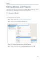
7. Editing Models and Projects ....................................................................................
7.1. Rename A Model ............................................................................................
7.2. Move Model ....................................................................................................
7.3. Save Copy of Model .......................................................................................
7.4. Clone Project ..................................................................................................
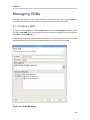
8. Managing VDBs .......................................................................................................
8.1. Creating a VDB ..............................................................................................
8.2. Editing a VDB .................................................................................................
8.3. Test a VDB ....................................................................................................
8.4. Multi-source Binding Support ...........................................................................
222
222
226
226
228
241
241
242
244
246
249
249
250
250
250
8.5. UDF support ...................................................................................................
8.6. Reusing VDBs ................................................................................................
9. Testing Your Models ................................................................................................
9.1. Manage Connection Profiles ............................................................................
9.1.1. Set Connection Profile for Source Model ................................................
9.1.2. View Connection Profile for Source Model .............................................
9.1.3. Remove Connection Profile from Source Model ......................................
9.2. Previewing Data For a Model ..........................................................................
9.2.1. Preview Relational Table or View ..........................................................
9.2.2. Preview Relational Table With Access Pattern ........................................
9.2.3. Preview Relational Procedure ...............................................................
9.2.4. Preview Web Service Operation ............................................................
9.2.5. Sample SQL Results for Preview Data ...................................................
9.2.6. Execution Plans ...................................................................................
9.3. Testing With Your VDB ...................................................................................
9.3.1. Creating Data Sources .........................................................................
9.3.2. Execute VDB from Model Explorer ........................................................
9.3.3. Deploy VDB from Model Explorer ..........................................................
9.3.4. Executing a Deployed VDB ...................................................................
10. Searching ...............................................................................................................
10.1. Finding Model Objects ...................................................................................
10.2. Search Transformation SQL ...........................................................................
10.3. Search Models Via Metadata Properties .........................................................
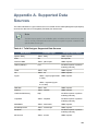
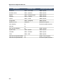
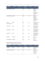
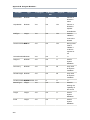
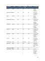
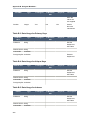
A. Supported Data Sources ............................................................................................
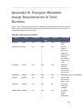
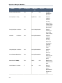
B. Designer Metadata Usage Requirements In Teiid Runtime ...........................................
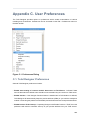
C. User Preferences ......................................................................................................
C.1. Teiid Designer Preferences .............................................................................
251
252
259
259
259
259
261
261
262
263
264
265
266
267
268
268
270
271
272
279
279
281
283
285
287
299
299
v
Teiid Designer User Guide
C.1.1. Diagram Preferences ........................................................................... 301
C.1.2. Diagram Printing Preferences ............................................................... 302
C.1.3. Editor Preferences ...............................................................................
C.1.4. Validation Preferences .........................................................................
D. Teiid Designer Ui Reference ......................................................................................
D.1. Teiid Designer Perspectives ............................................................................
D.1.1. Teiid Designer Perspective ...................................................................
D.1.2. Opening a Perspective .........................................................................
D.1.3. Further information ...............................................................................
D.2. Teiid Designer Views ......................................................................................
D.2.1. Model Explorer View ............................................................................
D.2.2. Outline View ........................................................................................
D.2.3. Server View .........................................................................................
D.2.4. Properties View ...................................................................................
D.2.5. Description View ..................................................................................
D.2.6. Problems View ....................................................................................
D.2.7. Search Results View ............................................................................
303
306
311
311
311
313
315
315
315
318
320
327
329
331
333
D.2.8. Datatype Hierarchy View ......................................................................
D.2.9. Teiid Model Classes View ....................................................................
D.2.10. System Catalog View .........................................................................
D.2.11. SQL Reserved Words View ................................................................
D.2.12. Model Extension Definition Registry View (MED Registry View) .............
D.2.13. Guides View ......................................................................................
D.2.14. Status View .......................................................................................
D.2.15. Cheat Sheets View ............................................................................
D.3. Editors ...........................................................................................................
D.3.1. Model Editor ........................................................................................
D.3.2. VDB Editor ..........................................................................................
D.3.3. Model Extension Definition Editor ..........................................................
D.4. Teiid Designer Main Menu ..............................................................................
D.4.1. File Menu ............................................................................................
D.4.2. Edit Menu ............................................................................................
D.4.3. Refactor Menu .....................................................................................
D.4.4. Navigate Menu ....................................................................................
D.4.5. Search Menu .......................................................................................
D.4.6. Project Menu .......................................................................................
D.4.7. Metadata Menu ....................................................................................
D.4.8. Run Menu ...........................................................................................
D.4.9. Window Menu ......................................................................................
D.4.10. Help Menu .........................................................................................
335
336
337
338
339
340
342
343
344
346
365
371
374
375
378
379
380
380
382
383
383
384
385
vi
Chapter 1.
Introduction
The Teiid Designer User's Guide provides detailed descriptions of Teiid Designer features and
functionality.
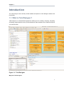
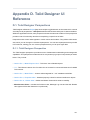
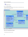
1.1. What is Teiid Designer?
Teiid Designer is an Eclipse-based graphical modeling tool for modeling, analyzing, integrating
and testing multiple data sources to produce Relational, XML and Web Service Views that expose
your business data.
Figure 1.1. Teiid Designer
Why Use Teiid Designer?
1
Chapter 1. Introduction
Teiid Designer is a visual tool that enables rapid, model-driven definition, integration and testing of
data services without programming. With Teiid Designer , not only do you map from data sources
to target formats using a visual tool, but you can also:
• resolve semantic differences
• create virtual data structures at a physical or logical level
• use declarative interfaces to integrate, aggregate, and transform the data on its way from source
to a target format which is compatible and optimized for consumption by your applications
This allows you to abstract the structure of the information you expose to and use in your
applications from the underlying physical data structures. With Teiid Designer, data services are
defined quickly, the resulting artifacts are easy to maintain and reuse, and all the valuable work
and related metadata are saved for later reference.
You can use Teiid Designer to integrate multiple sources, and access them using the common
data access standards:
• Web Services / SOAP / XML
• JDBC / SQL
• ODBC / SQL
Teiid Designer is an integral part of the Teiid Designer enterprise-class system for providing data
services for service-oriented architectures.
1.2. Metadata Overview
1.2.1. What is Metadata
Metadata is data about data. A piece of metadata, called a meta object in the Teiid Designer,
contains information about a specific information structure, irrespective of whatever individual data
fields that may comprise that structure.
Let’s use the example of a very basic database, an address book. Within your address book you
certainly have a field or column for the ZIP code (or postal code number). Assuming that the
address book services addresses within the United States, you can surmise the following about
the column or field for the ZIP code:
• Named ZIPCode
• Numeric
• A string
• Nine characters long
• Located in the StreetAddress table
2
What is Metadata
• Comprised of two parts: The first five digits represent the five ZIP code numbers, the final four
represent the ZIP Plus Four digits if available, or 0000 if not
• Formatted only in integer numeric characters. Errors will result if formatted as 631410.00 or
6314q0000
This definition represents metadata about the ZIP code data in the address book database. It
abstracts information from the database itself and becomes useful to describe the content of
your enterprise information systems and to determine how a column in one enterprise information
source relates to another, and how those two columns could be used together for a new purpose
You can think of this metadata in several contexts:
• What information does the metadata contain? (see Section 1.2.2, “Business and Technical
Metadata”)
• What data does the metadata represent? (see Section 1.2.4, “Source and View Metadata”)
• How will my organization use and manage this metadata? (see Section 1.2.3, “Design-Time
and Runtime Metadata”)
Editing Metadata vs. Editing Data
The Teiid Designer helps you to create and describe an abstract graphic representation of your
data structure of your data in the original data sources. It also describes whether those data
sources are composed of Relational databases, text files, data streams, legacy database systems,
or some other information type.
The Teiid Designer allows you to create, edit, and link these graphically-represented meta objects
that are really a description of your data, and not the data itself.
So when this documentation describes the process of creating, deleting, or editing these meta
objects, remember that you are not, in fact, modifying the underlying data.
Metadata Models
A metadata model represents a collection of metadata information that describes a complete
structure of data.
In a previous example we described the field ZIPCode as a metadata object in an address book
database. This meta object represents a single distinct bit of metadata information. We alluded
to its parent table, StreetAddress. These meta objects, and others that would describe the other
tables and columns within the database, would all combine to form a Source Metadata model for
whichever enterprise information system hosts all the objects.
You can have Source Models within your collection of metadata models These model physical
data storage locations. You can also have View Models, which model the business view of the
data. Each contains one type of metadata or another. For more information about difference
between Source and View metadata, (see Section 1.2.4, “Source and View Metadata”).
3
Chapter 1. Introduction
Note
For detailed information about creating models from your metadata, see
Section 1.3, “It's all in the Modeling...”
1.2.2. Business and Technical Metadata
Metadata can include different types of information about a piece of data.
• Technical metadata describes the information required to access the data, such as where the
data resides or the structure of the data in its native environment.
• Business metadata details other information about the data, such as keywords related to the
meta object or notes about the meta object.
Note
The terms technical and business metadata, refer to the content of the metadata,
namely what type of information is contained in the metadata. Don’t confuse
these with the terms “physical” and “view” metadata that indicate what the
metadata represents. For more information, (see Section 1.2.4, “Source and View
Metadata”).
Technical Metadata
Technical metadata represents information that describes how to access the data in its original
native data storage. Technical metadata includes things such as datatype, the name of the data
in the enterprise information system, and other information that describes the way the native
enterprise information system identifies the meta object
Using our example of an address book database, the following represent the technical metadata
we know about the ZIP code column:
• Named ZIPCode
• Nine characters long
• A string
• Located in the StreetAddress table
• Uses SQL Query Language
These bits of information describe the data and information required to access and process the
data in the enterprise information system.
4
Design-Time and Runtime Metadata
Business Metadata
Business metadata represents additional information about a piece of data, not necessarily related
to its physical storage in the enterprise information system or data access requirements. It can
also represent descriptions, business rules, and other additional information about a piece of data.
Continuing with our example of the ZIP Code column in the address book database, the following
represents business metadata we may know about the ZIP code:
• The first five characters represent the five ZIP code numbers, the final four represent the ZIP
Plus Four digits if available, or 0000 if not
• The application used to populate this field in the database strictly enforces the integrity of the
data format
Although the first might seem technical, it does not directly relate to the physical storage of
the data. It represents a business rule applied to the contents of the column, not the contents
themselves.
The second, of course, represents some business information about the way the column was
populated. This information, although useful to associate with our definition of the column, does
not reflect the physical storage of the data.
1.2.3. Design-Time and Runtime Metadata
Teiid Designer software distinguishes between design-time metadata and run-time metadata. This
distinction becomes important if you use Teiid Designer Server. Design-time data is laden with
details and representations that help the user understand and efficiently organize metadata. Much
of that detail is unnecessary to the underlying system that runs the Virtual Database that you will
create. Any information that is not absolutely necessary to running the Virtual Database is stripped
out of the run-time metadata to ensure maximum system performance.
Design-Time Metadata
Design-time metadata refers to data within your local directory that you have created or have
imported. You can model this metadata in Teiid Designer, adding Source and View metadata.
Runtime Metadata
Once you have adequately modeled your enterprise information systems, including the necessary
technical metadata that describes the physical structure of your sources, you can use the metadata
for data access.
To prepare the metadata for use in Teiid Designer Server, you take a snapshot of a metadata
model for Teiid Designer Server to use when resolving queries from your client applications. This
run-time metadata represents a static version of design-time metadata you created or imported.
This snapshot is in the form of a Virtual Database definition, or VDB.
5
Chapter 1. Introduction
As you create this runtime metadata, Teiid Designer:
• derives the runtime metadata from a consistent set of metadata models.
• creates a subset of design-time metadata, focusing on the technical metadata that describes
the access to underlying enterprise information systems.
• optimizes runtime metadata for data access performance.
You can continue to work with the design-time metadata, but once you have created a runtime
metadata model, it remains static.
1.2.4. Source and View Metadata
In addition to the distinction between business and technical metadata, you should know the
difference between Source Metadata and View Metadata.
Source and View metadata refer to what the metadata represents, not its content.
Source Metadata directly represents metadata for an enterprise information system and captures
exactly where and how the data is maintained. Source Metadata sounds similar to technical
metadata, but Source Metadata can contain both technical and business metadata. When you
model Source Metadata, you are modeling the data that your enterprise information systems
contain.
View Metadata, on the other hand, represent tailored views that transform the Source Metadata
into the terminology and domain of different applications. View Metadata, too, can contain both
technical and business metadata. When you model View Metadata, you’re modeling the data as
your applications (and your enterprise) ultimately use it.
Modeling Your Source Metadata
When you model the Source Metadata within your enterprise information systems, you capture
some detailed information, including:
• Identification of datatype
• Storage formats
• Constraints
• Source-specific locations and names
The Source Metadata captures this detailed technical metadata to provide a map of the data, the
location of the data, and how you access it.
This collection of Source Metadata comprises a direct mapping of the information sources within
your enterprise. If you use the Teiid Designer Server for information integration, this technical
metadata plays an integral part in query resolution.
6
Source and View Metadata
For example, our ZIPCode column and its parent table StreetAddress map directly to fields within
our hypothetical address book database.
To extend our example, we might have a second source of information, a comma-separated text
file provided by a marketing research vendor. This text file can supply additional demographic
information based upon address or ZIP code. This text file would represent another Enterprise
Information System (EIS), and the meta objects in its Source Model would describe each commaseparated value.
Modeling Your View Metadata
When you create View Metadata, you are not describing the nature of your physical data storage.
Instead, you describe the way your enterprise uses the information in its day-to-day operations.
View Metadata derives its classes and attributes from other metadata. You can derive View
Metadata from Source Metadata that describes the ultimate sources for the metadata or even
from other View Metadata. However, when you model View Metadata, you create special “views”
on your existing enterprise information systems that you can tailor to your business use or
application expectations. This View Metadata offers many benefits:
• You can expose only the information relevant to an application. The application uses this View
Metadata to resolve its queries to the ultimate physical data storage.
• You can add content to existing applications that require different views of the data by adding
the View Metadata to the existing View Metadata that application uses. You save time and
effort since you do not have to create new models nor modify your existing applications.
• Your applications do not need to refer to specific physical enterprise information systems,
offering flexibility and interchangeability. As you change sources for information, you do not
have to change your end applications.
• The View Metadata models document the various ways your enterprise uses the information
and the different terminology that refers to that information. They do so in a central location.
Our example enterprise information sources, the address book database, and the vendor-supplied
comma-delimited text file, reside in two different native storage formats and therefore have two
Source Metadata models. However, they can represent one business need: a pool of addresses
for a mass mailing.
By creating a View Metadata model, we could accurately show that this single View Table,
the AddressPool, contains information from the two enterprise information systems. The View
Metadata model not only shows from where it gets the information, but also the SQL operations
it performs to select its information from its source models.
This View Metadata can not only reflect and describe how your organization uses that information,
but, if your enterprise uses the Teiid Designer Server, your applications can use the View
Metadata to resolve queries.
7
Chapter 1. Introduction
To create this View Metadata, you create a view and define a transformation for that view, a
special query that enables you to select information from the source (or even other view) metadata
models. For more information, see “Section 5.3.1, “Transformation Editor”.”
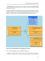
Metadata Transformations
By modeling View Metadata, you can illustrate the business view of your enterprise information
sources. View Metadata models not only describe that business view, but also illustrate how
the meta objects within the View Metadata models derive their information from other metadata
models.
Let’s return to the example of our address book database and the vendor’s comma-separated list.
We want to generate the View Metadata model, Address Pool, from these enterprise information
systems.
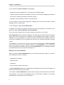
Figure 1.2. Data Flow for View Transformations
The transformation that joins these metadata models to create the virtual Address Pool metadata
model contains a SQL query, called a union, that determines what information to draw from the
source metadata and what to do with it.
The resulting Address Pool contains not only the address information from our Address Book
database, but also that from our vendor-supplied text file.
SQL in Transformations
8
Source and View Metadata
Transformations contain SQL queries that SELECT the appropriate attributes from the information
sources.
For example, from the sources the transformation could select relevant address columns, including
first name, last name, street address, city, state, and ZIP code. Although the metadata models
could contain other columns and tables, such as phone number, fax number, e-mail address, and
Web URL, the transformation acts as a filter and populates the Address Pool metadata model with
only the data essential to building our Address Pool.
You can add other SQL logic to the transformation query to transform the data information. For
example, the address book database uses a nine-character string that represents the ZIP Plus
Four. The transformation could perform any SQL-supported logic upon the ZIPCode column to
substring this information into the format we want for the Address Pool View metadata model.
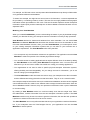
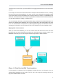
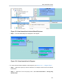
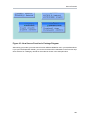
Mapping XML Transformations
When you model View Metadata, you can also create a View XML Document model. This View
Document lets you select information from within your other data sources, just like a regular View
Metadata model, but you can also map the results to tags within an XML document.
Figure 1.3. Data Flow for XML Transformations
In this example, the Address Pool View Metadata model still selects its information from the
Address Book Database and the Vendor Text File, but it also maps the resulting columns into
tags in the Address XML document.
9
Chapter 1. Introduction
1.3. It's all in the Modeling...
1.3.1. What Are Models?
A model is a representation of a set of information constructs. A familiar model is the relational
model, which defines tables composed of columns and containing records of data. Another familiar
model is the XML model, which defines hierarchical data sets.
In Teiid Designer, models are used to define the entities, and relationships between those entities,
required to fully define the integration of information sets so that they may be accessed in a uniform
manner, using a single API and access protocol. The file extension used for these models is .xmi
( Example: NorthwindOracle.xmi ) which adheres to the XMI syntax defined by the OMG.
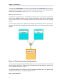
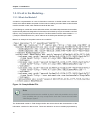
Below is an example of the partial contents of a model file.
Figure 1.4. Sample Model File
Note
Model files should never be modified "by hand". While it is possible to do so, there
is the possibility that you may corrupt the file such that it cannot be used within
Teiid Designer system.
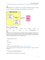
The fundamental models in Teiid Designer define the structural and data characteristics of the
information contained in data sources. These are referred to as source models (represented by
10
How is a Model Defined?
). Teiid Designer uses the information in source models to federate the information in multiple
sources, so that from a user's viewpoint these all appear to be in a single source.
Figure 1.5. Model Internals
In
addition
ability
to
to
define
source
a
models,
Teiid
Designer
provides
variety
of
view
models(represented
the
by
). These can be used to define a layer of abstraction above the physical (or source) layer, so
that information can be presented to end users and consuming applications in business terms
rather than as it is physically stored. Views are mapped to sources using transformations between
models. These business views can be in a variety of forms:
• Relational Tables and Views
• XML
• Web services
• Functions
For full list of supported model types see Chapter 3, New Model Wizards
A third model type, logical, provides the ability to define models from a logical or structural
perspective.
1.3.2. How is a Model Defined?
Models are defined using Teiid Designer in various ways:
11
Chapter 1. Introduction
• Created via importing source data characteristics. (see Chapter 4, Importers)
• Manual creation via Chapter 3, New Model Wizards
• Transforming or copying from one model into another (see Chapter 3, New Model Wizards
options)
• Various custom actions
1.3.3. Guiding through the process
To make the process of using Teiid Designer to build models more as easy as posssible, a guides
view (Section D.2.13, “Guides View”) has been introduced. It provides action sets which bring
together the actions necessary to develop models for specific use-cases. Action sets are available
for the following scenerios:
• Consuming a SOAP Web Service
• Creating a REST WAR archive
• Creating a SOAP WAR archive
• Modelling from a Flat File Source (a text file)
• Modelling from a JDBC Data Source
• Modelling from a Local XML File Source
• Modelling from a Remote XML File Source
• Connecting to a Teiid Server
1.3.4. Targeting the Right Teiid Server
Like Teiid Designer, the Teiid server is under continuous development and as such multiple
versions have been and are being released. Due to changes in both its code and the underlying
JBoss server, the versions are not always backward compatible. To mitigate this situation, Teiid
Designer now provides multiple implementations of Teiid's runtime client, allowing connection to
different versions of the server. New models must be compatible with their targeted server version
hence the correct server version must be selected prior to creating them.
To aid with selection of the correct server version, two changes have been made to Teiid Designer:
• A preference for the targeted server version that new models will be based on;
• The concept of the default server has been extended so that it will determine the targeted
server version of new models (superceding the preference).
12
Model Classes and Types
1.3.5. Model Classes and Types
Teiid Designer can be used to model a variety of classes of models. Each of these represent a
conceptually different classification of models.
• Relational - Model data that can be represented in table – columns and records – form.
Relational models can represent structures found in relational databases, spreadsheets, text
files, or simple Web services.
• XML - Model that represents the basic structures of XML documents. These can be “backed”
by XML Schemas. XML models represent nested structures, including recursive hierarchies.
• XML Schema - W3C standard for formally defining the structure and constraints of XML
documents, as well as the datatypes defining permissible values in XML documents.
• Web Services - which define Web service interfaces, operations, and operation input and output
parameters (in the form of XML Schemas).
• Function - The Function metamodel supports the capability to provide user-defined functions,
including binary source jars, to use in custom transformation SQL statements.
1.3.6. The Virtual Database
The critical artifact that Teiid Designer is intended to manage is the VDB, or Virtual DataBase.
Through the Teiid server, VDB's behave like standard JDBC database schema which can be
connected to, queried and updated based on how the VDB is configured. Since VDB's are
just databases once they are deployed, they can be used as sources to other view model
transformations. This allows creating and deploying re-usable or common VDB's in multiple layers
depending on your business needs.
1.3.6.1. VDB Content and Structure
In Designer, the VDB file names use a ".vdb" file extension. VDBs are structurally just ZIP archive
files containing 3 folders:
• META-INF
• contains "vdb.xml" definition file
• runtime-inf
• contains a binary INDEX file for each model included in your VDB
• <project folder name>
• contains of the models you will be adding in the VDB Editor (i.e. *.xmi and *.xsd files)
When deployed, the metadata is consumed by Teiid in order to create the necessary runtime
metadata for your model definitions.
13
Chapter 1. Introduction
The vdb.xml file contains:
• VDB name, version, properties
• contained model information (name, translator name, connection info)
• translator info
• data role definitions for the referenced models
• import VDB references
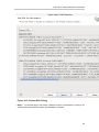
The vdb.xml file example below highlights the basic model information.
Note
The VIRTUAL and PHYSICAL <model> elements containing property references
to the INDEX files as well as the <source> element info for the PHYSICAL (aka
source) model EU_CustomerAccounts.xmi.
<?xml version="1.0" encoding="UTF-8" standalone="yes"?>
<vdb version="1" name="Financials">
<model visible="true" type="VIRTUAL" name="US_CustomerAccounts" path="/
Financials/US_CustomerAccounts.xmi">
<property value="4097408696" name="checksum"/>
<property value="Relational" name="modelClass"/>
<property value="false" name="builtIn"/>
<property value="1592679058.INDEX" name="indexName"/>
<property value="/Financials/US_CustomerAccounts.xmi"
name="imports"/>
</model>
<model visible="true" type="PHYSICAL" name="EU_CustomerAccounts" path="/
Financials/EU_CustomerAccounts.xmi">
<property value="525566235" name="checksum"/>
<property value="Relational" name="modelClass"/>
<property value="false" name="builtIn"/>
<property value="1119071590.INDEX" name="indexName"/>
<source translator-name="postgresql" connection-jndiname="EU_CustomerAccounts" name="EU_CustomerAccounts"/>
</model>
</vdb>
Fortunately, Teiid Designer simplifies the management of your VDBs by providing a dedicated
VDB Editor which maintains a consistent, valid vdb.xml file for you and assists in synchronizing
14
Model Validation
your workspace models with any related models in your VDB. (See the Section D.3.2, “VDB Editor”
section)
1.3.7. Model Validation
Models must be in a valid state in order to be used for data access. Validation of a single model
means that it must be in a self-consistent and complete state, meaning that there are no "missing
pieces" and no references to non-existent entities. Validation of multiple models checks that all
inter-model dependencies are present and resolvable.
Models must always be validated when they are deployed in a VDB for data access purposes.
Teiid Designer will automatically validate all models whenever they are saved.
Note
The "Project > Build Automatically" menu option must be checked. When editing
models, the editor tabs will display a "*" to indicate that the model has unsaved
changes.
1.3.8. Testing Your Models
Designing and working with data is often much easier when you can see the information you're
working with. The Teiid Designer's Preview Data feature makes this possible and allows you to
instantly preview the information described by any object, whether it's a physical table or a virtual
view. In other words, you can test the views with actual data by simply selecting the table, view,
procedure or XML document. The preview functionality insures that data access behavior in Teiid
Designer will reliably match when the VDB is deployed to the Server. ( See: ??? for details)
Previewing information is a fast and easy way to sample the data. Of course, to run more
complicated queries like what your application likely uses, simply execute the VDB in Teiid
Designer and type in any query or SQL statement.
After creating your models, you can test them by using the Preview Data action
.
By selecting a desired table object and executing the action, the results of a simple query will
be displayed in the Data Tools SQL Results view. This action is accessible throughout the Teiid
Designer in various view toolbars and context menus.
Previewable objects include:
• Relational table or view, including tables involving access patterns.
• Relational procedure.
• Web Service operation.
15
Chapter 1. Introduction
• XML Document staging table.
Note
If attempting to preview a relational access pattern, a web service operation or a
relational procedure with input parameters, a dialog will request values for required
parameters.
1.3.9. Model Object Extensions
Teiid Designer in conjunction with Teiid provides an extensible framework to define custom
properties for model objects over-and-above what is defined in the metamodel. These custom
property values are added to your VDB and included in your runtime metadata. This additional
metadata is available to use in your custom translators for both source query manipulation as well
as adjusting your result set data being returned.
In the 7.6 release, Teiid Designer introduces a new Model Extension Definition (MED)
framework that will replace the current EMF-based Model Extension metamodel in a later 8.0
release.
This new MED framework provides the following improvements:
• Eliminate need for separate EMF metamodel.
• Simpler approach including reduction of extendable metamodels and metamodel objects
(Relational, Web Services, XML Document, User Defined Functions) and replacing EMF
terminology with basic object types.
• Allows metamodels to be extended by multiple MEDs
• MEDs are stored in models so no added dependency needed in VDB
Also see: Section 5.4, “Managing Model Object Extensions” and Section D.3.3, “Model Extension
Definition Editor”.
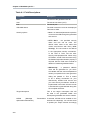
1.3.9.1. Model Extension Definition (MED)
The purpose of a MED is to define one or more sets of extension properties. Each set of extension
properties pertains to one model object type (or metaclass). Each MED consists of the following:
• Namespace Prefix - a unique identifier. Typically only a small number of letters and can be
used as an abbreviation for the namespace URI.
• Namespace URI - a unique URI.
• Extended Metamodel URI (Model Class) - the metamodel URI that is being extended. Each
metamodel URI also has model class and that is typically what is shown in the Designer. The
16
Model Object Extensions
model classes supported for extension are: Relational, Web Service, XML Document, and
Function.
• Version - (currently not being used)
• Description - an optional description or purpose.
• Extended Model Object Types (Metaclasses) - a set of model object types, or metaclasses,
that have extension properties defined.
• Properties - the extension property definitions grouped by model object type.
A MED file is an XML file with an extension of "mxd." A MED schema file (see attached
modelExtension.xsd file) is used to validate a MED file. Here is a sample MED file:
<?xml version="1.0" encoding="UTF-8" standalone="no"?>
<modelExtension xmlns:p="http://org.teiid.modelExtension/2011"
xmlns:xsi="http://www.w3.org/2001/XMLSchema-instance"
metamodelUri="http://www.metamatrix.com/metamodels/Relational"
namespacePrefix="mymodelextension"
namespaceUri="org.my.extension.mymodelextension"
version="1"
xsi:schemaLocation="http://org.teiid.modelExtension/2011
modelExtension.xsd"
xmlns="http://org.teiid.modelExtension/2011">
<p:description>This is my model extension</p:description>
<p:extendedMetaclass
name="com.metamatrix.metamodels.relational.impl.BaseTableImpl">
<p:property advanced="false" index="true" masked="false"
name="copyable" required="false" type="boolean">
<p:description locale="en_US">Indicates if table can be copied</
p:description>
<p:display locale="en_US">Copyable</p:display>
</p:property>
</p:extendedMetaclass>
</modelExtension>
The MED Registry is where the MEDs used by Designer are stored. MED files can be edited by
opening the .mxd file in the Section D.3.3, “Model Extension Definition Editor”.
1.3.9.2. Model Extension Definition Registry (MED Registry)
A MED registry keeps track of all the MEDs that are registered in a workspace. Only registered
MEDs can be used to extend a model. There are 2 different types of MEDs stored in the registry:
• Built-In MED - these are registered during Designer installation. These MEDs cannot be
updated or unregistered by the user.
17
Chapter 1. Introduction
• User-Defined MED - these are created by the user. These MEDs can be updated, registered,
and unregistered by the user.
The MED Registry state is persisted and is restored each time a new session is started.
18
Chapter 2.
Dive Right In!
We are going to dive right into a couple examples of common tasks in this section. These examples
will give you a quick introduction to the capabilities that are built into Designer to assist you with
common design tasks. Specifically, we will introduce the following concepts:
• Targeting the Teiid Server
The Teiid Server is the destination for Designer's modelling. It is essential to define the correct
server version that models will be deployed to. This is achieved either by setting the server
version preference or defining a teiid server in the Servers View.
• Guides
The Guides View is a good starting point for many common modeling tasks. The view
includes categorized Modeling Actions and also links to Cheat Sheets for common tasks.
The categorized Modeling Actions simply group together all of the actions that you'll need to
accomplish a task. You can launch the actions directly from the Guides view, rather than hunting
through the various Designer menus.
• Cheat Sheets
The Cheat Sheets go beyond even the categorized Action Sets, and walk you step-by-step
through some common tasks. At each step, the data entered in the previous step is carried
through the process when possible.
After seeing the Guides and Cheat Sheets in action, subsequent chapters will offer detailed
explanations of the various concepts and actions.
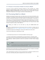
2.1. Targeting the Teiid Server
In this section, the setting of the teiid server version is demonstrated. This can be achieved by
either setting a preference or by defining a teiid server.
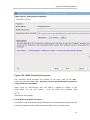
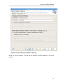
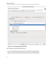
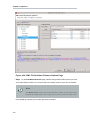
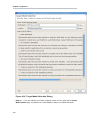
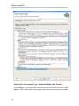
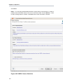
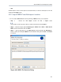
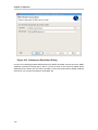
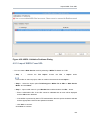
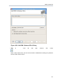
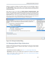
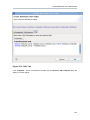
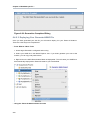
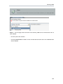
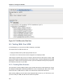
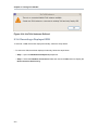
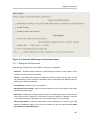
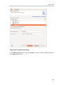
2.1.1. Server Version Preference
The default server version preference allows the target server version to be changed without
actually having to define a teiid server in Designer. The preference's list of possible values is
determined by which teiid runtime client plugins have been installed into the application.
19
Chapter 2. Dive Right In!
Figure 2.1. Default Server Version Preference
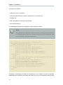
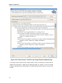
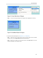
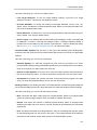
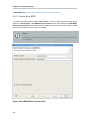
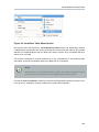
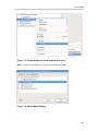
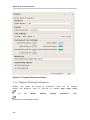
2.1.2. Defining a Teiid Server
The defining of a Teiid Server is encouraged since it allows for models to be previewed and their
deployment tested. There is no limit to the number of servers that can be defined. However, the
default server will always be used for previewing and deployment, unless using the context menu
actions in the Section D.2.3, “Server View”.
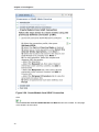
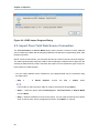
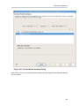
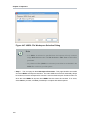
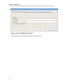
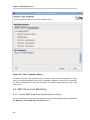
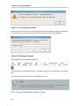
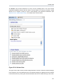
The Guides View provides the following Teiid Server actions.
20
Server Version Status Panel
Figure 2.2. Teiid Server Category in the Guides View
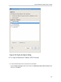
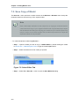
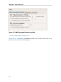
The New Teiid Server action will display the wizard outlined in Figure D.14, “New Teiid Instance
Dialog” and steps through the process of creating both the Teiid Server and its parent JBoss
server in the Server View.
Should more than one Teiid Server be defined in the Server View then the Set the Default Server
action allows for the default server to be changed appropriately. If a Teiid Server is currently
selected in the Server View then this will be selected as the default server. However, should
nothing be selected then a dialog will be displayed inviting the user to choose which server they
wish to select.
Note
The version of the defined Teiid server always takes precedence over the
Section 2.1.1, “Server Version Preference”
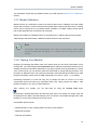
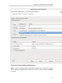
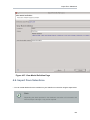
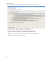
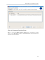
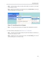
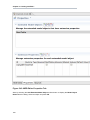
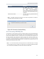
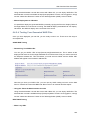
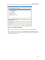
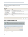
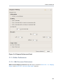
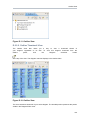
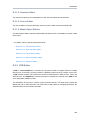
2.1.3. Server Version Status Panel
Whether the server version preference has been modified or a server defined, the server and
server target version will be updated in the default server status panel. This will always reflect the
current server version being targeted and the server being used to preview or deploy against.
21
Chapter 2. Dive Right In!
Figure 2.3. Default Server Status Panel
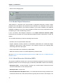
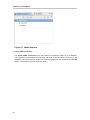
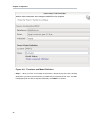
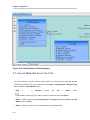
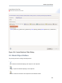
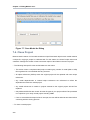
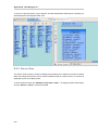
2.2. Guide Example
In this section, the Guides View is demonstrated in detail by walking through a simple example.
For this example, we will follow the Model JDBC Source Action Set. The actions appear in the
following order:
1. Define Teiid Model Project
2. Create JDBC connection
3. Create source model for JDBC data source
4. Preview Data
5. Define VDB
6. Execute VDB
The action names are self explanatory. We will create a new "Model Project" in the workspace,
then define our connection properties to a MySQL database. We will then connect to the database
and import the 'metadata', creating a source model in Designer. Next we will 'preview' the database
contents. Finally we will define a 'VDB' and then deploy it to a running Teiid Server to execute.
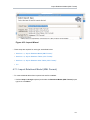
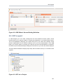
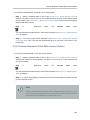
2.2.1. Model a JDBC Source
This section shows how to Model a JDBC Source, using the Guide View action set. We will connect
to a MySQL database for this example, but you can use the same process to connect to any
supported database.
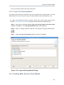
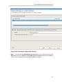
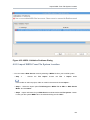
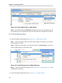
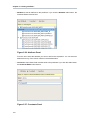
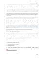
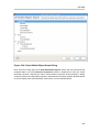
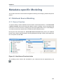
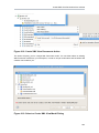
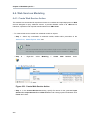
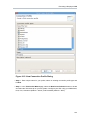
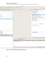
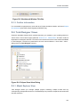
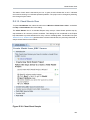
1. Open Guides View
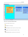
To open the Teiid Designer's Guides view, select the main menu's Window > Show View >
Other... and select the Teiid Designer > Guides view in the dialog.
The Guides view is shown below, with the Model JDBC Source Action Set selected:
22
Model a JDBC Source
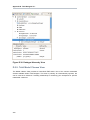
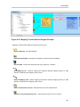
Figure 2.4. Guides View
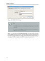
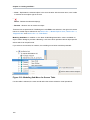
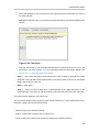
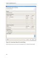
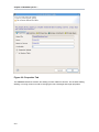
2. Define Teiid Model Project
The Define Teiid Model Project action launches the New Model Project Wizard. In the Action
Set list, double-click the action (or select it, then click 'Execute selected action'). The wizard
is launched as shown below:
23
Chapter 2. Dive Right In!
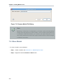
Figure 2.5. New Project Wizard
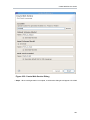
Enter a project name, e.g. 'MyProject' for the name. Then click Next. The next page of the
wizard is shown below:
24
Model a JDBC Source
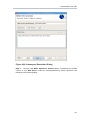
Figure 2.6. New Project Folders
Under 'Create Folders', de-select 'schemas' and 'web_services' - we won't need them for this
example. Now, click Finish to exit the wizard. The project has now been created - your Model
Explorer view should like like this:
25
Chapter 2. Dive Right In!
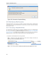
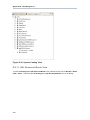
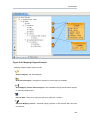
Figure 2.7. Model Explorer
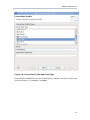
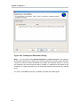
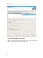
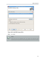
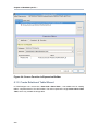
3. Create JDBC connection
The Create JDBC connection action will create the 'Connection profile' for your database.
The connection profile defines the properties and driver to be used when connecting to the
database. In the Action Set list, double-click the action (or select it, then click 'Execute selected
action'). The wizard is launched as shown below:
26
Model a JDBC Source
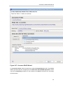
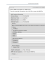
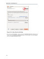
Figure 2.8. Connection Profile Name and Type
Select the type of database that you are connecting to (e.g. MySQL), and enter a name for the
connection profile, e.g. 'TestMySQL'. Click Next.
27
Chapter 2. Dive Right In!
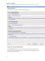
Figure 2.9. Connection Profile properties
Now, select the driver and enter the login properties for your database. Click Finish to complete
the profile creation.
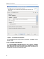
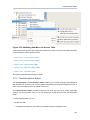
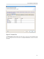
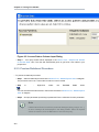
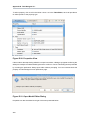
4. Create source model for JDBC data source
The Create source model for JDBC data source action will now utilitze the Connection
profile that you just created, to import the metadata from the database to create your Teiid
Source Model. In the Action Set list, double-click the action (or select it, then click 'Execute
selected action'). The wizard is launched as shown below:
28
Model a JDBC Source
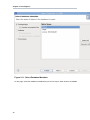
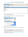
Figure 2.10. Select Connection Profile
On this page, select the 'TestMySQL' Connection profile that you created in the previous step.
Click Next.
29
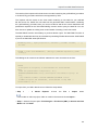
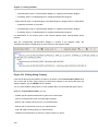
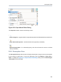
Chapter 2. Dive Right In!
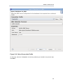
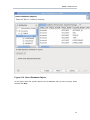
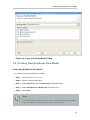
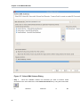
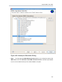
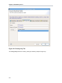
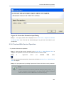
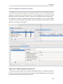
Figure 2.11. Select Database Metadata
On this page, select the database metadata that you want to import. When finished, click Next.
30
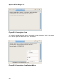
Model a JDBC Source
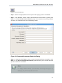
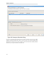
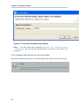
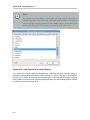
Figure 2.12. Select Database Objects
On this page, select the specific objects from the database that you want to import. When
finished, click Next.
31
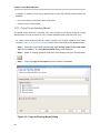
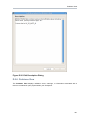
Chapter 2. Dive Right In!
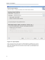
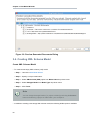
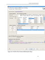
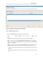
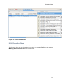
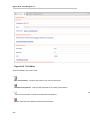
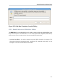
Figure 2.13. Import Options
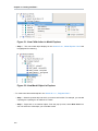
Finally, choose the name for the model to be created (defaults to 'profileName'.xmi). The 'Into
Folder' field defines the target location for your new model. Select the 'MyProject/sources'
folder. Now, click Finish. The source model has now been created - your Model Explorer view
should like like this:
32
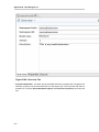
Model a JDBC Source
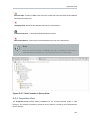
Figure 2.14. Model Explorer
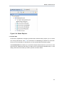
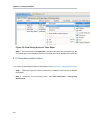
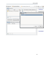
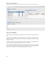
5. Preview Data
All execution capabilities in Designer (Preview Data, VDB execution) require you to connect
to a running Teiid Server. See ??? for instructions on establishing a Teiid Server connection.
Once you are connected to a Teiid Server, you can proceed with the following steps.
The Preview Data action allows you to preview a sample of data rows from your source. In the
Action Set list, double-click the action (or select it, then click 'Execute selected action'). In the
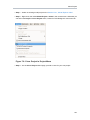
dialog, select the source table you want to preview, as shown below:
33
Chapter 2. Dive Right In!
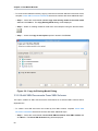
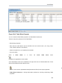
Figure 2.15. Select Preview Table
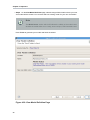
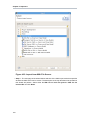
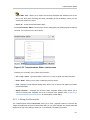
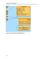
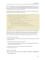
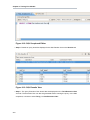
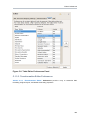
After selecting the table, click OK. Now, the preview results will be displayed:
Figure 2.16. Preview Results
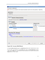
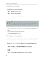
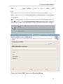
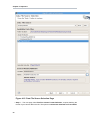
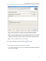
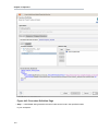
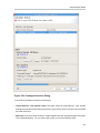
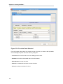
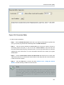
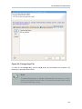
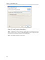
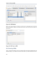
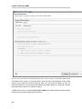
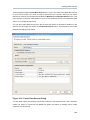
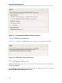
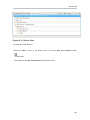
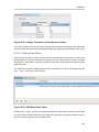
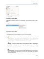
6. Define VDB
The Define VDB action allows you to create a VDB (Virtual Database) artifact for deployment
to a Teiid Server. In the Action Set list, double-click the action (or select it, then click 'Execute
selected action'). The following dialog is displayed:
34
Model a JDBC Source
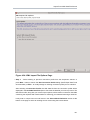
Figure 2.17. New VDB
In the dialog, select the target 'In Folder' location where the VDB will be placed. Enter a Name
for the VDB, for example 'myVDB'. Finally, select the models that will be included in the VDB.
When finished, click Finish. The VDB will be created in your Teiid Model Project - as shown
in the following figure.
35
Chapter 2. Dive Right In!
Figure 2.18. Model Explorer
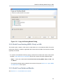
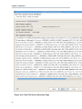
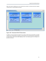
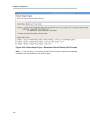
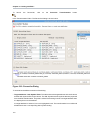
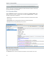
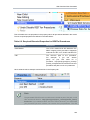
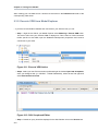
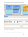
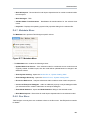
7. Execute VDB
Finally, the Execute VDB action allows you to execute your VDB and run sample queries
against it. In the Action Set list, double-click the action (or select it, then click 'Execute selected
action'). In the dialog, select the VDB you want to execute, then click OK. The VDB will
be deployed and executed, and the perpective will switch to the 'Database Development'
perspective. You can now run queries against the VDB, as show in the following example:
36
Cheat Sheet Example
Figure 2.19. Execute VDB Example
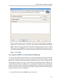
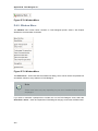
2.3. Cheat Sheet Example
In this section, we introduce Cheat Sheets by walking through a simple example. For this example,
we will follow the Consume a SOAP Web Service Cheat Sheet.
2.3.1. Consume a SOAP Web Service
This section shows how to consume a SOAP Web Service, using a Cheat Sheet. We will
demonstrate connection to a publicly accessible web service. You can use this process as an
example for modeling other web services
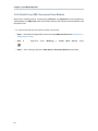
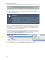
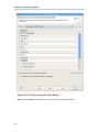
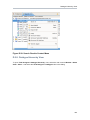
1. Open the Cheat Sheet
You can access the Cheat Sheet from the Designer Menu. From the Designer main menu,
select Window > Show View > Other..., then select Help > Cheat Sheets in the dialog.
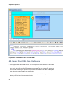
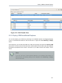
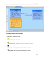
Alternately, you can access the Cheat Sheet from the Guide View. A sample Guide view is
shown below, with the Consume a SOAP Web Service Action Set selected:
37
Chapter 2. Dive Right In!
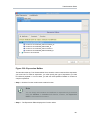
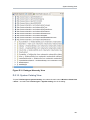
Figure 2.20. Guides View
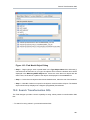
To open the Cheat Sheet from the Guide View, expand the Cheat Sheet section in the lower
portion of the Guide View, then select the Consume a SOAP Web Service link.
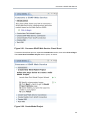
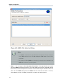
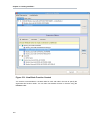
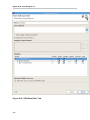
2. Begin the Cheat Sheet
The Consume a SOAP Web Service Cheat Sheet is shown below:
38
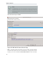
Consume a SOAP Web Service
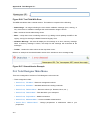
Figure 2.21. Consume SOAP Web Service Cheat Sheet
To start the Cheat Sheet process, expand the Introduction section, then select Click to Begin.
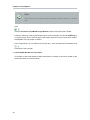
The Create New Teiid Model Project section opens, as shown.
Figure 2.22. Create Model Project
39
Chapter 2. Dive Right In!
Note
Each section of the sheet has basic instructions outlining what to do at each
step.
Click
next to Launch New Teiid Model Project Wizard to launch the 'New Project' wizard.
Follow the wizard to create a new Model Project. For this example, we will use SOAPProj for
our project name. On the second page of the wizard, select the 'sources' and 'views' folders.
Click Finish. The new project is created.
In the Cheat Sheet, you can advance to the next step - once the wizard has completed. Click
to advance to the next step.
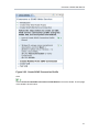
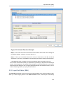
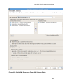
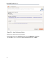
3. Create SOAP Web Service Connection
This section of the Cheat Sheet provides instructions for creating a connection profile for the
SOAP Web Service, as shown below:
40
Consume a SOAP Web Service
Figure 2.23. Create SOAP Connection Profile
Click
next to Launch Create SOAP Connection Profile Wizard to launch the wizard. The first page
of the wizard is shown below:
41
Chapter 2. Dive Right In!
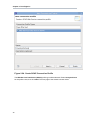
Figure 2.24. Create SOAP Connection Profile
The Web Services Data Source (SOAP) profile type will be selected. Enter CountryInfoConn
for the profile name, then click Next. The next page of the wizard is shown below:
42
Consume a SOAP Web Service
Figure 2.25. SOAP Connection Properties
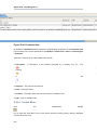
The connection profile properties are entered on this page. Click on the URL...
button, then enter the following URL: http://www.oorsprong.org/websamples.countryinfo/
CountryInfoService.wso?WSDL
Select 'None' for SecurityType, then click OK to complete the wizard. In the
Cheat Sheet, you can now continue - once the wizard has completed. Click
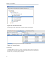
to advance to the next step.
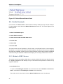
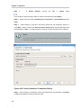
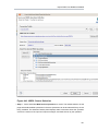
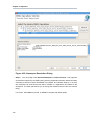
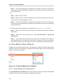
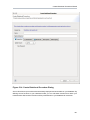
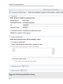
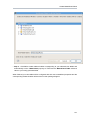
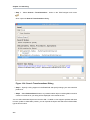
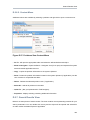
4. Create Models from SOAP Connection
This section of the Cheat Sheet provides instructions for creating relational models using the
previously-created connection profile for the SOAP Web Service, as shown below:
43
Chapter 2. Dive Right In!
Figure 2.26. Create Models from SOAP Connection
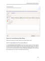
Click
next to Launch the Consume SOAP Web Service Wizard to launch the wizard. The first page
of the wizard is shown below:
44
Consume a SOAP Web Service
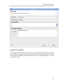
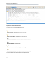
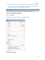
Figure 2.27. Consume SOAP Wizard
For Connection Profile, select the previously-created CountryInfoConn profile. The available
WSDL Operations will then be displayed under Select the desired WSDL Operations. Select
only the first CapitalCity Operation for this example. Click Next to proceed to the next page,
as shown below:
45
Chapter 2. Dive Right In!
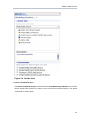
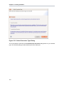
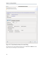
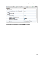
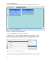
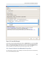
Figure 2.28. Consume SOAP Wizard
On the Model Definition page, the source and view model info section will be pre-filled. We will
keep the names and location defaults for the source and view models. Click Next to proceed
to the next page, as shown below:
46
Consume a SOAP Web Service
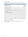
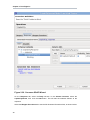
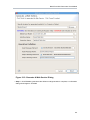
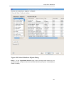
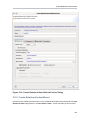
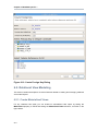
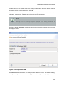
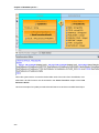
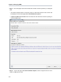
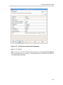
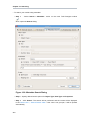
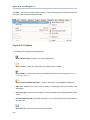
Figure 2.29. Consume SOAP Wizard
On the Procedure Definition page, the CapitalCity Operation will be selected since it is the
only one used for this example. On the Request tab, select the sCountryISOCode element
- then click the Add button. This will add the selected element to the request. Now select the
Response tab, as shown below:
47
Chapter 2. Dive Right In!
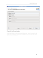
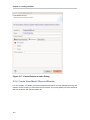
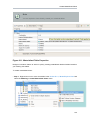
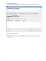
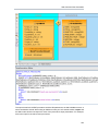
Figure 2.30. Consume SOAP Wizard
On the Response tab, select the Body sub-tab. In the Schema Contents, select the
CapitalCityResult, then click the Add button. This will add the selected element to the
response.
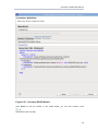
Select the Wrapper Procedure tab to see the full Generated Procedure SQL, as shown below.
48
Consume a SOAP Web Service
Figure 2.31. Consume SOAP Wizard
Click Finish to exit the wizard. In the Cheat Sheet, you can now continue. Click
to advance to the next step.
49
Chapter 2. Dive Right In!
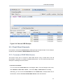
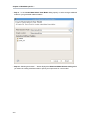
5. Create VDB
This section of the Cheat Sheet provides instructions for creating a VDB using the models that
you created in the previous step. The Cheat Sheet section is shown below:
Figure 2.32. Create VDB
Click
next to Launch New VDB Wizard to launch the wizard. Follow the steps to create a VDB in your
workspace. When complete, exit the wizard. In the Cheat Sheet, you can now continue. Click
to advance to the next step.
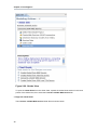
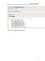
6. Test VDB
This
for
final
section
executing
the
of
VDB
the
Cheat
created
in
Sheet
the
provides
instructions
previous
step.
Click
next to Launch Execute VDB Dialog to launch the wizard. Select the previously-created VDB
to execute it.
50
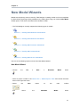
Chapter 3.
New Model Wizards
Models are the primary resource used by Teiid Designer. Creating models can be accomplished
by either directly importing existing metadata or by creating them using one of several New Model
wizard options. This section describes these wizards in detail.
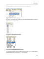
• The Teiid Designer currently supports the following types of models:
•
Section 3.1, “Creating New Relational Source Model”
•
Section 3.2, “Creating New Relational View Model”
•
Section 3.3, “Creating XML Document View Model”
•
Section 3.4, “Creating XML Schema Model”
•
Section 3.5, “Creating Web Service View Model”
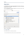
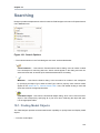
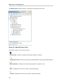
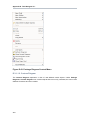
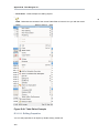
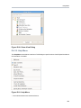
Use one of the following options to launch the New Model Wizard.
New Model Wizard
• Choose
the
File
>
New...
>
Metadata
Model
action
.
• Select a project or folder in the Section D.2.1, “Model Explorer View” and choose the same
action in the right-click menu.
• Select
and
the
select
New
button
the
on
Metadata
the
main
Model
toolbar
action
.
51
Chapter 3. New Model Wizards
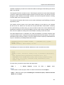
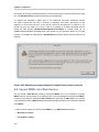
Note
Model names are required to be unique within Designer. When specifying model
names in new model wizards and dialogues error messages will be presented and
you will prevented from entering an existing name.
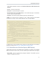
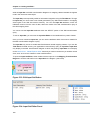
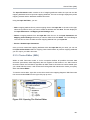
Figure 3.1. Import Wizard Selection Dialog
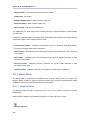
3.1. Creating New Relational Source Model
Create New Relational Source Model
• To create a new empty relational source model:
• Step 1 - Launch the New Model Wizard.
52
Generate File Translator Procedures
• Step 2 - Specify a unique model name.
• Step 3 - Select Relational option from Model Class drop-down menu.
• Step 4 - Select Source Model from Model Type drop-down menu.
• Step 5 - Click Finish.
Note
You can change the target location (i.e. project or folder) by selecting the Browse...
button and selecting a project or folder within your workspace.
• In addition to creating a new empty relational source model, the following builder options are
available:
• Copy from existing model of the same model class.
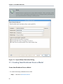
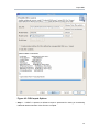
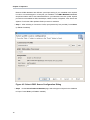
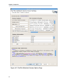
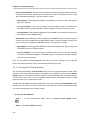
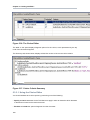
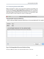
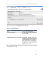
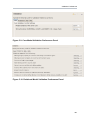
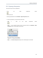
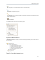
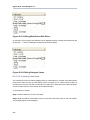
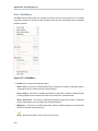
3.1.1. Generate File Translator Procedures
This builder option allows construction of a relational model containing one or more of the
procedures required for accessing file-based data via a file translator.
• To create a new relational model containing file translator procedures, complete Create New
Relational Source Model above and continue with these additional steps:
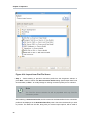
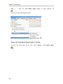
• Step 5 - Select the model builder labeled Generate File Translator Procedures and click
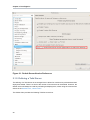
Next >. The Generate File Translator Procedures dialog will be displayed.
• Step 6 - Check one ore more of the Available File Translator Procedures, then Click Finish
53
Chapter 3. New Model Wizards
Figure 3.2. Generate File Translator Procedures Dialog
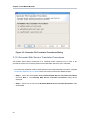
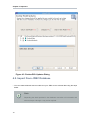
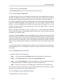
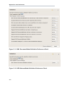
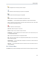
3.1.2. Generate Web Service Translator Procedures
This builder option allows construction of a relational model containing one or more of the
procedures required for accessing web-service-based XML data via a web s translator.
• To create a new relational model containing web-service-based translator procedures, complete
Create New Relational Source Model above and continue with these additional steps:
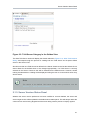
• Step 5 - Select the model builder labeled Generate Web Service Translator Procedures
and click Next >. The Generate Web Service Translator Procedures dialog will be
displayed.
• Step 6 - Check one ore more of the Available Web Services Translator Procedures, then
Click Finish
54
Generate Web Service Translator Procedures
Figure 3.3. Generate Web Service Translator Procedures Dialog
55
Chapter 3. New Model Wizards
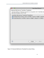
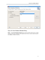
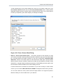
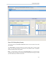
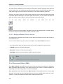
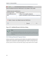
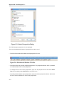
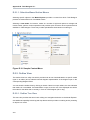
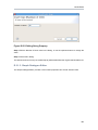
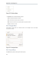
3.1.3. Copy From Existing Model
This builder option performs a structural copy of the contents of an existing model to a newly
defined model. You can choose a full copy or select individual model components for copy.
• To create a new relational model by copying contents from another relational source model,
complete Create New Relational Source Model above and continue with these additional steps:
• Step 5 - Select the model builder labeled Copy from existing model of the same model
class and click Next >. The Copy Existing Model dialog will be displayed.
• Step 6 - Select an existing relational model from the workspace using the browse button.
Note
An existing model will be pre-selected if a relational model in the workspace is
selected in the Section D.2.1, “Model Explorer View” prior to starting the new
model wizard.
• Step 7 - Check the Copy all descriptions option if desired. Click Finish
56
Creating New Relational View Model
Figure 3.4. Copy An Existing Model Dialog
3.2. Creating New Relational View Model
Create New Relational View Model
• To create a new empty relational view model:
• Step 1 - Launch the New Model Wizard.
• Step 2 - Specify a unique model name.
• Step 3 - Select Relational option from Model Class drop-down menu.
• Step 4 - Select View Model from Model Type drop-down menu.
• Step 5 - Click Finish.
Note
You can change the target location (i.e. project or folder) by selecting the Browse...
button and selecting a project or folder within your workspace.
57
Chapter 3. New Model Wizards
• In addition to creating a new empty relational view model, the following builder options are
available:
• Copy from existing model of the same model class.
• Transform from existing model.
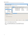
3.2.1. Copy From Existing Model
This builder option performs a structural copy of the contents of an existing model to a newly
defined model. You can choose a full copy or select individual model components for copy.
• To create a new relational model by copying contents from another relational view model,
complete Create New Relational View Model above and continue with these additional steps:
• Step 5 - Select the model builder labeled Copy from existing model of the same model
class and click Next >. The Copy Existing Model dialog will be displayed.
• Step 6 - Select an existing relational model from the workspace using the browse button.
• Step 7 - Check the Copy all descriptions option if desired. Click Finish
Figure 3.5. Copy An Existing Model Dialog
58
Transform From Existing Model
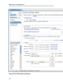
3.2.2. Transform From Existing Model
This option is only applicable for creating a relational view model from a relational
source model with the added feature of creating default transformations (SELECT * FROM
SourceModel.Table_X) for each source table. The steps are the same as for the Section 3.2.1,
“Copy From Existing Model” described above.
There is an additional option in the second page of the wizard which can automatically set the
relational table's supports update property to false. If this is unchecked the default value will be
true.
3.3. Creating XML Document View Model
Create XML Document View Model
• To create a new empty XML document view model:
• Step 1 - Launch the New Model Wizard.
• Step 2 - Specify a unique model name.
• Step 3 - Select XML option from Model Class drop-down menu.
• Step 4 - Select View Model from Model Type drop-down menu.
• Step 5 - Click Finish.
Note
You can change the target location (i.e. project or folder) by selecting the Browse...
button and selecting a project or folder within your workspace.
• In addition to creating a new empty XML document view model, the following builder options
are available:
• Copy from existing model of the same model class.
• Build XML documents from XML schema.
3.3.1. Copy From Existing Model
This builder option performs a structural copy of the contents of an existing model to a newly
defined model. You can choose a full copy or select individual model components for copy.
59
Chapter 3. New Model Wizards
• To create a new relational model by copying contents from another XML document view model,
complete Create XML Document View Model above and continue with these additional steps:
• Step 5 - Select the model builder labeled Copy from existing model of the same model
class and click Next >. The Copy Existing Model dialog will be displayed.
• Step 6 - Select an existing relational model from the workspace using the browse button.
• Step 7 - Check the Copy all descriptions option if desired. Click Finish
Figure 3.6. Copy An Existing Model Dialog
3.3.2. Build XML Documents From XML Schema
This option creates an XML View document model based on a selected XML schema and its
dependencies.
• To create a new XML document view model by from XML schema, complete Create XML
Document View Model above and continue with these additional steps:
• Step 5 - Select the model builder labeled Build XML documents from XML schema and
click Next >. The Select XML Schema dialog will be displayed.
60
Build XML Documents From XML Schema
• Step 6 - Select an existing schema model from the workspace using the browse button.
Note
An existing model will be pre-selected if an XSD model in the workspace
is selected in the VDB explorer prior to starting the new model wizard. The
schema must be found in the workspace so if you need to get one or more
into the workspace use the XSD Schemas on file system importer.
61
Chapter 3. New Model Wizards
Figure 3.7. Select XML Schema Dialog
• Step 7 - Move the available schema root elements you want to become virtual
documents in the new model over to the Virtual Documents list by using the arrow button
for
62
selected
elements
or
the
Build XML Documents From XML Schema
button to move all elements.
• Step 8 - Select the appropriate document options and mapping options. Click Finish
• Step 9 - Click Finish to create a model of all selected document entities or (optional) click
Next > to view Selected Documents Statistics page which shows document entity statistics
and gives you an idea the size of the model being created.
Figure 3.8. Selected Documents Statistics Dialog
• Step 10 - (Optional) Click Finish to create a model of all selected document entities or click
Next > to view Preview Generated Documents page that allows you to exclude document
specific entities then click Finish.
Note
For deeply nested schema, your total entity count may be large. If so,
displaying the preview may take some time.
63
Chapter 3. New Model Wizards
Figure 3.9. Preview Generated Documents Dialog
3.4. Creating XML Schema Model
Create XML Schema Model
• To create a new empty XML schema (.xsd) model:
• Step 1 - Launch the New Model Wizard.
• Step 2 - Specify a unique model name.
• Step 3 - Select XML Schema (XSD) option from Model Class drop-down menu.
• Step 4 - Select Datatype Model from Model Type drop-down menu.
• Step 5 - Click Finish.
Note
You can change the target location (i.e. project or folder) by selecting the Browse...
button and selecting a project or folder within your workspace.
• In addition to creating a new empty XML schema model, the following builder option is available:
64
Copy From Existing Model
• Copy from existing model of the same model class.
3.4.1. Copy From Existing Model
This builder option performs a structural copy of the contents of an existing model to a newly
defined model. You can choose a full copy or select individual model components for copy.
• To create a new relational model by copying contents from another XML schema model,
complete Create XML Schema Model above and continue with these additional steps:
• Step 5 - Select the model builder labeled Copy from existing model of the same model
class and click Next >. The Copy Existing Model dialog will be displayed.
• Step 6 - Select an existing relational model from the workspace using the browse button.
• Step 7 - Check the Copy all descriptions option if desired. Click Finish
Figure 3.10. Copy An Existing Model Dialog
3.5. Creating Web Service View Model
65
Chapter 3. New Model Wizards
Create Web Service View Model
• To create a new empty web service view model:
• Step 1 - Launch the New Model Wizard.
• Step 2 - Specify a unique model name.
• Step 3 - Select Web Service option from Model Class drop-down menu.
• Step 4 - Select View Model from Model Type drop-down menu.
• Step 5 - Click Finish.
Note
You can change the target location (i.e. project or folder) by selecting the Browse...
button and selecting a project or folder within your workspace.
• In addition to creating a new empty web service view model, the following builder options are
available:
• Copy from existing model of the same model class.
• Build from existing WSDL file(s) or URL.
3.5.1. Copy From Existing Model
This builder option performs a structural copy of the contents of an existing model to a newly
defined model. You can choose a full copy or select individual model components for copy.
• To create a new relational model by copying contents from another web service view model,
complete Create Web Service View Model above and continue with these additional steps:
• Step 5 - Select the model builder labeled Copy from existing model of the same model
class and click Next >. The Copy Existing Model dialog will be displayed.
• Step 6 - Select an existing relational model from the workspace using the browse button.
• Step 7 - Check the Copy all descriptions option if desired. Click Finish
66
Build From Existing WSDL File(s) or URL
Figure 3.11. Copy An Existing Model Dialog
3.5.2. Build From Existing WSDL File(s) or URL
This builder option creates a Web service model based on a user-defined WSDL file and its
referenced schemas. In addition, applicable XML schema files and XML View document models
(optional) are created.
• To create a new relational model by copying contents from another web service view model,
complete Create Web Service View Model above and continue with these additional steps:
• Step 5 - Select the model builder labeled Build from existing WSDL file(s) or URL and
click Next >.
• The remaining wizard steps are identical to those found using the Section 4.9, “Import WSDL
Into Web Service” action option.
3.5.3. Build From Relational Models
See Section 6.4.1, “Create Web Service Action”
67
Chapter 3. New Model Wizards
3.5.4. Build From XML Document View Models
Web Service models and their corresponding Interfaces and Operations can be generated in
Teiid Designer from XML View model components. Namely, XML View Documents and XML View
Document roots.
• To create a new Web service model from XML components::
• Step 1 - Select either a single XML Document or single XML Document root in Section D.2.1,
“Model Explorer View”.
• Step
2
-
Right-click
select
Modeling
>
Create
Web
Service
• Step 3 - Fill in missing properties in Web Service Generation Wizard shown below.
68
action
Build From XML Document View Models
Figure 3.12. Generate A Web Service Dialog
• Step 4 - Click Finish to generate model. When model generation is complete, a confirmation
dialog should appear. Click OK.
69
Chapter 3. New Model Wizards
Figure 3.13. Generation Completed Dialog
Note
Users can change the Web Service Model and Interface Name values (via "..."
buttons) to use existing Web service model components. This will create a new
operation in an existing model.
70
Chapter 4.
Importers
The Import Wizard provides a means to create a model based on the structure of a data source,
to convert existing metadata (i.e. WSDL or XML Schema) into a source model or to load existing
metadata files into the current VDB.
To launch the Import Wizard, choose the File > Import action or select a project, folder or model
in the tree and right-click choose "Import..."
Figure 4.1. Import Wizard
4.1. Import DDL
Source relational models can be created by importing DDL.
• You can create relational source models from your DDL using the steps below.
71
Chapter 4. Importers
• Step
1
-
In
Model
Explorer
choose
the
File
>
Import
action
in the toolbar or select a project, folder or model in the tree and choose Import...
• Step 2 - Select the import option Teiid Designer > DDL File >> Source or View Model
and click Next>
• Step 3 - Select existing DDL from either Choose from file system... or Choose from
workspace.... set the Model folder location, enter or select valid model name, set Model type
(Source Model or View Model), set desired options and click NEXT> (or Finish if enabled)
72
Import DDL
Figure 4.2. DDL Import Options
• Step 4 - If NEXT> is pressed, a difference report is presented for viewing or de-selecting
individual relational entities. Press Finish to complete.
73
Chapter 4. Importers
Figure 4.3. Review DDL Updates Dialog
4.2. Import From JDBC Database
• You can create relational source models from your JDBC source schema data using the steps
below.
Note
Depending the detail provided in the database connection url information and
schema, Steps 5 through 7 may not be required.
74
Import From JDBC Database
• Step
1
-
In
Model
Explorer
choose
the
File
>
Import
action
in the toolbar or select a project, folder or model in the tree and choose Import...
• Step 2 - Select the import option Metadata Modeling > JDBC Database >> Source Model
and click Next>
• Step 3 - Select existing or previous connection profile from the drop-down selector or
press New... button to launch the New Connection Profile dialog (See Eclispe Data Tools
documentation) or Edit... to modify/change an existing connection profile prior to selection.
Note
the Connection Profile selection list will be populated with only JDBC Database
connections.
Figure 4.4. Select JDBC Source Configuration Dialog
75
Chapter 4. Importers
Because JDBC databases are different, special processing of your metadata to be required
in order to convert datatypes or to interpret your metadata. The JDBC Metadata Processor
drop-down selector will be auto-selected based on your selected connection profile. Special
processors are available for DB2, Modeshape, ODBC, Oracle, PostgeSQL, SQL Server and
Sybase. For all other DB's ajdefault JDBC processor is available.
• Step 4 - After selecting a Connection Profile, input password (if not provided). Press Next>
(or Finish if enabled)
Figure 4.5. Select JDBC Source Configuration Dialog
• Step 5 - On the Select Database Metadata page, select the types of objects in the database
to import. Press Next> (or Finish if enabled).
76
Import From JDBC Database
Figure 4.6. Select Database Metadata Dialog
• Step 6 - On the Select Database Objects page, view the contents of the schema, or change
selections. Select which database schema objects will be used to construct relational objects.
Press Next> (or Finish if enabled)
77
Chapter 4. Importers
Figure 4.7. Select Database Options Dialog
• Step 7 - On the Specify Import Options page, specify desired Model Name as well as
any other options used to customize the naming of your relational objects. Press Finish to
complete.
78
Import From JDBC Database
Figure 4.8. Specify Import Options Dialog
During the Finish processing, a monitor will be displayed providing feedback on the import
progress.
79
Chapter 4. Importers
Figure 4.9. JDBC Import Progress Dialog
4.3. Import From Teiid Data Source Connection
The Teiid Connection >> Source Model import option provides a means to create relational
source models from JDBC and other deployed data sources that are not supported by other Teiid
Designer importers.
NOTE: To launch this importer, you must have at minimum a Teiid 8.x server running in Designer.
The Teiid importer deploys a dynamic VDB to Teiid containing the selected source type, then the
schema (as determined by Teiid) is retrieved. We expect to move towards this type of import in
future versions of Teiid Designer.
• You can create relational source models from your deployed data source connections using
the steps below.
• Step
1
-
In
Model
Explorer
choose
the
File
>
Import
action
in the toolbar or select a project, folder or model in the tree and choose Import...
• Step 2 - Select the import option Teiid Designer > Teiid Connection >> Source Model
and click Next>
• Step 3 - Select the datasource to use for the import. You can create a new source if it doesnt
exist, as well as other source management functions. Click NEXT> to continue.
80
Import From Teiid Data Source Connection
Figure 4.10. Select Deployed Data Source
• Step 4 - On the next page select the appropriate translator for your data source type as
well as defined the target relational model that you wish to create or update. Click NEXT>
to continue.
81
Chapter 4. Importers
Figure 4.11. Translator and Model Definition
• Step 5 - When you move to next page of the wizard, a temporary dynamic vdb is actually
deployed to you rserver and the schema your data source is retrieved in DDL form. This DDL
is displayed (and can also be exported if desired). Click NEXT> to continue.
82
Import From Teiid Data Source Connection
Figure 4.12. Review DDL Dialog
• Step 6 - On the final page of the wizard, a difference report is presented for viewing or deselecting individual relational entities. Press Finish to complete.
83
Chapter 4. Importers
Figure 4.13. Review Model Updates Dialog
4.4. Import From Flat File Source
• You can import metadata from your flat file data sources and create the metamodels required
to query your data in minutes. Using the steps below you will define your flat file data source,
configure your parsing paramaters for the flat file, generate a source model containing the
84
Import From Flat File Source
standard Teiid flat file procedure and create view tables containing the SQL defining the column
data in your flat file.
Teiid supports Flat Files as data sources. Teiid Designer provides an Import wizard designed
to assist in creating the metadata models required to access the data in your flat files. As with
Designer's JDBC, Salesforce and WSDL importers, the Flat File importer is based on utilizing
a specific Data Tools Connection Profile.
The results of the importer will include a source model containing the getTextFiles() procedures
supported by Teiid.
The importer will also create a new view model containing a view table for your selected
flat file source file. Within the view table will be generated SQL transformation containing
the "getTextFiles()" procedure from your source model as well as the column definitions and
parameters required for the Teiid TEXTTABLE() function used to query the data file. You can
also choose to update an existing view model instead of creating a new view model.
The TEXTTABLE function, as defined in the Teiid documentation, processes character input
to produce tabular ouptut. It supports both fixed and delimited file format parsing. The function
itself defines what columns it projects. The TEXTTABLE function is implicitly a nested table and
may be correlated to preceeding FROM clause entries.
TEXTTABLE(expression COLUMNS <COLUMN>, ... [DELIMITER char] [(QUOTE|
ESCAPE) char]
[HEADER [integer]] [SKIP integer]) AS name
Teiid Designer will construct the full SQL statement for each view table in the form:
SELECT
A.Name, A.Sport, A.Position, A.Team, A.City, A.StateCode, A.AnnualSalary
FROM
(EXEC PlayerDataSource.getTextFiles('PlayerData.txt')) AS f,
TEXTTABLE(f.file COLUMNS Name string, Sport string, Position string,
Team string, City string, StateCode string, AnnualSalary string
HEADER 2 SKIP 3) AS A
To import from your flat file source follow the steps below.
• Step
1
-
In
Model
Explorer
choose
the
File
>
Import
action
in the toolbar or select a project, folder or model in the tree and choose Import...
• Step 2 - Select the import option Teiid Designer > File Source (Flat) >> Source and View
Model and click Next>
85
Chapter 4. Importers
Figure 4.14. Import from Flat File Source
• Step 3 - Select existing or previous connection profile from the drop-down selector or
press New... button to launch the New Connection Profile dialog (See Eclispe Data Tools
documentation) or Edit... to modify/change an existing connection profile prior to selection.
Note
The Flat File Source selection list will be populated with only Flat File
connection profiles.
After selecting a Connection Profile, the file contents of the folder defined in the connection
profile will be displayed in the Available Data Files panel. Check the the data file you wish
to process. The data from this file, along with your custom import options, will be used to
86
Import From Flat File Source
construct a view table containing the required SQL transformation for retrieving your data and
returning a result set.
Lastly enter or unique source model name in the Source Model Definition section at the
bottom of the page or select an existing source model using the browse button.
Note
The Model Status section which will indicate the validity of the model name,
whether the model exists or not and whether the model already contains the
getTextFiles() procedure. In this case, the source model nor the procedure
will be generated.
When finished with this page, click Next>.
87
Chapter 4. Importers
Figure 4.15. Data File Source Selection Page
• Step 4 - The next page, titled Flat File Column Format Definition, requires defining the
format of your column data in the file. The options are Character delimited and Fixed width.
88
Import From Flat File Source
This page contains a preview of the contents of your file to aid in determining the format. The
wizard defaults to displaying the first 20 lines, but you can change that value if you wish.
When finished with this page, click Next>.
89
Chapter 4. Importers
Figure 4.16. Data File Source Selection Page
90
Import From Flat File Source
• Step 5a : Character Delimited Option - The primary purpose of this importer is to help
you create a view table containing the transformation required to query the user-defined data
file. This page presents a number of options you can use to customize the Generated SQL
Statement , shown in the bottom panel, for the character delimited option. Specify header
options (Column names in header, header line number and first data line number), Parse
selected row, changed character delimiter and edit the TEXTTABLE() function options. See
the Teiid User's Guide for details on the TEXTTABLE() function.
If columns names are not defined in a file header or if you wish to modify or create custom
columns, you can use the ADD, DELETE, UP, DOWN to manage the column info in your SQL.
When finished with this page, click Next>.
91
Chapter 4. Importers
Figure 4.17. Flat File Delimited Columns Options Page
92
Import From Flat File Source
To aid in determining if your parser settings are correct you can select a data row in your
File Contents Preview section and click the Parse Selected Row button. A dialog will be
displayed showing the list of columns and the resulting column data. If your column data is
not what you expected, you'll need to adjust your settings accordingly.
Figure 4.18. Parse Column Data Dialog
• Step 5b : Fixed Column Width Option - The primary purpose of this importer is to help
you create a view table containing the transformation required to query the user-defined data
file. This page presents a number of options you can use to customize the Generated SQL
Statement , shown in the bottom panel, for the fixed column width option. Specify header
options (Column names in header, header line number and first data line number), Parse
selected row, changed character delimiter and edit the TEXTTABLE() function options. See
the Teiid User's Guide for details on the TEXTTABLE() function.
If columns names are not defined in a file header or if you wish to modify or create custom
columns, you can use the ADD, DELETE, UP, DOWN to manage the column info in your SQL.
You can also utilize the cursor postion and text length values in the upper left panel to
determine what your column widths are in your data file.
93
Chapter 4. Importers
When finished with this page, click Next>.
94
Import From Flat File Source
Figure 4.19. Flat File Fixed Columns Width Options Page
95
Chapter 4. Importers
• Step 6 - On the View Model Definition page, select the target folder location where your new
view model will be created. You can also select an existing model for your new view tables.
Note
The Model Status section which will indicate the validity of the model name,
whether the model exists or not. Lastly, enter a unique, valid view table name.
Press Finish to generate your models and finish the wizard.
Figure 4.20. View Model Definition Page
96
Import From Flat File Source
When your import is finished your source model will be opened in an editor and show a diagram
containing the your getTextFiles() procedure.
Figure 4.21. Generated Flat File Procedures
In addition, the view model will be opened in an editor and will show the generated view tables
containing the completed SQL required to access the data in your flat file using the "getTextFiles"
procedure above and the Teiid TEXTTABLE() function. The following figure is an example of a
generated view table.
97
Chapter 4. Importers
Figure 4.22. Generated Flat File View Table
4.5. Import From XML Data File Source
• Teiid supports XML Files as data sources. You can import from these data sources and create
the metamodels required to query your data in minutes. Using the steps below you will define
your flat file data source, configure your parsing paramaters for the xml data file, generate a
source model containing the required Teiid procedure and create a view table containing the
SQL defining the column data in your xml data file.
As with Designer's JDBC, Salesforce and WSDL importers, the XML File importer is based on
utilizing a specific Data Tools Connection Profile.
98
Import From XML Data File Source
The results of the importer will include a source model containing the getTextFiles() procedure
or invokeHTTP() procedure which are both supported by Teiid.
The importer will also create a new view model containing a view table for your selected
flat file source file. Within the view table will be generated SQL transformation containing
the "getTextFiles()" procedure from your source model as well as the column definitions and
parameters required for the Teiid XMLTABLE() function used to query the data file. You can
also choose to update an existing view model instead of creating a new view model.
The XMLTABLE function uses XQuery to produce tabular ouptut. The XMLTABLE function is
implicitly a nested table and may be correlated to preceeding FROM clause entries. XMLTABLE
is part of the SQL/XML 2006 specification.
XMLTABLE([<NSP>,] xquery-expression [<PASSING>] [COLUMNS <COLUMN>, ... )]
AS name
COLUMN := name (FOR ORDINALITY | (datatype [DEFAULT expression] [PATH
string]))
Teiid Designer will construct the full SQL statement for each view table in the form:
SELECT
A.entryDate AS entryDate, A.internalAudit AS internalAudit
FROM
(EXEC CCC.getTextFiles('sample.xml')) AS f,
XMLTABLE(XMLNAMESPACES('http://www.kaptest.com/schema/1.0/party' AS
pty),
'/pty:students/student' PASSING XMLPARSE(DOCUMENT f.file)
COLUMNS entryDate FOR ORDINALITY, internalAudit string PATH '/
internalAudit') AS A
To import from your XML data file source follow the steps below.
• Step
1
-
In
Model
Explorer
choose
the
File
>
Import
action
in the toolbar or select a project, folder or model in the tree and choose Import...
• Step 2 - Select the import option Teiid Designer > File Source (XML) >> Source and View
Model and click Next>
99
Chapter 4. Importers
Figure 4.23. Import from XML File Source
• Step 3 - The next page of the wizard allows selection of the XML Import mode that specifies
whether the XML file is local or remote. The description at the top describes what operations
this wizard will perform. Select either the XML file on local file system or XML file via
remote URL and click Next>
100
Import From XML Data File Source
Figure 4.24. XML Import File Options Page
• Step 4 - Select existing or previous connection profile from the drop-down selector or
press New... button to launch the New Connection Profile dialog (See Eclispe Data Tools
documentation) or Edit... to modify/change an existing connection profile prior to selection.
After selecting a Connection Profile, the XML data file from the connection profile will be
displayed in the Available Data Files panel. Check the the data file you wish to process. The
data from this file, along with your custom import options, will be used to construct a view table
containing the required SQL transformation for retrieving your data and returning a result set.
Lastly enter or unique source model name in the Source Model Definition section at the
bottom of the page or select an existing source model using the browse button.
101
Chapter 4. Importers
Note
The Model Status section which will indicate the validity of the model name,
whether the model exists or not and whether the model already contains the
getTextFiles() procedure. In this case, the source model nor the procedure
will be generated.
When finished with this page, click Next>.
Figure 4.25. XML Data File Source Selection Page
• Step 5 - The primary purpose of this importer is to help you create a view table containing
the transformation required to query the user-defined data file. This page presents a number
of options you can use to customize the Generated SQL Statement , shown in the bottom
102
Import From XML Data File Source
panel. The to panel contains an XML tree view of your file contents and actions/buttons you
can use to create column entries displayed in the middle, Column Information panel.
To create columns, select a root XML element and right-click select Set as root path action.
This populates the root path value. Next, select columns in the tree that you wish to include
on your query and select Add selection as new column button. You can also modify or
create custom columns, by using the ADD, DELETE, UP, DOWN to manage the column info
in your SQL.
Note
The Path property value for a column is the selected element's path relative
to the defined root path. If no root path is defined all paths are absolute. Each
column entry requires a datatype and an optional default value. See the Teiid
User's Guide for details on the XMLTABLE() function.
When finished with this page, click Next>.
103
Chapter 4. Importers
Figure 4.26. XML File Delimited Columns Options Page
• Step 6 - On the View Model Definition page, select the target folder location where your new
view model will be created. You can also select an existing model for your new view tables.
Note
The Model Status section which will indicate the validity of the model name,
whether the model exists or not. Lastly, enter a unique, valid view table name.
Press Finish to generate your models and finish the wizard.
104
Import From Salesforce
Figure 4.27. View Model Definition Page
4.6. Import From Salesforce
• You can create relational source models from your Salesforce connection using the steps below.
Note
Depending the detail provided in the database connection url information and
schema, Steps 5 through 7 may not be required.
105
Chapter 4. Importers
• Step
1
-
In
Model
Explorer
choose
the
File
>
Import
action
in the toolbar or select a project, folder or model in the tree and choose Import...
• Step 2 - Select the import option Teiid Designer > Salesforce >> Source Model and click
Next>
• Step 3 - Select existing or previous connection profile from the drop-down selector or
press New... button to launch the New Connection Profile dialog (See Eclispe Data Tools
documentation) or Edit... to modify/change an existing connection profile prior to selection.
Note
The Connection Profile selection list will be populated with only Salesforce
connection profiles.
Figure 4.28. Select Salesforce Credentials Dialog
• Step 4 - After selecting a Connection Profile, input password (if not provided). Press Next>
to display the Salesforce Objects selection page.
106
Import From Salesforce
Figure 4.29. Select Salesforce Objects Dialog
• Step 5 - On the Target Model Selection page, specify the target folder location for your
generated model, a unique model name and select desired import options. Press Next> (or
Finish if enabled).
107
Chapter 4. Importers
Figure 4.30. Target Model Selection Dialog
• Step 5a - If you are updating an existing relational model, the next page will be Review
Model Updates page. Any differences. Press Finish to create your models and tables.
108
Import From Salesforce
Figure 4.31. Review Model Updates Dialog
When finished, the new or changed relational model's package diagram will be displayed showing
your new tables.
109
Chapter 4. Importers
Figure 4.32. New Saleforce Tables Diagram
4.7. Import Metadata From Text File
• The Teiid Designer provides various import options for parsing comma delimited text file
metadata into models. This is accomplished via the Import > Teiid Designer > Designer Text
File >> Source or View Models option.
• Step
1
-
In
Designer
choose
the
File
>
Import
action
in the toolbar or select a project, folder or model in the tree and choose Import...
• Step 2 - Select the import option Teiid Designer > Designer Text File >> Source or View
Models and click Next>
• Step 3 - Select an import type via the drop-down menu shown below.
110
Import Relational Model (XML Format)
Figure 4.33. Import Wizard
• These steps are required for each type are defined below:
• Section 4.7.1, “Import Relational Model (XML Format)”
• Section 4.7.2, “Import Relational Tables (CSV Format)”
• Section 4.7.3, “Import Relational View Tables (CSV Format)”
• ???
4.7.1. Import Relational Model (XML Format)
• To create relational tables from imported xml text file metadata:
• Perform Steps 1 through 3 (above) and select the Relational Model (XML Format) import
type, then click Next >
111
Chapter 4. Importers
Figure 4.34. Select Import Type - Relational Model (XML Format)
• Perform Steps 4 - On the next page, select the XML file on your local file system via the
Browse... button. Select a target model to which the imported relational objects will be added
112
Import Relational Model (XML Format)
via the second Browse... button. The dialog allows selecting an existing relational model or
creating a new model.
Note
The contents of your selected XML file will be display in the File Contents
viewer.
Click Finish to create your new model.
113
Chapter 4. Importers
Figure 4.35. Select Source Text File and Target Relational Model Page
If the target model contains named children (tables, views, procedures) that conflict with the
objects being imported, a dialog will be displayed giving you options on how to proceed
including: replacing specific existing objects, creating new same-named objects or cancel import
entirely.
114
Import Relational Tables (CSV Format)
Figure 4.36. Duplicate Objects Dialog
4.7.2. Import Relational Tables (CSV Format)
• To create relational tables from imported text file metadata:
• Perform Steps 1 through 3 (above) and select the Relational Tables (CSV Format) import
type, then click Next >
115
Chapter 4. Importers
Figure 4.37. Select Import Type - Relational Tables (CSV Format)
• Step 4 - In the next page, you'll need to provide a source text file containing the metadata
formatted to the specifications on the previous page.
116
Import Relational View Tables (CSV Format)
Figure 4.38. Select Source Text File and Target Relational Model
• Step 5 - Select an existing relational model as the target location for your new relational
components using the Browse... button to open the Relational Model Selector Dialog. Select
a relational model from your workspace or specify a unique name to create a new model.
• Step 6 - Select any additional options and choose Finish.
4.7.3. Import Relational View Tables (CSV Format)
• To create relational virtual tables from imported text file metadata:
• Perform Steps 1 through 3 (above) and select the Relational Virtual Tables (CSV Format)
import type, then click Next >
117
Chapter 4. Importers
Figure 4.39. Select Import Type - Relational Virtual Tables (CSV Format)
• Step 4 - In the next page, you'll need to provide a source text file containing the metadata
formatted to the specifications on the previous page.
118
Import WSDL into Relational Models
Figure 4.40. Select Source Text File and Target Virtual Relational Model
• Step 5 - Select an existing relational virtual model as the target location for your new model
components using the Browse... button to open the Virtual Model Selector Dialog. Select a
virtual relational model from your workspace or specify a unique name to create a new model.
• Step 6 - Select Finish.
4.8. Import WSDL into Relational Models
You can turn your WSDL file (local or URL) into a queryable relational procedures that represent
your desired request and response web service structure defined through your WSDL's schema
definition. This importer is accessed by launching Eclipse's "Import..." action and selecting the
"Teiid Designer > WSDL File or URL >> Source and View Model (SOAP)" option. Web Services
Connection Profile defined by a WSDL file in your workspace or defined by a URL. Designer will
interpret the WSDL, locate any associated or dependent XML schema files, generate a physical
model to invoke the service, and generate virtual models containg procedures to build and parse
the XML declared as the service messages.
• To create relational models from WSDL use the steps below.
119
Chapter 4. Importers
• Step 1 - In Model Explorer choose the File > Import action in the toolbar or select a project,
folder or model in the tree and choose Import...
• Step 2 - Select the import option Teiid Designer > WSDL File or URL >> Source and View
Model (SOAP) and click Next>
• Step 3 - On the next page select an existing Web Service Connection Profile from the list,
or click the New Button to create a new profile.
120
Import WSDL into Relational Models
Figure 4.41. WSDL Source Selection
• Step 4 - Select individual Web Service Operations to model. The default behavior of this
page selects all available operations in the tree. Operations can be de-selected if they are not
being modeled. The Selection Details panel displays static information about the operation
such as the names of the input and output messages, and faults thrown by the operation.
121
Chapter 4. Importers
Click Next >
• Step 5 - The next page entitled Model Definiton requires both a model location (i.e. folder or
project) and a valid model name for both source and view models. Use the Browse... button
to select existing folders or models. Click Next> when all the information is defined.
Figure 4.42. WSDL Source Selection
122
Import WSDL into Relational Models
• Step 6 - This wizard generates both request and response procedures that are used in the
queryable wrapped procedure. The next page, Procedure Definition, provides the means to
define the details of your request and response structures.
In the Request tab, select and double-click the schema elements you wish to be input
parameters for your request. These will be added to the Element Info panel and the resulting
generated SQL statement will be updated to reflect the new element.
Note
The BODY and HEADER tabs which exist on both the Request and Response
tabs. If the selected service mode for this procedure is set to MESSAGE,
the HEADER tab will be enabled and allow you to define the SOAP header
variables utilizing the same schema tree.
Select the Response tab and create the response procedures result set columns in the same
way.
Repeat this process for all operations by changing the selection target operation via the
Operations selector at the top.
123
Chapter 4. Importers
Figure 4.43. Procedure Definition Page
• Step 7 - Click Finish. After generation the new models can be found in the specified location
in your workspace.
124
Circular References in WSDL Schemas
In the Model Explorer you can see the importer created the following a single physical model
containing a single procedure called invoke. This model and procedure correspond to the single
port declared in the WSDL.
A single view model was also created containing your new procedures named after the operations
declared in the WSDL. For each operation a wrapper procedure was created which can be
previewed in Designer. Below is an example dependency diagram showing the sources for the
wrapper procedure as request, response procedures and the invoke() source procedure.
Figure 4.44. Example Web Services Wrapper Procedure
4.8.1. Circular References in WSDL Schemas
It is possible for a WSDL schema to either contain a very deep set of XML type references
or indeed for such references to be circular. This is legal in the WSDL schema but can make
125
Chapter 4. Importers
processing the schema in Designer difficult. If left unchecked such circular references can result
in a JVM StackOverFlow exception and exiting of the application.
To mitigate this possibility a depth limit of 750 references has been introduced. Should
the depth exceed this limit then a warning is displayed and further processing of that
fragment of the schema will end. It may be the case that the reference in question is not
circular but just very deep so in such a case it is possible to increase the depth limit by
setting the JVM property WsdlSchemaHandlerRecursiveDepth to a larger value, eg. -D
WsdlSchemaHandlerRecursiveDepth=800. This should only be used with caution as on some
systems it is possible the JVM throws a StackOverFlow exception before the new depth limit is
reached.
Figure 4.45. Warning message displayed if depth limit has been reached
4.9. Import WSDL Into Web Service
You can create a Web Service model by selecting a WSDL file in your workspace, importing
WSDL files from the file system or by defining a URL. The Teiid Designer will interpret the WSDL,
locate any associated or dependent XML Schema files, generate an XML View of the schema
components and create a Web Service model representing the interfaces and operations defined
in the WSDL.
• There are three options for selecting the WSDL for your Web Service generation
• Workspace Location
• File System Location
126
Import WSDL From Workspace Location
• URL
Detailed steps for each of these options is described below, as well as a description of how the
wizard handles WSDL errors.
4.9.1. Import WSDL From Workspace Location
• You can create a Web Service model by selecting a WSDL file from your workspace.
• Step
1
-
Choose
the
File
Import
choose
the
File
>
Import
action
in the toolbar or select a project, folder or model in the tree and choose Import...
• Step 2 - Select the import option Teiid Designer > WSDL File or URL >> Web Service
Model option shown below and click Next>
• Step 3 - Input a valid name for your Web Service model and select the Workspace...
button. Locate your workspace WSDL file in the selection dialog and click OK>. Click Next>
to continue.
Figure 4.46. WSDL File Selection Dialog
127
Chapter 4. Importers
Figure 4.47. WSDL File Workspace Selection Dialog
Note
• If no WSDL is selected or specified then the importer will only create an
empty Web Service model. No XML Schema or XML View models will be
generated.
• Any referenced files (WSDLs or schemas) must either be embedded in the
WSDL file or exist on your file system.
• Step 4 - The next page is titled Namespace Resolution. This page identifies successful
and errant WSDL namespace resolution. The main WSDL document will essentially always
be resolved, since the workspace file chooser is used to obtain the path. Problems will occur
when the main WSDL file imports other WSDL files that cannot be resolved. If no errors,
select Next to proceed, or Finish (if enabled) to complete with default options.
128
Import WSDL From Workspace Location
Figure 4.48. Namespace Resolution Dialog
• Step 5 - The next page WSDL Operations Selection allows customizing the resulting
content of your Web Service model by selecting/deselecting various operations and
interfaces in the following dialog.
129
Chapter 4. Importers
Figure 4.49. Namespace Resolution Dialog
• Step 6 - The next page is titled Schema Workspace Location Selection. This page lists
all schemas imported by the WSDL (along with any dependent schemas referenced within
schemas) as well as schemas embedded in the WSDL and indicates whether or not they
are resolvable. All resolved schemas will be created in a separate file and added to the
workspace. The editor panel allows you to change the default file name of the new schema
file(s).
If no errors, select Next to proceed, or Finish to complete with default option
130
Import WSDL From Workspace Location
Figure 4.50. Namespace Resolution Dialog
• Step 7 - The last page titled XML Model Generation allows you to change the name of the
XML View model if the Generate virtual XML document model is checked. Input desired
name or use the default name provide. Select Finish to complete.
131
Chapter 4. Importers
Figure 4.51. Namespace Resolution Dialog
In order to successfully generate Web Services from WSDL, the WSDL must be error free. WSDL
validation is performed during Step 3 above. If errors do exist, a error summary dialog will be
displayed (shown below) and you will not be able to Finish the wizard until the WSDL problems
are fixed or you re-import and select a valid WSDL file.
132
Import WSDL From File System Location
Figure 4.52. WSDL Validation Problems Dialog
4.9.2. Import WSDL From File System Location
• You can create a Web Service model by selecting a WSDL file from your local file system.
• Step
1
-
Choose
the
File
Import
choose
the
File
>
Import
action
in the toolbar or select a project, folder or model in the tree and choose Import...
• Step 2 - Select the import option Teiid Designer > WSDL File or URL >> Web Service
Model and click Next>
• Step 3 - Input a valid name for your Web Service model and select the File System... button.
Locate your file system WSDL file in the selection dialog and click OK>.
133
Chapter 4. Importers
Figure 4.53. WSDL File Selection Dialog
Note
• If no WSDL is selected or specified then the importer will only create an
empty Web Service model. No XML Schema or XML View models will be
generated.
• Any referenced files (WSDLs or schemas) must either be embedded in the
WSDL file or exist on your file system.
• Step 4 - The next page is titled Namespace Resolution. This page identifies successful
and errant WSDL namespace resolution. The main WSDL document will essentially always
be resolved, since the workspace file chooser is used to obtain the path. Problems will occur
when the main WSDL file imports other WSDL files that cannot be resolved. If no errors,
select Next to proceed, or Finish (if enabled) to complete with default options.
134
Import WSDL From File System Location
Figure 4.54. Namespace Resolution Dialog
• Step 5 - The next page WSDL Operations Selection allows customizing the resulting
content of your Web Service model by selecting/deselecting various operations and
interfaces in the following dialog.
135
Chapter 4. Importers
Figure 4.55. Namespace Resolution Dialog
• Step 6 - The next page is titled Schema Workspace Location Selection. This page lists
all schemas imported by the WSDL (along with any dependent schemas referenced within
schemas) as well as schemas embedded in the WSDL and indicates whether or not they
are resolvable. All resolved schemas will be created in a separate file and added to the
workspace. The editor panel allows you to change the default file name of the new schema
file(s).
If no errors, select Next to proceed, or Finish to complete with default option
136
Import WSDL From File System Location
Figure 4.56. Namespace Resolution Dialog
• Step 7 - The last page titled XML Model Generation allows you to change the name of the
XML View model if the Generate virtual XML document model is checked. Input desired
name or use the default name provide. Select Finish to complete.
137
Chapter 4. Importers
Figure 4.57. Namespace Resolution Dialog
In order to successfully generate Web Services from WSDL, the WSDL must be error free. WSDL
validation is performed during Step 3 above. If errors do exist, a error summary dialog will be
displayed (shown below) and you will not be able to Finish the wizard until the WSDL problems
are fixed or you re-import and select a valid WSDL file.
138
Import WSDL From URL
Figure 4.58. WSDL Validation Problems Dialog
4.9.3. Import WSDL From URL
• You can create a Web Service model by selecting a WSDL file based on a URL.
• Step
1
-
Choose
the
File
Import
choose
the
File
>
Import
action
in the toolbar or select a project, folder or model in the tree and choose Import...
• Step 2 - Select the import option Teiid Designer > WSDL File or URL >> Web Service
Model and click Next>
• Step 3 - Input a valid name for your Web Service model and select the URL... button.
• Enter a valid WSDL URL. If the URL cannot be validated then an error will be displayed
and the OK> button disabled.
• If the WSDL is protected by basic HTTP authentication then this option should be selected
and the appropriate username and password entered.
• Click OK> to continue.
Click Next> to continue.
139
Chapter 4. Importers
Figure 4.59. WSDL URL Dialog
Note
• If no WSDL is selected or specified then the importer will only create an
empty Web Service model. No XML Schema or XML View models will be
generated.
• Any referenced files (WSDLs or schemas) must either be embedded in the
WSDL file or exist on your file system.
• Step 4 - The next page is titled Namespace Resolution. This page identifies successful
and errant WSDL namespace resolution. The main WSDL document will essentially always
be resolved, since the workspace file chooser is used to obtain the path. Problems will occur
when the main WSDL file imports other WSDL files that cannot be resolved. If no errors,
select Next to proceed, or Finish (if enabled) to complete with default options.
140
Import WSDL From URL
Figure 4.60. Namespace Resolution Dialog
• Step 5 - The next page WSDL Operations Selection allows customizing the resulting
content of your Web Service model by selecting/deselecting various operations and
interfaces in the following dialog.
141
Chapter 4. Importers
Figure 4.61. Namespace Resolution Dialog
• Step 6 - The next page is titled Schema Workspace Location Selection. This page lists
all schemas imported by the WSDL (along with any dependent schemas referenced within
schemas) as well as schemas embedded in the WSDL and indicates whether or not they
are resolvable. All resolved schemas will be created in a separate file and added to the
workspace. The editor panel allows you to change the default file name of the new schema
file(s).
If no errors, select Next to proceed, or Finish to complete with default option
142
Import WSDL From URL
Figure 4.62. Namespace Resolution Dialog
• Step 7 - The last page titled XML Model Generation allows you to change the name of the
XML View model if the Generate virtual XML document model is checked. Input desired
name or use the default name provide. Select Finish to complete.
143
Chapter 4. Importers
Figure 4.63. Namespace Resolution Dialog
In order to successfully generate Web Services from WSDL, the WSDL must be error free. WSDL
validation is performed during Step 3 above. If errors do exist, a error summary dialog will be
displayed (shown below) and you will not be able to Finish the wizard until the WSDL problems
are fixed or you re-import and select a valid WSDL file.
144
XSD Schema File
Figure 4.64. WSDL Validation Problems Dialog
4.10. XSD Schema File
• You can import XML Schema file (XSD) files using the steps below.
• Step
1
-
In
Model
Explorer
choose
the
File
>
Import
action
in the toolbar or select a project, folder or model in the tree and choose Import...
• Step 2 - Select the import option Metadata Modeling > XSD Schemas and click Next>
• Step 3 - Select either Import XSD Schemas from file system or Import XSD Schemas
via URL and click Next >
• Step 4a - If importing from file system, the Import XSD Files dialog is displayed. Click on
the Browse button to find the directory that contains the XSD file(s) you wish to import.
• To select all of the XSD files in the directory, click the checkbox next to the folder in the
left panel.
• To select individual XSD files, click the checkboxes next to the files you want in the right
panel
145
Chapter 4. Importers
Figure 4.65. Select XSD From File System
• Step 4b - If importing from URL, select the Import XML Schemas via URL option and click
OK to display the final Add XML Schema URLs wizard page.
146
XSD Schema File
Figure 4.66. Add XML Schema URLs Dialog
• Step
5
-
Click
the
Add
XML
Schema
URL
button
Enter a valid schema URL. Click OK. Schema will be validated and resulting entry added to
the list of XML Schema URLs.
147
Chapter 4. Importers
Figure 4.67. Add XSD Schema URLs
The schema URL is now displayed in the XML Schema URLs list.
148
XSD Schema File
Figure 4.68. Add XSD Schema URLs
• Step 6 - Click Finish.
Note
XSD files may have dependent files. This importer will determine these
dependencies and import these as well if Add Dependent Schema Files is checked
149
150
Chapter 5.
Creating and Editing Model Objects
This section summarizes Teiid Designer features for creating and editing existing model objects
contained in your models.
5.1. Creating New Model Objects
As discussed in the introduction, Section 1.1, “What is Teiid Designer?”, Teiid Designer provides
a framework to model various types of metadata. Each metamodel type has a set of parentchild relationships that establish constraints on what can be created and where. You cannot, for
example, create a column attribute in a stored procedure, nor can you create a mapping class
column in a Web service operation's output message.
The Teiid Designer provides a common set of actions to create new children of these models as
well as children of children.
• You can create new model objects directly in the Section D.2.1, “Model Explorer View” view,
Section D.3.1.1, “Diagram Editor” or Section D.3.1.2, “Table Editor” using the following actions:
• New Child Action
• New Sibling Action
• New Association Action
5.1.1. New Child Action
• To create new child model objects in the Section D.2.1, “Model Explorer View”:
• Step 1 - Select the parent object to which you want to add a child. For example, you can add
a package to a package or an attribute to a class.
• Step 2 - Right-click on a container object. From the pop-up menu, select New Child. You
can now select the child object you would like to add.
151
Chapter 5. Creating and Editi...
Figure 5.1. New Child Action In Model Explorer
• Step 3 - The new model object displays on the Section D.2.1, “Model Explorer View” and
is highlighted for renaming.
Figure 5.2. New Model Object In Explorer
• To create new child model objects in the Section D.3.1.1, “Diagram Editor”:
• Step 1 - Select the parent object to which you want to add a child. For example, you can add
a package to a package or an attribute to a class.
• Step 2 - Right-click on a container object. From the pop-up menu, select New Child. You
can now select the child object you would like to add.
152
New Child Action
Figure 5.3. New Child Action In Diagram
• Step 3 - The new model object displays on the diagram and is highlighted for renaming.
Figure 5.4. New Model Object In Diagram
• To create new child model objects in the Section D.3.1.2, “Table Editor”:
• Step 1 - Select the row for the parent object to which you want to add a child. For example
to add a column, click the Base Table tab and select base table row.
• Step 2 - Right-click on a table row. From the pop-up menu, select New Child. You can now
select the child object you would like to add.
153
Chapter 5. Creating and Editi...
Figure 5.5. New Child Action In Table Editor
• Step 3 - The selected tab in the Table Editor changes to the tab for the child object type, the
new model object row is displayed and the row's name table cell is highlighted for renaming.
5.1.2. New Sibling Action
• To create new sibling model objects in the Section D.2.1, “Model Explorer View”:
• Step 1 - Select the object to which you want to add a sibling. For example, you can add a
column sibling to a column.
• Step 2 - Right-click on that object. From the pop-up menu, select New Sibling. You can now
select the sibling object you would like to add.
Figure 5.6. New Sibling Action In Model Explorer
• Step 3 - The new model object displays on the Section D.2.1, “Model Explorer View” and
is highlighted for renaming.
• To create new sibling model objects in the Section D.3.1.1, “Diagram Editor”:
154
New Sibling Action
• Step 1 - Select the object to which you want to add a sibling. For example, you can add a
column sibling to a column.
• Step 2 - Right-click on that object. From the pop-up menu, select New Sibling. You can now
select the sibling object you would like to add.
Figure 5.7. New Sibling Action In Diagram
• Step 3 - The new model object displays on the diagram and is highlighted for renaming.
• To create new sibling model objects in the Section D.3.1.2, “Table Editor”:
• Step 1 - Select the row for the object to which you want to add a sibling. For example, you
can add a column sibling to a column.
• Step 2 - Right-click on a row. From the pop-up menu, select New Sibling. You can now
select the sibling object you would like to add.
155
Chapter 5. Creating and Editi...
Figure 5.8. New Sibling Action In Table Editor
• Step 3 - The selected tab in the Table Editor changes to the tab for the child object type, the
new model object row is displayed and the row's name table cell is highlighted for renaming.
5.1.3. New Association Action
• To create new associations between model objects in the Section D.2.1, “Model Explorer View”:
• Step 1 - Select two objects you wish to associate. For example, select columns in different
base tables.
• Step 2 - Right-click. From the pop-up menu, select New Association > Foreign Key
Relationship..
156
New Association Action
Figure 5.9. New Association Action In Model Explorer
• Step 3 - The new relationship link is displayed in the diagram.
Figure 5.10. New Association In Diagram
• To create new associations between model objects in the Section D.3.1.1, “Diagram Editor”:
• Step 1 - Select two objects you wish to associate. For example, select columns in different
base tables.
• Step 2 - Right-click. From the pop-up menu, select New Association > Foreign Key
Relationship..
157
Chapter 5. Creating and Editi...
• Step 3 - The new relationship link is displayed in the diagram. The Column, Foreign Key,
Primary Key reference properties are properly set on the selected columns, new primary key
and new foreign key.
OR
• Step 1 - Select a column in table.
• Step 2 - Drag the column to another table and drag over a column and drop onto this column.
The target column should highlight in Yellow.
• Step 3 - The new relationship link is displayed in the diagram. The Column, Foreign Key,
Primary Key reference properties are properly set on the selected columns, new primary key
and new foreign key.
• To create new associations between model objects in the Section D.3.1.2, “Table Editor”:
• Step 1 - Select two objects you wish to associate. For example, select columns in different
base tables.
• Step 2 - Right-click. From the pop-up menu, select New Association > Foreign Key
Relationship..
• Step 3 - New Foreign Key and Primary Key objects will be added to the contents of
their respective tabs in the Table Editor. The Column, Foreign Key, Primary Key reference
properties are properly set on the selected columns, new primary key and new foreign key.
5.2. New Model Object Wizards
In addition to the simple new object actions, Teiid Designer provides New Child and New Sibling
wizards for children of view and source relational models. Namely tables, views, procedures and
indexes. The menu now looks like:
Figure 5.11. Relational Model New Child Menu
5.2.1. Create Relational Table Wizard
The Create Relational Table Wizard, shown below, allows creating a complete relational table
including columns, unique keys, foreign keys definition and indexes.
158
Create Relational Procedure Wizard
Figure 5.12. Create Relational Table Dialog
Note that the relational view wizard is identical to the relational table wizard.
5.2.2. Create Relational Procedure Wizard
The Create Relational Procedure Wizard, shown below, allows creating a complete relational
Procedure including columns, unique keys, foreign keys definition and indexes. The relational
procedure object can represent different types of procedures, including a standard procedure, a
source function or a user defined function. When the New Child > Procedure... action is launched
the first dialog gives you the option of selecting the procedure type.
159
Chapter 5. Creating and Editi...
Figure 5.13. Select Procedure Type Dialog
The second dialog customizes the Create Relational Procedure dialog based on your selected
type. The following dialog provides standard procedure data input.
160
Create Relational Procedure Wizard
Figure 5.14. Create Relational Procedure Dialog
Source functions are procedures that are already deployed and accessable on your database. By
defining source functions in your relational model, you can call these functions from within your
transformation SQL and the functions will be pushed down to your database for execution.
161
Chapter 5. Creating and Editi...
Figure 5.15. Create Relational Source Function Dialog
User Defined Functions require additional properties such as Java Class and Method as well as
a path to the jar file containing the code as shown below.
162
Create Relational Index Wizard
Figure 5.16. Create Relational User Defined Fuction Dialog
5.2.3. Create Relational Index Wizard
Indexes can be created at the same time as your relational table object (see Indexes tab in Create
Relational Table image above) or via New Child > Index... action and dialog as shown below.
163
Chapter 5. Creating and Editi...
Figure 5.17. Create Relational Index Dialog
5.2.4. Create View Model Objects Wizards
For view models, only tables, procedures (standard procedures and user defined functions) and
indexes can be created. For view tables and procedures, the primary difference in the wizards is
that they include a SQL Transformation tab.
164
Model Object Editors
Figure 5.18. Create Relational Table Dialog
5.3. Model Object Editors
The primary actions for editing model objects are:
•
Cut - Deletes the selected object(s) and copies it to the clipboard.
•
Copy - Copies the selected object(s) to the clipboard.
•
Paste - Pastes the contents of the clipboard to the selected context.
165
Chapter 5. Creating and Editi...
• Clone - Duplicates the selected object in the same location with the same name; user is able
to rename the new object right in the tree.
•
Delete - Deletes the selected object(s).
• Rename - Allows a user to rename an object.
These actions are presented in Teiid Designer's main Edit menu and also in the right-click context
menus for model objects selected in the Section D.2.1, “Model Explorer View”, Section D.3.1.1,
“Diagram Editor” and Section D.3.1.2, “Table Editor”.
Modeling Sub-Menu. In addition to the New Child/Sibling/Association menus available for
object creation Designer provides a Modeling > sub-menu which presents various object-specific
actions which can be performed.
If you select a source table, for instance, the modeling menu below would be presented:
Figure 5.19. Modeling Sub-Menu for Source Table
If a view table is selected, the menu would reflect the actions related to virtual operations:
166
Transformation Editor
Figure 5.20. Modeling Sub-Menu for Source Table
Teiid Designer also provides specialized object editors to handle complex model objects and their
unique properties. These editors include:
• Section 5.3.1, “Transformation Editor”
• Section 5.3.2, “Input Set Editor (XML)”
• Section 5.3.3, “Choice Editor (XML)”
• Section 5.3.4, “Recursion Editor (XML)”
• Section 5.3.5, “Operation Editor”
This section describes these editors in detail.
5.3.1. Transformation Editor
The Teiid Designer's Transformation Editor enables you to create the query transformations
that describe how to derive your virtual metadata information from physical metadata sources or
other virtual metadata and how to update the sources.
The Transformation Editor provides a robust set of tools you can use to create these SQL
queries. You can use these tools, or you can simply type a SQL query into the Transformation
Editor.
To edit a transformation you can:
• Double-click Edit
• A relational view table or procedure in the Model Explorer or Diagram Editor
167
Chapter 5. Creating and Editi...
• A transformation node in a transformation diagram or mapping transformation diagram
• A mapping class in a mapping diagram or mapping transformation diagram
• Right-click Edit action on selected object in the Model Explorer, Diagram Editor or Table Editor
• A relational view table or procedure
• A transformation node in a transformation diagram or mapping transformation diagram
• A mapping class in a mapping diagram or mapping transformation diagram
If a Model Editor is not currently open for the selected object's model, a Model Editor will be
opened.
After the corresponding transformation diagram is opened in the Diagram Editor, the
Transformation Editor is displayed in the lower section of the Diagram Editor.
Figure 5.21. Editing String Property
If this virtual class supports updates, the tabs on the bottom of the Transformation Editor allow
you to enter SQL for each type of query this virtual class supports. If this virtual class does not
support updates, only the SELECT tab is available.
You can enter separate SQL queries on each available tab to accommodate that type of query.
Within the Transformation Editor, you can:
• Disable specific update transformation types on this virtual class.
• Start your transformation with a provided SQL Template.
• Build or edit a criteria clause to use in your transformation.
• Build or edit an expression to use in your transformation.
• Find and replace a string within your transformation.
• Validate the transformation to ensure its content contains no errors.
168
Transformation Editor
• Reconcile target attributes to ensure the symbols in your transformation match the attributes
in your virtual metadata class.
You can also set preferences that impact the display of your Transformation Editor. For more
information, see Section C.1.3.3, “Transformation Editor Preferences”
• The Transformation Editor toolbar actions are summarized below.
•
Prevew Virtual Data - executes a simple preview query for the target table or procedure of
the transformation being edited.
•
Search Transformations - provides a simple way select and edit another transformation
based SQL text search criteria.
•
Edit Transformation - provides a simple way to change which transformation to edit without
searching in a diagram or the Model Explorer. Simply click the action and select from a list of
views, tables, procedures or operations from the currently edited model.
•
Cursor Position (line, column) - shows the current line and column position of the insertion
cursor. For example, Cursor Position(1,4) indicates that the cursor is presently located at
column 4 of line 1.
•
Supports Update - checkbox allows you to enable or disable updates for the current
transformation target. If 'Supports Update' is checked, the editor shows four tabs at the bottom
for the Select, Update, Insert and Delete transformations. If 'Supports Update' is unchecked,
all updates are disabled and only the Select transformation is displayed.
•
Reconcile - allows you to resolve any discrepancies between the transformation symbols
and the target attributes. Pressing this button will display the "Reconcile Virtual Target
Attributes" dialog box in which you can resolve discrepancies. See Section 5.3.1.1, “Using
the Reconciler” for more information about the Reconciler Dialog.
•
Save/Validate - saves edits to the current transformation and validates the transformation
SQL. Any Warning or Error messages will be displayed at the bottom of the editor in the
messages area. If the SQL validates without error, the message area is not displayed.
169
Chapter 5. Creating and Editi...
•
Criteria Builder - allows you to build a criteria clause in your transformation. The button will
enable if the cursor position is within a query that allows a criteria. Pressing the button will
launch the Criteria Builder dialog. If the Criteria Builder is launched inside an existing criteria,
that criteria will be displayed for edit, otherwise the Criteria Builder will be initially empty. See
Section 5.3.1.3, “Using the Criteria Builder” for further information.
•
Expression Builder - allows you to build an expression within your transformation. The
button will enable if the cursor position is at a location that allows an expression. Pressing the
button will launch the Expression Builder dialog. If the Expression Builder is launched inside
an existing expression, that expression will be displayed for edit, otherwise the Expression
Builder will be initially empty. See Section 5.3.1.4, “Using the Expression Builder” for further
information.
•
Expand Select * - allows you to expand a "SELECT *" clause into a SELECT clause which
contains all of the SELECT symbols. The button will enable only if the cursor is within a query
that contains a SELECT * clause that can be expanded.
•
Increase Font Size - increases the font size of all editor text by 1.
•
Decrease Font Size - decreases the font size of all editor text by 1.
•
Show/Hide Messages - toggles the display of the message area at the bottom of the
transformation editor.
•
Optimize SQL - when toggled 'ON', will use the short names of all SQL symbols that can be
optimized. Some symbol names may remain fully qualified in the event of a duplicate name
or if the optimizer is unable to optimize it. When the action is toggled 'OFF', all symbol names
will be fully-qualified.
•
Import SQL Text - allows you to import a sql statement from a text file on your file system.
Pressing this button will display an import dialog in which you can navigate to the file.
170
Transformation Editor
•
Export SQL Text - allows you to export the currently displayed SQL statement into a text
file on your file system. Pressing this button will display an export dialog in which you can
choose the location for export.
• Close "X" - closes the transformation editor.
• The Transformation Editor context menu can be displayed by Rt-Clicking within the editor's
text area. The context menu is show below:
Figure 5.22. Transformation Editor context menu
Following is a summary of the context menu actions:
• Cut - Copy - Paste - Typical text editor actions to cut, copy or paste text within the editor.
• Undo - Redo - Allows you to Undo or Redo the previous action.
• Find - Displays a Find-Replace Dialog which allows you to search and replace text within
the transformation.
• Apply Template... - Displays the 'Choose a SQL Template' Dialog, which allows you to
choose a starting SQL Template from a list of common SQL patterns. See Section 6.2.2,
“Create Relational View Table Wizard” for a description of this dialog.
5.3.1.1. Using the Reconciler
The Transformation Editor’s Reconciler offers you a quick, graphical means to reconcile the
Target View attributes and the Transformation SQL. As you make changes, the overall status will
appear at the top of the dialog to assist you in successfully completing your edits.
171
Chapter 5. Creating and Editi...
To
launch
the
Reconciler,
click
on
the
Reconcile
Transformation
button
in the Transformation Editor. The Reconciler Dialog is shown below:
Figure 5.23. Reconciler Dialog
To summarize the different sections of the dialog:
• Target Attributes - SQL Symbol Table: This table shows the target attributes in the left column
and the SQL Symbols in the right column. The SQL Symbols are the symbols that are 'projected'
from the SQL transformation. A symbol is referred to as being 'bound' to a target attribute when
it is displayed next to the attribute.
If a target attribute is 'unbound', its row is highlighted in red. The transformation is not valid until
all attributes have a corresponding SQL symbol binding.
172
Transformation Editor
Here are a few things you can do in the table section:
• Lock Target Attributes: To 'lock' the target attribute ordering, check the 'Lock Target
Attributes' checkbox. This will lock the attributes in place.
• Re-Order Attributes: To change the ordering of the target attributes, use the 'Top', 'Up',
'Swap', 'Down', and 'Bottom' controls beneath the table. Select or multi-select the table rows,
then click the desired action button.
• Delete Attributes: To delete one or more of the target attributes, select the table row(s) you
want to delete - then click the 'Delete' button.
• Resolve Types: If an Attribute-SQL Symbol binding has a datatype conflict, a message will
be displayed. To assist in resolving the datatype conflict, a 'Datatype Resolver Dialog' is
provided. Click on the table row, then click the 'Type Resolver...' button to display the dialog.
See Section 5.3.1.2, “Using the Datatype Resolver” for further information.
• Unmatched SQL Symbols list: This list is to the right of the attribute-symbol binding table,
and shows the SQL symbols from the transformation SQL that are not 'bound' to a target table
attribute.
Here are a few things you can do in the list section:
• Add SQL Symbols: To 'Add' SQL Symbols to the list, click the 'Add' button. You will be
presented with a dialog showing all available symbols from your transformation source tables.
Click on the symbols you want to add, then click 'OK'.
• Remove or Clear Symbols: To remove one or more of the SQL symbols, select the list items
then click the 'Remove' button. To clear the entire SQL symbols list, click the 'Clear' button.
• Sort Symbols: By default, the symbols are shown in the order that they appear in the SQL
query. To show them alphabetically in the list, click the 'Sort' button.
• Binding Controls: The 'Binding Controls' are located between the Attribute-Symbol table and
the Unmatched SQL Symbols list. Use these buttons to define the Attribute-Symbol bindings.
Here are a few things you can do with the binding controls:
• Bind: This button will 'Bind' a SQL Symbol to a target attribute. Select an Unmatched SQL
symbol and select a target attribute, then click 'Bind' to establish the binding.
• Unbind: This button will 'Unbind' an Attribute-Symbol binding. Select an already-bound
attribute in the table, then click 'Unbind'. The SQL Symbol will be released to the Unmatched
Symbols list.
• New: This button will create a new target attribute, using an Unmatched SQL Symbol. Select
an Unmatched Symbol from the list, then click 'New'. A new target attribute will be added to
the bottom of the Attribute-Symbol table, bound to the selected SQL symbol.
173
Chapter 5. Creating and Editi...
• Null: This button allows you to bind 'null' to a target attribute instead of binding a SQL Symbol
to it. Select a row in the Attribute-Symbol table, then click 'Null'. The target attribute will be
bound to 'null'. If it was originally bound to a SQL Symbol, the symbol will be released to the
Unmatched Symbol list.
• Function: This button allows you to define an expression instead of just a SQL Symbol for
the binding. To define the expression, select a row in the Attribute-Symbol table, then click
the 'Function' button. The Expression Builder Dialog will display, allowing you to define any
type of expression. See Section 5.3.1.4, “Using the Expression Builder” for further information
about the Expression Builder.
• SQL Display: The current transformation SQL is shown at the bottom of the reconciler dialog. As
you add / remove SQL symbols and make other changes, you can see the SQL display change
to reflect those changes. When you 'OK' the dialog, this SQL will be your new transformation
SQL. If desired, the SQL Display can be hidden by un-checking the 'Show SQL Display'
checkbox.
Once you are finished defining the bindings and resolving datatypes, click 'OK' to accept the
changes. The transformation SQL will change to reflect your edits.
5.3.1.2. Using the Datatype Resolver
This dialog is accessible from the Reconciler dialog (See Section 5.3.1.1, “Using the Reconciler”)
and offers you a quick way to resolve datatype conflicts between a target attribute and its SQL
Symbol. The Datatype Resolver Dialog is shown below:
174
Transformation Editor
Figure 5.24. Datatype Resolver Dialog
To summarize the different sections of the dialog:
• Target Attribute - SQL Symbol Table: This table shows all target attribute - SQL Symbol
bindings from the Reconciler Dialog which have a type conflict. Select on a table row to populate
the lower Edit Panel
• Edit Panel: The lower panel shows the Target Attribute and SQL Symbol datatype information
for the selected binding. You can resolve the conflict in one of the following ways:
175
Chapter 5. Creating and Editi...
• Virtual Target Attribute: Resolve the type conflict by changing the target attribute type to be
compatible with the SQL Symbol type. The attribute's current runtime type is shown, along
with a potential new datatype - and some button controls:
• Apply Button: If the suggested datatype is acceptable, click 'Apply' to allow the attribute
type to be changed.
• Convert All Button: If you wish to change all of the attribute types in the table to be
compatible with its corresponding SQL Symbol datatype, click the 'Convert All' button.
• Change Button: If the suggested datatype is not acceptable, click 'Change' to choose your
own datatype from a datatype dialog.
• SQL Symbol: Resolve the type conflict by applying a CONVERT function to the SQL Symbol,
so that its type is compatible with the target attribute type. The SQL Symbol's current type is
shown, along with a suggested CONVERT function - and two button controls:
• Apply Button: If the suggested CONVERT function is acceptable, click 'Apply' to apply the
CONVERT function to the SQL Symbol.
• Convert All Button: If you wish to apply a CONVERT function to all of the SQL Symbols
in the table so that their datatype is compatible with the corresponding attribute datateyp,
click the 'Convert All' button.
Once you are finished resolving datatypes, click 'OK' to accept the changes. You are directed
back to the Reconciler Dialog, which will be updated to reflect your edits.
5.3.1.3. Using the Criteria Builder
The Transformation Editor’s Criteria Builder offers you a quick, graphical means to build criteria
clauses in your transformations based on meta objects in your diagram. If you launch the Criteria
Builder with your cursor within an existing criteria in your transformation SQL, the builder will open
in Edit mode. If your cursor is not in an existing criteria location, the builder will open in create
mode and allow you to create it from scratch.
This procedure provides an example of building a criteria clause using the Criteria Builder. When
building your own criteria, you can mix and match the values and constants with whatever logic
you need to build powerful and complex criteria.
• To use the Criteria Builder:
• Step 1
- In the Transformation Editor, click the Launch Criteria Builder button.
• Step 2 - The Criteria Builder displays.
176
Transformation Editor
Figure 5.25. Editing String Property
The two tabs at the top, Tree View and SQL View, show the current contents of the criteria
you have built.
The Criteria Editor at the bottom allows you to build a criteria clause. To build a criteria
clause, you must add information to the left side of the predicate, select a comparison
operator, and add a value to the right side.
• Step 3 - The radio buttons on either side of the Predicate Editor let you choose what type
of content to place in that side of your predicate. Click the radio button of the type of content
you want to place in your criteria. You can click:
177
Chapter 5. Creating and Editi...
• Attribute to add an attribute to the predicate. If you click the Attribute radio button, the
Predicate Editor looks like this:
Figure 5.26. Attribute Panel
From the tree, select the attribute you want to add to the expression. You can select an
attribute from any of the source classes in the transformation.
• Constant to add a hard-wired constant value to the predicate. If you click this radio button,
the Predicate Editor looks like this:
Figure 5.27. Constants Panel
178
Transformation Editor
Select the datatype for this constant from the Type drop-down list and enter the value in
the Value edit box.
• Function to add a function. If you click the Function radio button, the Predicate Editor looks
like this:
Figure 5.28. Functions
Click the Edit button to use the Expression Builder to construct a function to use in the
predicate of your SQL Criterion. For more information about the Expression Builder, see
Section 5.3.1.4, “Using the Expression Builder”
• Step 4 - Set a value left side of the predicate and, when necessary, the right side of the
predicate. If the right side of the predicate does not require a value of some sort, the Criteria
Builder will not let you enter one.
• Step 5 - Click Apply.
• Step 6 - When you have created both a Left Expression and a Right Expression in the
Predicate Editor, click Apply to add the criterion to the tree view at the top of the dialog box.
The criteria clause displays in the Criteria tree.
You can create complex criteria by joining other criteria with this one. To join criteria with this one,
select the criteria in the Criteria tree and click:
• Delete to remove the selected criterion.
• AND to create a new criterion that must also be true.
• OR to create a new criterion that can be true instead of the selected criterion.
179
Chapter 5. Creating and Editi...
• NOT to establish negative criterion.
If you join a criterion to the one you just completed, you build the expression the same way, using
the Expression Editors panel and the Predicate Editor panel. You can create complex, nested
criteria by judicious use of the AND and OR buttons.
Once you have created the complete criteria you want, click OK to add it to your transformation.
5.3.1.4. Using the Expression Builder
The Transformation Editor’s Expression Builder offers you a quick, graphical means to build
expressions in your transformations. This Expression Builder lets you create:
• Attributes by selecting an attribute.
• Constants by selecting the datatype and value.
• Functions from both the standard Teiid Designer SQL functions and your enterprise’s custom
user-defined functions. If you select a function before you launch the Expression Builder, you
can use the Expression Builder to edit the selected function; otherwise, you can create a new
function from scratch.
• To use the Expression Builder:
• Step 1 - In the Transformation Editor, click the location where you want to insert the
function.
• Step
2
-
button.
The SQL Expression Builder displays.
180
Click
the
Expression
Builder
Transformation Editor
Figure 5.29. Expression Builder
The two tabs at the top, Tree View and SQL View, show the current contents of the expression
you have built. To build an expression, you must specify the type of expression you want
to build and populate it. In most cases, you will use the Expression Builder to construct a
complex expression.
• Step 3 -Click the Function radio button to add a function.
Note
You can simply add constants and attributes as expressions by themselves
using the Attribute or Constant radio buttons; however, the Expression
Editor is most useful for functions.
• Step 4 - The Expression Editor displays the Function editor.
181
Chapter 5. Creating and Editi...
Figure 5.30. Function Panel Selected
From the Category drop-down list, choose the type of function you want to add. By default,
the Teiid Designer System offers the following categories:
• Conversion for functions that convert one datatype into another.
• Datetime for functions that handle date or time information.
• Miscellaneous for other functions.
• Numeric for mathematic and other numeric functions.
• String for string manipulation functions.
182
Transformation Editor
Note
Any additional categories represent those containing user-defined functions
your site has created.
• Step 5 - From the Function drop-down list, select the function you want. The table beneath
the drop-down lists displays the number of arguments required for this function.
• Step 6 - Click Apply.
• Step 7 - Your function displays in the tree at the top. Sub nodes display for each argument
you need to set for this function.
183
Chapter 5. Creating and Editi...
Figure 5.31. New Blank Function Created
You need to set an attribute or constant value for each sub node in the tree to specify the
arguments this function needs. You can also nest another function in the tree using the
Function editor.
184
Input Set Editor (XML)
Figure 5.32. Nested Function Example
• Step 8 - Click each sub node in the tree and use the editors at the bottom of the dialog box
to apply an attribute, constant, or function value to it.
• Step 9 - When you have added values to all nodes, as shown below, click OK. to add this
expression to your query or Cancel to close the dialog box without inserting the expression.
If the OK button does not enable, you have not added a value to all nodes in the tree.
You can also nest functions within your expressions by selecting an argument and selecting a
function for that argument. The nested function displays in the tree beneath your root function
and its arguments display as well. Using the Expression Builder and nested functions, you can
create complex logic within your query transformations.
5.3.2. Input Set Editor (XML)
The Input Set represents a special class that contains attributes from a parent mapping class.
When you create mapping classes for an XML Document model, Teiid Designer automatically
185
Chapter 5. Creating and Editi...
adds an Input Set to all XML transformation diagrams for mapping classes beneath the highest
node in the Document meta object.
The Input Set proves especially useful for information integration using the Teiid Server. Through
the Input Set, you can access a row of data generated by any XML transformation in a mapping
class higher in the XML document’s hierarchy. You can use Input Set attributes, which are
individual columns from the rows of data, within the criteria of an XML transformation query of
the child mapping class.
You cannot use the Input Set attributes within the SELECT portion of the XML transformation
query.
To use an Input Set, you must use the Input Set Editor to bind attributes from parent classes.
Once you have created an Input Set, you can use the attributes within it as source material for
the XML transformation diagram’s query.
The Input Set only serves to enable data flow between nested mapping classes. If you use the
Teiid Server for data access, your applications cannot directly query an Input Set. Input Sets
only display in the XML transformation diagram to which they belong. Input Sets do not display
on the Section D.2.1, “Model Explorer View” view and you cannot use them as you would a normal
class, such as for source classes in other transformations.
To open the Input Set Editor, either double-click the input set in the Mapping Transformation
Diagram or click the edit button on the Input Set in the diagram. (see below)
Figure 5.33. Edit Input Set Button
Figure 5.34. Input Set Editor Panel
186
Choice Editor (XML)
The Input Parameters table contains a list of mapping attributes within the input set and the
mapping attributes bound to input set mapping attributes. The tree on the right displays the parent
mapping classes and the attributes available from each.
Using the Input Set Editor, you can:
• Add a mapping attribute from a parent mapping class to the Input Set. In the tree on the right,
select the symbol for which you want to create an attribute and click New. The item displays in
the Input Parameters and Mapping Class Bindings table.
• Delete a mapping attribute from the Input Set. Click the row in the Input Parameters and
Mapping Class Bindings table that you want to delete and click Delete. The Teiid Designer
removes this row from the table and this mapping attribute from your Input Set.
• Bind and Unbind Input Parameters.
Once you have created the mapping attributes within the Input Set that you need, you can use
the Input Set Parameters within a mapping class transformation to produce mapping attributes
you can map to your XML document.
5.3.3. Choice Editor (XML)
Within an XML Document model, a choice compositor defines all possible document data
structures (sometimes called fragments) that can appear at that location in an XML instance
document. When the Teiid Server populates an XML instance document at runtime based upon
your virtual XML document, it will choose the first fragment that matches the criteria you specify
within the Choice Editor.
To view the choice editor, right-click on the choice node in the mapping diagram's XML Document
tree view and select Edit from the right-click pop up menu.
Figure 5.35. Opening The Choice Editor
187
Chapter 5. Creating and Editi...
Figure 5.36. The Choice Editor
The table on this panel displays fragment options for the choice, each represented by the top
node of the document fragment.
The Summary tab, shown below, displays a SQL-like version of the current choice criteria.
Figure 5.37. Choice Criteria Summary
5.3.3.1. Using the Choice Editor
You should address each choice option by performing one of the following:
• Specify a criteria statement for the Teiid Server to apply in order to determine which elements
or elements to insert into the result document.
• Exclude or include the option’s fragment from the document.
188
Choice Editor (XML)
• Set the elements’ criteria test order.
• Set a default action that occurs if none of the criteria you set is met.
5.3.3.2. Excluding Fragments
The XML Schema upon which you based the XML Document model determines the nature of
the options available to the choice. A schema you share with other, external sources (such as
business partners) might include information that you do not want to include within XML files.
For example, Sample Financial Services shares an XML schema with its partners Example Mutual
Insurance, Illustrative Brokerage, and FinancialPartners.com. The partners created the schema
broadly, to cover all possibilities for information they might need to interchange. As such, the
customer information XML document might include a choice compositor based on a list of all
products all companies offer.
However, Sample Financial does not offer a credit card; so it could exclude those elements
from the XML documents its Teiid Designer Server creates since it will never have credit card
information for an XML document.
The table on the Choice Editor contains the Include column. By default, all elements specified
by the schema are included. You can click to remove the checkmark beside any element you do
not want to include within your XML documents generated by this virtual XML document metadata
model. By removing the checkmark, you are not removing the element from the XML Document
model; you are merely telling the Teiid Server that it will never use this element as part of the
choice.
You cannot edit criteria for excluded elements. However, if you exclude an option for which you
have established a criteria, Teiid Designer will retain the criteria if you want to include the option
in the future.
5.3.3.3. Editing Choice Criteria
• To edit the criteria for a choice element:
• Step 1 - In the table on the Choice Editor panel, select the element you want to edit..
• Step 2 - Click Edit Criteria button to launch the Criteria Builder dialog.
• Step 3 - Use the Criteria Builder to create the conditions for which the Teiid Server will test
to determine whether to choose this option in the XML instance document.
• Step 4 - Click OK. The criteria you set displays both in the table and in the summary tab.
You must set a criterion for each option in your document unless you have selected to exclude
that option or specify that option will be the default option.
5.3.3.4. Setting Choice Element Order
To edit the criteria for a choice element:
189
Chapter 5. Creating and Editi...
The Teiid Server evaluates the choice criteria in the order in which they appear, and when one
choice criteria is met, the Teiid Server populates the XML instance document with that option. The
Teiid Server might not test all criteria for all options, so their order matters a great deal.
Therefore, the order in which your options appear within the choice criteria often determines what
information appears ultimately in your XML instance documents. You can reorder the option list
within the choice to set the order in which the Teiid Server tests the criteria.
To
set
this
order,
select
an
element
in
the
table
and
use
the
or
button to move it into a new position in the table. The new order displays both in the table and in
the Choice Criteria box and reorders the XML document as well.
5.3.3.5. Setting a Default Choice Action
The default action represents the course the Teiid Server should take if none of the criteria you
set evaluates to true.
You can set this default using the combo box available in the Choice Editor's toolbar to:
• Any of the options within the table except those you have excluded from the document.
• THROW to throw a Teiid Server exception.
• RECORD to record the Teiid Server exception.
• DISCARD to place no element within the XML instance document.
Note
A default action for the choice criteria must be set.
5.3.4. Recursion Editor (XML)
Some XML schemas define data structures that contain self-referencing elements or datatypes.
When generating XML documents, such data structures can produce an endless repetition of
nested tags. This self-nesting pattern is known as recursion.
When generating virtual documents from XML Schema, Teiid Designer detects recursive data
structures in the XML Schema model and halts the recursive nesting pattern after two cycles.
These two cycles serve different purposes when mapping the document:
190
Recursion Editor (XML)
• The first cycle can be thought of as an “entry condition” for the recursion. The mapping
class located at this node defines a normal mapping transformation like that of any other in the
document model.
• The second cycle defines a mapping transformation that will be performed repeatedly until
conditions are met that will halt the document instance being generated by the Teiid Server. This
fragment of the document model is called the recursive fragment. The mapping transformation
for this fragment is no different from the first, except that you can access the first cycle's
mapping class attributes, plus you have the opportunity to specify the conditions that will halt
the recursion.
You can recognize a mapping class located at the second, recursive document fragment by the
looping arrow button in the top-left-hand corner of the diagram object as shown below.
When you model a virtual document based on an XML Schema model containing recursion, you
can choose whether to treat the nested fragments as recursive. You should only use recursion
when the data access pattern from your data source(s) is also recursive; in other words, when the
same query transformation should be executed over and over to generate and map the nested
document's data content.
By default, Teiid Designer does not mark the recursive fragments in document models to execute
recursively in the Teiid Server. To take advantage of this behavior, you must open the Recursion
Editor in the recursive mapping class Section D.3.1.1.5, “Mapping Transformation Diagram”, mark
the transformation query as recursive, and specify the recursion limit properties.
5.3.4.1. The Recursion Editor
The Recursion Editor lets you enable and limit recursion. The Recursion Editor button only displays
on mapping classes, which have recursive patterns. For example, if you have an element named
Employee which contains a element named Supervisor which itself contains an Employee element
nested within it, you might need to limit the number of times the elements are nested within the
document.
You can set the following conditions to limit the recursion:
• A fixed number of results to the query.
• A SQL-based criteria limit condition.
• A combination of both.
To
open
the
Recursion
Editor,
click
on
the
Recursion
Editor
button
on the displayed mapping class.
191
Chapter 5. Creating and Editi...
Figure 5.38. Open Recursion Editor Button
192
Recursion Editor (XML)
Figure 5.39. Recursion Editor
• To edit recursion properties:
• Step 1 - Click the Enable Recursion check box if you want the Teiid Server to perform the
query you specify to generate the nested tags within the XML document.
• Step 2 - Click the arrows beside the Count Limit box to limit the number of times to
recursively perform the query. If you do not set a Limit Condition in the text area, the
recursion finishes when the query reaches this limit. You can only set this limit to a maximum
supported by your Teiid Server. For more information about this limit, contact your system
administrator
• Step 3 - Click the Action When Count Limit Exceeded drop down menu to instruct the
Teiid Server what to do if it encounters more results for the query than the count limit before
it reaches the limit condition.
• Step 4 - Click the Edit button to launch the SQL Section 5.3.1.3, “Using the Criteria
Builder” to build a limiting condition for this recursion.
Note
The Teiid Server will evaluate this condition each time it recursively performs this
query. If this criteria clause evaluates false, the Teiid Server performs the query
recursively again unless it has reached the Count Limit. If the criteria evaluates
true, the Teiid Server performs the mapping for the current level and ends its
recursive loop.
193
Chapter 5. Creating and Editi...
When you have created the criteria, it displays in the Limit Condition box.
When the Teiid Server dynamically populates your XML documents at runtime, it will use the
recursion specifications you entered here.
5.3.5. Operation Editor
Editing of Web Service Operation transformations is simplified via the Operation Editor. When
editing a Web Service model, an additional editor tab labeled "Operation Editor" is available.
This editor, shown below is comprised of:
• Operations section showing a tree view of Interfaces and Operations contained within the Web
Service model.
• Input Variables section providing editing of desired Input Variable declarations.
• Procedure section providing SQL editing of the procedure.
Figure 5.40. Operation Editor
The Operations section contains all interfaces and operations currently defined in the model.
194
Managing Model Object Extensions
Selecting an operation will display the variables related to the input parameter's content in
the Input Variables section and the body of its procedure (minus the CREATE VIRTUAL
PROCEDURE BEGIN - END keywords and the input variable declarations and assignments) in
the Procedure section.
When pasting in SQL, do not include the CREATE VIRTUAL PROCEDURE BEGIN - END
keywords. Input variables will be automatically generated when the Content via Element property
is set on an operation's input parameter. Input variables may be edited using the Edit link in the
Input Variables section, and may only represent XPath values to single attributes and elements
within the input contents; other variable declarations and assignments must be typed directly into
the Procedure section. Clicking the Edit link will display the following dialog:
Figure 5.41. Edit Input Variables Dialog
5.4. Managing Model Object Extensions
Extending a model adds extra properties to its model objects. One good use of these extension
properties is for passing data to a customized Teiid translator. The Designer model extension
framework consists of:
• Model Extension Definitions (MEDs) (See Section 1.3.9, “Model Object Extensions”)
• MED Registry -keeps track of all the MEDs that are registered in a workspace. Only registered
MEDs can be used to extend a model. )See Section D.2.12, “Model Extension Definition
Registry View (MED Registry View)”)
195
Chapter 5. Creating and Editi...
• MED Editor (See Section D.3.3, “Model Extension Definition Editor”)
5.4.1. Create New MED
To create a new MED select the File > New > Other... action to display the New wizard dialog.
Select the Teiid Designer > Teiid Model Extension Defn option which displays the New Model
Extension Definition dialog. Browse and select existing project or project folder location for MED
file and specify unique file name and press Finish.
Note
If a project is already selected when wizard is launched, the location field will be
pre-populated).
Figure 5.42. MED Editor Overview Tab
196
Edit MED
5.4.2. Edit MED
To edit an MED file select an existing '.mxd' file in your workspace and right-click select the Open
action. The MED Editor will be opened to allow editing (See Section D.3.3, “Model Extension
Definition Editor”).
On the Overview tab, you can specify or change the Namespace Prefix, Namespace URI, the
Model Class you wish to extend (Relational, Web Service, XML Document, and Function) and a
description. Note that version number is available, but is not currently being used.
After entering the basic MED info, you can now switch to the Properties tab and begin creating
your extended property definitions for specific model objects supported by selected model class.
197
Chapter 5. Creating and Editi...
Figure 5.43. MED Editor Properties Tab
Start by selecting the Add Extended Model Object toolbar button to display the Model Object
Name selection dialog. Select an object and press OK.
198
Edit MED
Figure 5.44. Select Model Object Name Dialog
Next, select the model object in the Extended Model Objects section and use the actions and
propertes table in the lower Extension Properties section to add/remove or edit your actual
extended properties. Selecting the add or edit extension properties actions displays a dialog
containing sections to edit general properties, value definition (required, masked, allowed values)
as well as display name and description values which can be internationalized.
199
Chapter 5. Creating and Editi...
Figure 5.45. Edit Property Definition Dialog
200
Extending Models With MEDs
5.4.3. Extending Models With MEDs
MEDs must be applied to a model in order for their extension properties to be available to that
model's model objects. To manage the applied MEDs for a specific model select the model and
right-click select the Modeling > Manage Model Extension Definitions action. This will display
a dialog listing the current applied MEDS and actions and buttons to add or remove MEDs from a
model, extract a MED from a model and save a copy of it locally as a '.mxd' file and lastly, update
the version of MED in a model if it differs from a version in your MED registry.
Figure 5.46. Manage Model Extension Definitions Dialog
Selecting the Add button displays a list of applicable MEDS based on model class.
201
Chapter 5. Creating and Editi...
Figure 5.47. Add Model Extension Definitions Dialog
Note
After adding/removing MEDs from the model, click 'Finish' to accept all of the
changes. Cancelling the dialog will discard all changes and revert to the original
model state.
5.4.4. Setting Extended Property Values
Extension properties are user-defined properties available to any extended model object via the
Properties View. As shown below, all extension properties are available up under the "Extension"
category and are prefixed with a MED's namespace prefix. If there is an initial value for an
extension property it will be set to the default value using the property definition found in the MED.
202
Setting Extended Property Values
Figure 5.48. Properties View For Extended Model Object
203
204
Chapter 6.
Metadata-specific Modeling
This chapter discusses various features targeted at defining and managing metamodel-specific
objects.
6.1. Relational Source Modeling
6.1.1. Source Function
To improve ability to utilize database functions within View transformations, a new New Child
> Source Function action and wizard was added to assist in building a source procedure that
conforms to a function structure, including input and output parameters. Prior to Teiid Designer
7.5, these functions were required to be modeled as User Defined functions.
Running the action will display the Create New Source Function dialog. Enter your database
function name, define input parameters including datatype and length, specify output parameter
info, set options and click OK.
Figure 6.1. New Source Function Action
The resulting source function will be added to your model and will be represented by the
icon.
205
Chapter 6. Metadata-specific ...
Figure 6.2. Create New Source Function Dialog
When finished, the new source function will be displayed in your model's package diagram.
206
Source Function
Figure 6.3. New Source Function In Package Diagram
After saving your model, your new source function will be available for use in your transformations.
If you open the Expression builder, your source functions will be selectable in the Function dropdown selector for a Category named for the model as shown in the example below.
207
Chapter 6. Metadata-specific ...
Figure 6.4. Source Function In Expression Builder
6.1.2. Create Relational Table Wizard
In Teiid Designer 7.6 a new action, New Child > Base Table..., was added to aid in creating
tables, complete with all of it's child entities. This action replaces the original New Child > Base
Table, which only created the empty table.
208
Create Relational Table Wizard
Figure 6.5. New Base Table Wizard Action
Running the action will display the Create Relational Table wizard. The wizard page contains
5 tabbed panels representing the various properties and components that make up the possible
definition of a relational table. Enter your table name, define columns, keys, constraints and other
options, then click OK.
This wizard is designed to provide feedback as to the completeness of the relational table
information as well as the validation state of the table and it's components.
Note
Although errors may be displayed during editing, the wizard is designed to allow
finishing with the construction of an incomplete table containing errors.
The first tab labeled Properties contains the input for the simple table properties including name,
name in source, cardinality, supports update and is system table properties.
209
Chapter 6. Metadata-specific ...
Figure 6.6. Properties Tab
The Columns tab allows creation and editing of basic relational columns. This includes adding,
deleting or moving columns as well as changing the name, datatype and length properties.
210
Create Relational Table Wizard
Figure 6.7. Columns Tab
The Primary Key tab allows editing of the name, name in source and column definitions. Note
that un-checking the box will clear the data. The Unique Constraint tab contains the identical
information.
211
Chapter 6. Metadata-specific ...
Figure 6.8. Primary Key Tab
The Foreign Keys tab allows creating, editing and deleting multiple foreign keys.
212
Create Relational Table Wizard
Figure 6.9. Foreign Keys Tab
To create a new Foreign Key, select the Add button and enter/select the properties, key
references in the tables shown below.
Note
The Select Primary Key or Unique Constraint table will display any PK/UC
existing in the selected relational model. If no tables in that model contain a PK or
UC, then the table will be empty.
213
Chapter 6. Metadata-specific ...
Figure 6.10. Create Foreign Key Dialog
6.2. Relational View Modeling
This section contains descriptions of various features related to creating and managing relational
view model objects.
6.2.1. Create Materialized Views
For any relational view table you can enable it's materialized view option by setting the
Materialized property to TRUE and setting the Materialized Table reference, as shown in the
figure below.
214
Create Materialized Views
Note
You are required to have already created your relational tables.
Figure 6.11. Materialized Table Properties
Designer includes a feature to assist in quickly creating materialized relational tables based on
your existing view tables.
To create materialized views:
• Step 1 - Right-click on one or more view tables in the Section D.2.1, “Model Explorer View” and
select the Modeling > Create Materialized Views action.
215
Chapter 6. Metadata-specific ...
• Step 2 - In the Create Materialized View Model dialog specify or select a target relational
model for your generated relational tables.
• Step 2a - Selecting the browse '...' button displays the Relational Model Selector dialog where
you select an existing relational model or specify a unique name for a new model.
216
Create Materialized Views
• Step 3 - Click OK to create relational tables corresponding to your selected view tables and
automatically set the Materialized property to TRUE and the Materialized Table reference
value to your newly generated table.
When finished your view tables will be configured with their new materialized properties and the
corresponding relational tables will be shown in their package diagram.
217
Chapter 6. Metadata-specific ...
Figure 6.12. Materialized Table Properties
6.2.2. Create Relational View Table Wizard
In Teiid Designer 7.7 a new action, New Child > Base Table..., was added to aid in creating
relational view tables, complete with its target columns and SQL transformation. This action
replaces the original New Child > Base Table action, which only created the empty table.
Figure 6.13. New View Table Wizard Action
Running the action will display the Create Relational View Table wizard. The wizard page
contains 3 tabbed panels representing the various properties and components that make up the
218
Create Relational View Table Wizard
possible definition of a relational view table. Enter your table name, define the desired columns
and specify the SQL transformation, then click OK.
This wizard is designed to provide feedback as to the completeness of the relational view table
information, as well as the validation state of the table and it's components.
Note
Although errors or warnings may be displayed during editing, the wizard is
designed to allow finishing even if the table definition is incomplete.
The first tab labeled Properties contains the input for the simple table properties including name
and supports update.
Figure 6.14. Properties Tab
The Columns tab allows creation and editing of basic relational columns. This includes adding,
deleting or moving columns as well as changing the name, datatype and length properties.
219
Chapter 6. Metadata-specific ...
Figure 6.15. Columns Tab
The SQL tab allows editing of the SQL Transformation for the relational view. The desired SQL
can be entered directly into the text area or a SQL Template may be selected by clicking the
Templates... button.
220
Create Relational View Table Wizard
Figure 6.16. SQL Tab
If the Templates... button is selected on the SQL tab, the Choose a SQL Template dialog will
display, as shown below.
221
Chapter 6. Metadata-specific ...
Figure 6.17. SQL Templates Dialog
A number of common SQL templates may be chosen using the dialog. Depending on usage
context, the PROCEDURES tab may also be available in addition to the SELECT queries tab.
The SQL Template dialog can also be accessed in the Transformation Editor, from the rt-click
context menu.
6.3. XML Document Modeling
6.3.1. Create XML View Documents from schema
You can create XML View Documents by selecting an element in the Model Explorer and selecting
the Modeling > Create XML View Documents action.
222
Create XML View Documents from schema
Figure 6.18. Create XML View Documents Action
The action will query you for a target XML Document model. You can either select an existing
XML Document model from your workspace, or enter a unique model name and the wizard will
create a new model for you.
Figure 6.19. Select or Create XML View Model Dialog
223
Chapter 6. Metadata-specific ...
After selecting or creating your new XML Document model, the XML Document builder page will
be displayed. This page is explained in greater detail in Section 3.3.2, “Build XML Documents
From XML Schema ” section.
224
Create XML View Documents from schema
Figure 6.20. Build XML Documents From XML Schema Dialog
225
Chapter 6. Metadata-specific ...
6.4. Web Services Modeling
6.4.1. Create Web Service Action
This method is recommended for experienced users for consistent and rapid deployment of Web
services designed to query relational sources. It provides detailed control of all Web service
interfaces, operations and required transformations from XML Views
• To create a Web service model from relational models or objects:
• Step 1 - Select any combination of relational models, tables and/or procedures in the
Section D.2.1, “Model Explorer View” tree.
Note
It is recommended that the user selects single source models, which enables
auto-naming of input/output schema and Web service models in \ Step 3.
• Step
2
-
Right-click
select
Modeling
>
Create
Web
Service
action
Figure 6.21. Create Web Service Action
• Step 3 - In the Create Web Service dialog, specify file names for the generated Input
Schema file, Output Schema file and Web service model. Change options as desired. Click
Finish when done.
226
Create Web Service Action
Figure 6.22. Create Web Service Dialog
• Step 4 - When model generation is complete, a confirmation dialog should appear. Click OK.
227
Chapter 6. Metadata-specific ...
Figure 6.23. Generation Completed Dialog
6.4.2. Web Services War Generation
Teiid Designer allows you to expose your VDBs via a SOAP or REST interface. JBossWS-CXF
or RESTEasy wars can be generated based on models within your VDBs. This section describes
these wizards in detail.
6.4.2.1. Generating a JBossWS-CXF War
The Teiid Designer provides web service generation capabilities in the form of a JBossWS-CXF
war. Once you have added your Web Service Models as described in Section 3.5, “Creating Web
Service View Model” to your VDB, deployed the VDB to a running Teiid instance and created your
VDB's data source, you are ready to expose the web service using the generated war.
• To generate a new JBossWS-CXF war using the VDB:
• Step 1 - Right-click on the VDB containing your web service model(s) and select the
Modeling > Generate JBossWS-CXF War action.
• Step 2 - Fill in missing properties in Web Service War Generation Wizard shown below.
228
Web Services War Generation
229
Chapter 6. Metadata-specific ...
Table 6.1. Field Descriptions
Field Name
Description
Name
The name of the generated war file.
Host
The server host name (or IP).
Port
The server port.
VDB JNDI Name
The JNDI connection name to the deployed
Teiid source VDB.
Security options
• None - no username/password required to
connect to the VDB through the generated
web service.
• HTTP Basic - the specified security
realm and role will be used. The
default realm value is the realm that
comes out-of-the-box with Teiid ( teiidsecurity). The role needs to be defined
in the appropriate security mechanism.
In the case of Teiid, use the teiidsecurity-roles.properties file. When using
HTTPBasic, a local Teiid connection using
the PassthroughAuthentication property is
required. See the Teiid user's manual for
details on PassthroughAuthentication.
• WS-Security - a password callback
class will be generated for you which
will validate that the username/password
values you specified in the war generator
dialog are passed in. This is meant
to be a testing mechanism for your
WS-Security enabled web service and
your own security mechanism should be
implemented in this class. All source code
is included in the generated war along with
the compiled class files.
Target namespace
This is the target namespace that will
be used in the generated WSDL and
subsequent generated web service classes.
MTOM
(Message
Optimization Mechanism)
Transmission If selected, MTOM will be enabled for the
web service endpoint(s). You will also need
to update your output schema accordingly
230
Web Services War Generation
Field Name
Description
by
adding
the
xmlns:xmime="http://
www.w3.org/2005/05/xmlmim"
schema
and
adding
type="xs:base64Binary"
xmime:expectedContentTypes="application/
octet-stream" to the output element you wish
to optimize.
War File Save Location
The folder where the generated WAR file
should be saved.
• Step 3 - Click OK to generate the web service war. When war generation is complete, a
confirmation dialog should appear. Click OK.
Figure 6.25. Generation Completed Dialog
6.4.2.2. Generating a RESTEasy War
In Teiid Designer, it is also possible to expose your VDBs over REST using a generated RESTEasy
war. Also, if your target virtual model has update, insert and delete SQL defined, you can easily
provide CRUD capabilities via REST. Accepted inputs into the generated REST operations are
URI path parameters and/or XML/JSON. JSON is exposed over a URI that includes "json".
For example, "http://{host}:{port}/{war_context}/{model_name}/resource" will accept URI path
parameters and/or XML while "http://{host}:{port}/{war_context}/{model_name}/json/resource" will
accept URI path parameters and/or JSON.
• Step 1 - In a virtual model, add a procedure(s) that returns an XMLLiteral object. The target
of your procedure can be any models in your VDB. Here is an example procedure that selects
from a virtual table (VirtualBooks) and returns the results as an XMLLiteral:
231
Chapter 6. Metadata-specific ...
Notice the syntax used to convert the relation table result of the select from VirtualBooks, to an
XMLLiteral. All XML functions are documented in the Scalar Functions chapter of the Teiid
Reference Guide.
Here is an example of an update procedure that will insert a row and return an XMLLiteral object:
232
Web Services War Generation
The input format for the REST procedure could be URI parameters, an XML/JSON document, or
some combination of both. When using an XML document your root node should be <input> and
the XML nodes should correspond to order of the procedure's input parameters. For example,
here is the input for the above insert procedure:
233
Chapter 6. Metadata-specific ...
Figure 6.26. Sample XML Input
When using a JSON document, your values should match the order of your procedure input
parameters as well. Here is the input for the above insert procedure:
Figure 6.27. Sample JSON Input
• Step 2 - Now we need to identify our procedure as REST eligible. To do this we add enable
REST properties for the procedure(s) via the Modeling->Enable context menu option.
234
Web Services War Generation
This will enable two new properties in the property tab for all procedures defined in the model.
The two required properties are defined in the table below:
Table 6.2. Required Extended Properties for RESTful Procedures
Property Name
Description
Rest Method
The HTTP method that will determine the
REST mapping of this procedure. Supported
methods are: GET, PUT, POST and DELETE
URI
The
For
resource path to the procedure.
example, if you use “books/
{isbn}” as your URI value for a
procedure, http://{host}:{port}/{war_context}/
{model_name}/books/123 would execute this
procedure and pass 123 in as a parameter.
Here's what the above example would look like in the Property tab:
Note
The generated URI will have the model name included as part of the path, so full
URL would look like this: http://{host}:{port}/{war_context}/{model_name}/
books/123. If you wanted a REST service to return all books, you would write
your procedure just as it is above, but remove the input parameter. The URI
235
Chapter 6. Metadata-specific ...
property would then just be 'books' (or whatever you want) and the URL would
be http://{host}:{port}/{war_context}/{model_name}/books.
Once you have added all of your procedures along with the required extended properties, be
sure and add the model to your VDB or synchronize if it's already included in the VDB. You will
then need to re-deploy the VDB.
Important
If you redeploy your VDB during development, you may receive an "Invalid
Session Exception"due to a stale connection obtained for the pool. This can be
corrected by flushing the data source or, alternatively, you could add a test query
to your VDB connection's -ds.xml file. This will insure you get a valid connection
after redeploying your VDB. The syntax for the test query is as follows: <checkvalid-connection-sql>some arbitrary sql</check-valid-connection-sql>"
• Step 3 - 3. If you have not already done so, you will need to create a data source for your VDB.
This can be done in the Teiid View of Designer. Right-click on your deployed VDB and select
Create Data Source. The Generate REST WAR dialog will ask you for the JNDI name for your
created source so that it can connect to your VDB.
• Step 4 - Right-click on the VDB containing your virtual model(s) with REST eligible procedures
and select the Modeling > Generate RESTEasy War action. If there are no procedures that
are REST eligible, the "Generate RESTEasy War" option will not be enabled.
• Step 5 - Fill in missing properties in the REST War Generation Wizard shown below.
236
Web Services War Generation
Figure 6.28. Generate a REST WAR War File Dialog
Table 6.3. Field Descriptions
Field Name
Description
Name
The name of the generated war file.
Connection JNDI Name
The JNDI connection name to the deployed
Teiid source VDB.
War File Save Location
The folder where the generated WAR file
should be saved.
Include RESTEasy Jars in lib Folder of WAR
If selected, the RESTEasy jars and there
dependent jars will be included in the lib foled
of the generated WAR. If not selected, the
jars will not be included. This should be deselected in environments where RESTEasy
is installed in the classpath of the server
installation to avoid conflicts.
• Step 6 - Click OK to generate the REST war. When war generation is complete, a confirmation
dialog should appear. Click OK.
237
Chapter 6. Metadata-specific ...
Figure 6.29. Generation Completed Dialog
6.4.2.3. Deploying Your Generated WAR File
Once you have generated your war file, you will need to deploy it to your JBoss AS instance.
There are a few ways to accomplish this.
• From JBDS or JBoss Tools
1. Insure target JBossAS is configured and running.
2. Select your WAR file in the Model Explorer view. If you didn't generate your war to that
location, you can copy and paste it there.
3. Right-click on the WAR file and select 'Mark as Deployable'. This will cause you WAR file to
be automatically deployed the JBoss AS instance you have defined.
• Using the JBoss AS Administration Console
238
Web Services War Generation
Using the administration console that comes with JBoss AS, you can deploy WAR files. The
administration console is available at http://{host:port}/admin-console. Once logged on, simply
use the "Add a New Resource" button of the "Web Application (WAR)" resource folder.
• Manual Deployment to JBossAS
It is possible to deploy the generated WAR by manually copying the file to the "deploy" folder of
the target JBoss AS. If the server is running, the WAR will deploy automaticall via "hot" deploy.
Otherwise, the WAR will deploy at the next start of the server.
6.4.2.4. Testing Your Generated WAR Files
Once you have deployed your war file, you are ready to test it out. There are a few ways to
accomplish this.
SOAP WAR Testing
• Determining Your WSDL URL
You can get your WSDL URL at http://{server:port}/jbossws/services. This is where all the
deployed web services for the target JBossAS server will be listed. Find your service and click
the Endpoint Address link. This will retrieve your web service's WSDL and the WSDL URL
address will appear in the browser's address bar.
Now that you have your WSDL URL, you can use any SOAP testing tool such as the Web
Service Tester that comes with JBDS and JBoss Tools or an external tool like soapUI.
• Using the JBoss AS Administration Console
Using the administration console that comes with JBoss AS, you can deploy WAR files. The
administration console is available at http://{host:port}/admin-console. Once logged on, s simply
use the "Add a New Resource" button of the "Web Application (WAR)" resource folder.
REST WAR Testing
• What is my URI?
239
Chapter 6. Metadata-specific ...
When you modeled your REST procedures, you assigned a URI for each HTTP Operation you
defined along with the corresponding operation (GET, PUT, POST or DELETE). The full path
of each URI is defined as /{war_context}/{model_name}/{resource} for XML input/output and /
{war_context}/{model_name}/json/{resource} for JSON input/output.
Using your REST URL, you can use any testing tool with REST support such as the Web Service
Tester included with JBDS and JBoss Tools or an external tool like soapUI or cURL.
240
Chapter 7.
Editing Models and Projects
Teiid Designer offers three basic model edit actions: Rename, Move and Save As... and one
project-related action, Clone Project. These actions are described below.
7.1. Rename A Model
• To rename a model in your workspace:
• Step 1 - Select a model in the Section D.2.1, “Model Explorer View”.
• Step 2 - Right-click select the Refactor > Rename action.
Figure 7.1. Refactor Rename Action In Model Explorer
• Step 3 - Specify unique model name in the Rename Model File dialog. Click OK.
241
Chapter 7. Editing Models and...
Figure 7.2. Rename Model File Dialog
Note
Renaming a model that is a dependency to another model will automatically
change the model imports for those models. If source model CustomerSource
is renamed to OldCustomerSource, for instance, the import statement for the
view model CustomerAccounts which imports CustomerSource will be changed
to reflect the new name.
7.2. Move Model
• To move a model in your workspace:
• Step 1 - Select a model in the Section D.2.1, “Model Explorer View”.
• Step 2 - Right-click select the Refactor > Move action.
242
Move Model
Figure 7.3. Refactor Move Action In Model Explorer
• Step 3 - Select a new location (i.e. Project or Folder) and click OK.
Figure 7.4. Move Model Dialog
243
Chapter 7. Editing Models and...
7.3. Save Copy of Model
The Save As... action performs a similar function as the Refactor > Rename action except the
renamed model is a structural copy of the original model.
Note
Each model object maintains it's own unique ID, so copying a model will result in
a exact structural copy of your original model but with re-generated unique object
IDs. Be aware that locating and copying your models via your local file system may
result in runtime errors within Designer. Each model is expected to be unique and
duplicate models are not permitted.
• To create a duplicate model using Save As...:
• Step 1 - Open the model you wish to copy in a Model Editor by double-clicking the model
in Section D.2.1, “Model Explorer View” or right-click select Open action.
• Step 2 - Select the editor tab for the model you opened.
Figure 7.5. Select Editor Tab
• Step 3 - Select File > Save As... action to open the Save Model As dialog.
244
Save Copy of Model
Figure 7.6. Save Model As Dialog
• Step 4 - Enter a unique model name in the new model name text field and click OK.
• Step 5 - If dependent models are detected, the Save Model As - Import References dialog
is presented to give you the opportunity to change any of the dependent models imports to
reference the new model or not.
245
Chapter 7. Editing Models and...
Figure 7.7. Save Model As Dialog
7.4. Clone Project
Because each instance of of a model contains a unique ID and each object in each model contains
a unique ID, copying a project is a delicate task. For this reason, the Clone Project action was
created to manage the creation of exact structural copies of all models in the source project.
• The following lists specific rules and limitations for this action.
• This action clones a complete model project containing any number of model (XMI or XSD)
files organized in a user-defined directory structure.
• All object references (UUIDs) within the original project will be replaced with new unique
references.
• Any model dependencies or internal object references are refactored to reflect the
dependencies within the cloned project.
• Any model references to models in projects external to the original project will NOT be
replaced.
• Only XMI and XSD files are cloned. All other file types in your project will NOT be processed
nor copied into your newly cloned project including VDBs
• If one or more editors that require "save" are open, the user will be asked to save them before
continuing with the cloning process.
• To clone a model project::
246
Clone Project
• Step 1 - Select an existing model project in the Section D.2.1, “Model Explorer View”.
• Step 2 - Right-click, then select Model Project > Clone in the context menu. Otherwise you
can select the Project > Clone Project action, located in Teiid Designer’s main menu bar.
Figure 7.8. Clone Project In Project Menu
• Step 3 - On the Clone Project wizard page, provide a name for your new project.
247
Chapter 7. Editing Models and...
Figure 7.9. Clone Project In Project Menu
• Step 4 - (Optional) If you wish to create your cloned project in a location other than your
default workspace location, uncheck the Use default location check-box and specify (type
in or browse to) a new directory location on your local file system.
• Step 5 - Click Finish to generate your new project.
248
Chapter 8.
Managing VDBs
As stated in the introduction, the critical artifact for Teiid Designer the VDB, or Virtual DataBase.
This section describes the details of how to create, edit, deploy and test your VDBs.
8.1. Creating a VDB
To create an empty VDB launch Eclipse's New wizard, open the Teiid Designer category folder
and select Teiid VDB. You can also select one or more models in a model project, right-click and
select New > Teiid VDB action.>
Launching this wizard will open the New VDB dialog. If you launched with one or more models
selected the dialog will contain the pre-selected models for inclusion in the new VDB.
Figure 8.1. New VDB Dialog
249
Chapter 8. Managing VDBs
Note
A VDB is scoped to be aware of models and files within the same model project as
the VDB. You will not be allowed to add models to a VDB that exist in a different
project.
8.2. Editing a VDB
To Edit an existing VDB, select the VDB in the explorer and right-click select Open action or simply
double-click the VDB. The VDB will be opened in a VDB Editor. (See the Section D.3.2, “VDB
Editor” section)
8.3. Test a VDB
For details on how to test your VDB, see Section 9.3, “Testing With Your VDB” section
8.4. Multi-source Binding Support
Teiid Designer now supports the Teiid feature of defining relational source models and binding
them to multiple data sources.
Multi-source models can be used to quickly access data in multiple sources with homogeneous
metadata. When you have multiple instances using identical schema, Teiid can help you gather
data across all the instances, using "multi-source" models. In this scenario, instead of creating/
importing a model for every data source, one source model is defined to represents the schema
and is configured with multiple data "sources" underneath it. During runtime when a query issued
against this model, the query engine analyzes the information and gathers the required data from
all sources configured and gathers the results and provides in a single result. Since all sources
utilize the same physical metadata, this feature is most appropriate for accessing the same source
type with multiple instances
The VDB editor's Models tab now contains a simplified model table on the left and a new tabbed
panel on the right containing Model Details and Source Binding Definition tabs. Click the Multisource check box if you wish to add additional source bindings. Note that each binding must be
defined with a unique Source Name as well as unique JNDI Name representing a deployed data
source you your server.
250
UDF support
Figure 8.2. VDB Editor's Source Binding Definition
8.5. UDF support
In Teiid Designer you can create, manage and use User Defined Functions (UDFs). These
functions allow you to perform simple or complex java operations on your data during runtime.
This is accomplished by deploying your custom UDF jars on your server and creating a scalar
function representation of your function method to use in your view transformation. In the VDB
Editor, you have the option of including your UDF jars as part of the VDB artifact. If included in
the VDB, the jars will automatically be deployed to the server for you when the VDB is deployed.
The figure below illustrates a sample project setup which includes a UDF jar in a lib folder under
a project.
Figure 8.3. UDF Jar In Project
251
Chapter 8. Managing VDBs
This figure shows a VDB containing the several models including the user's Function model.
Figure 8.4. VDB Models
When a UDF model is added to a VDB, each scalar function is interrogated and it's referenced
UDF jar (if available) is added to the VDB as well as shown in the UDF Jars tab in the editor as
shown below.
Figure 8.5. UDF Jars in VDB
8.6. Reusing VDBs
Teiid 8.1 introduced the ability to treat your deployed VDB as just another database where the
database category is your VDB name and each visible model in your VDB is treated as a schema.
252
Reusing VDBs
This is accomplished via a new <import-vdb> element in the vdb.xml definition. (see Teiid VDB
Reuse section [https://docs.jboss.org/author/display/TEIID/VDB+Reuse]). By allowing VDB's to
referenced other VDBs, users can create reusable database components and reduce the amount
of modeling required to create complex transformations.
The sample vdb.xml file below highlights the <import-vdb> element and the corresponding importvdb-reference within the view model's <model> element.
<?xml version="1.0" encoding="UTF-8" standalone="yes"?>
<vdb version="1" name="PartssupplierViewsVDB">
<property value="false" name="preview"/>
<import-vdb import-data-policies="false" version="1"
name="PartssupplierSourcesVDB"/>
<model visible="true" type="VIRTUAL" name="PartsViewModel" path="/
PartssupplierProject/PartsViewModel.xmi">
<property value="1623826484" name="checksum"/>
<property value="Relational" name="modelClass"/>
<property value="false" name="builtIn"/>
<property value="655076658.INDEX" name="indexName"/>
<property value="PartssupplierSourcesVDB" name="import-vdbreference"/>
</model>
</vdb>
Teiid Designer exposes this capability by allowing users to import metadata from deployed VDBs
via the JDBC Import option. Through this import, relational VDB source models are created which
structurally represent the Catalog (VDB), Schema (Model) and Tables in Virtual DataBase.
When dealing with the these VDB source models there are some limitations or rules, namely:
• VDB source models are read-only
• VDB source model name is determined by the deployed model name (schema) from the VDB
it was imported from
• Model names have to be unique within a model project
• VDB source models have to be imported/created in a project different than the project used
to create and deploy the Reuse VDB
• The JDBC Import Wizard will restrict your options to comply with these rules
To create a VDB source model:
• Step 1 - Deploy your VDB
• Step 2 - Launch the JDBC Import Wizard via the "Import > Teiid Designer > JDBC Database
>> Source Model" action
253
Chapter 8. Managing VDBs
• Step 3 - On the first page of the wizard create/select a valid connection profile for your deployed
VDB.
• The wizard will detect that the connection profile is a Teiid VDB connection and a section will
be displayed on the wizard page titled Teiid VDB Source Options
• If Import as VDB source model is NOT checked, then the wizard will continue importing as
a normal JDBC import
• Step 4 - On the 3rd page, titled Select Database Objects, select a single schema to use to
create as VDB source model.
254
Reusing VDBs
Note
The schema names are the names of the visible models in your deployed VDB.
• Step 5 - The final page shows the name of the resulting VDB source model and the name is
NOT editable.
• All other options are disabled
• The target Into Folder must NOT contain a model with the same name or the Finish button
will be disabled
255
Chapter 8. Managing VDBs
You can use your VDB source model like any other source model in your project. VDB source
model tables can be used in your transformation queries and the view models will contain model
imports to your VDB source models. However, when your view model is added to a VDB, any
referenced VDB source models do NOT get added to your VDB. Instead, an <import-vdb> element
(described above) reference is added in it's place.
If VDB imports exist for a VDB, the Show Import VDBs button will be enabled and allow viewing
the names of the imported VDBs as shown below.
256
Reusing VDBs
257
258
Chapter 9.
Testing Your Models
As
test
described briefly in Section 1.3.8, “Testing
your models in Teiid Designer by using
Your Models”, you can
the Preview Data action
or test your models via your deployable VDB. These two options will be described in detail in this
chapter as well as managing your required connection profiles.
9.1. Manage Connection Profiles
Teiid Designer utilizes the Eclipse Data Tools Platform (DTP) Connection Profile framework for
connection management. Connection Profiles provide a mechanism to connect to JDBC and nonJDBC sources to access metadata for constructing metadata source models. Teiid Designer also
provides a custom Teiid connection profile template designed as a JDBC source to a deployed
VDB.
By selecting various Teiid Designer Import options, any applicable Connection Profiles you have
defined in your Database Development perspective will be available to use as your import source.
From these import wizards you can also create new connection profiles or edit existing connection
profiles without leaving the wizard.
The ??? provides access to running Teiid instances and shows data source and VDB artifacts
deployed there. The "Create Data Source" action available on this view utilizes the available and
applicable connection profiles.
9.1.1. Set Connection Profile for Source Model
Teiid Designer integrates Data Tools Connection Profiles by persisting pertinent connection
information in each source model. This can occur through Importing process or through the
Modeling > Set Connection Profile action.
9.1.2. View Connection Profile for Source Model
In addition to setting the connection profile on a source model you can also view a source model's
connection profile information via the Modeling > View Connection Info action which displays
the detailed properties of the connection.
259
Chapter 9. Testing Your Models
Figure 9.1. Connection Profile Information Dialog
Note
If a source model has no associated connection profile the following dialog will be
displayed.
Figure 9.2. No Connection Info Dialog
260
Remove Connection Profile from Source Model
9.1.3. Remove Connection Profile from Source Model
As a user, you may not want this connection information (i.e. URL, username, etc...) shared
through your VDB. Designer provides a means to remove this connection information via a
Modeling > Remove Connection Info action. When adding a source model without connection
information will require the user to supply or select the correct translator type.
9.2. Previewing Data For a Model
Designing and working with data is often much easier when you can see the information you're
working with. The Designer's Preview Data feature makes this possible and allows you to instantly
preview the information described by any object, whether it's a physical table or a virtual view. In
other words, you can test the views with actual data by simply selecting the table, view, procedure
or XML document. Previewing information is a fast and easy way to sample the data. Of course,
to run more complicated queries like what your application likely uses, simply execute the VDB
Via DTP and type in any query or SQL statement.
After creating your models, you can test them by using the Preview Data action
.
By selecting a desired table object and executing the action, the results of a simple query will
be displayed in the Section 9.2.5, “Sample SQL Results for Preview Data” view. This action is
accessible throughout the Teiid Designer in various view toolbars and context menus.
There are two requirements for previewing your data:
1. The selected object must be one of several previewable model object types
2. All source models within the model dependency tree must reference a connection profile.
Model objects that can be previewed include: relational tables and views (including tables involving
access patterns), relational procedures, Web service operations and XML document staging
tables.
Note
Any virtual table, view or procedure is previewable as long as all "physical" source
models reference sufficient connection info. (See ??? view)
After selecting the Preview Data action, Designer will insure that all source models are associated
with connection profiles and that all required passwords are set.
If the model selected for preview is a source model and there is insufficient connection info for
that model, the following dialog will be displayed and the action terminated.
261
Chapter 9. Testing Your Models
Figure 9.3. Preview Not Available
If any of the source models in the corresponding project require a password that can't be retrieved
from an existing connection profile, the user will be queried for each missing password
Figure 9.4. Missing Password
Testing Your Transformations
When
special
editing
transformation
SQL
Results
data
SQL
action
in
is
the
Transformation
Editor,
a
provided
in
the
editor
tool-bar
.
You can change your transformation SQL, re-validate and preview your the data for your modified
SQL.
The following sections provide steps for previewing your data.
Note
All steps assume that all source models referenced by your models, either directly
or through dependencies, are bound to connector bindings.
9.2.1. Preview Relational Table or View
262
Preview Relational Table With Access Pattern
• To preview a relational table, relational view or staging table:
• Step 1 - Select a relational table or view in the Section D.2.1, “Model Explorer View” or
diagram. The table or view can be in a view model as well as a source model. Staging tables
are not visible in the Section D.2.1, “Model Explorer View”, so you need to open the mapping
diagram and select it there.
• Step
2
-
Right-click
select
the
Preview
Data
action
You can also select the same action in the tool-bar of either the Section D.2.1, “Model Explorer
View” or diagram.
• Step 3 - Your query results will be displayed in the Section 9.2.5, “Sample SQL Results
for Preview Data” view. The view will automatically open or get focus if not visible in your
perspective.
9.2.2. Preview Relational Table With Access Pattern
• To preview a relational table or view with access pattern:
• Step 1 - Select a relational table or view in the Section D.2.1, “Model Explorer View” or
diagram that contains an access pattern. The table or view can be in a view model as well
as a source model.
• Step
2
-
Right-click
select
the
Preview
Data
action
You can also select the same action in the tool-bar of either the Section D.2.1, “Model Explorer
View” or diagram.
• Step 3 - A column input dialog is presented. Select each access pattern and enter a value
for each required column.
I
Note
If data entered does not match the column datatype (String, integer, etc...), an
error message will be displayed in the dialog header. When all required values
are entered, click the OK button to execute the query.
263
Chapter 9. Testing Your Models
Figure 9.5. Access Pattern Column Input Dialog
• Step 4 - Your query results will be displayed in the Section 9.2.5, “Sample SQL Results
for Preview Data” view. The view will automatically open or get focus if not visible in your
perspective.
9.2.3. Preview Relational Procedure
• To preview a relational procedure:
• Step 1 - Select a relational procedure in the Section D.2.1, “Model Explorer View” or diagram.
The procedure can be in a view model as well as a source model.
• Step
2
-
Right-click
select
the
Preview
Data
action
You can also select the same action in the tool-bar of either the Section D.2.1, “Model Explorer
View” or diagram.
• Step 3 - An input parameter input dialog is presented. Enter a valid value for each parameter.
Note
If data entered does not match the parameter datatype (String, integer, etc...),
an error message will be displayed in the dialog header. When all required
values are entered, click the OK button to execute the query.
264
Preview Web Service Operation
Figure 9.6. Procedure Parameter Input Dialog
• Step 4 - Your query results will be displayed in the Section 9.2.5, “Sample SQL Results
for Preview Data” view. The view will automatically open or get focus if not visible in your
perspective.
9.2.4. Preview Web Service Operation
• To preview a Web service operation:
• Step 1 : Select a Web service operation in the Section D.2.1, “Model Explorer View” or
diagram. The operation can be in a view model as well as a source model.
• Step
2
:
Right-click
select
the
Preview
Data
action
You can also select the same action in the tool-bar of either the Section D.2.1, “Model Explorer
View” or diagram.
• Step 3 : An input parameter input dialog is presented. Enter a valid value for each parameter.
Note
If data entered does not match the parameter datatype (String, integer, etc...),
an error message will be displayed in the dialog header. When all required
values are entered, click the OK button to execute the query.
265
Chapter 9. Testing Your Models
Figure 9.7. Procedure Parameter Input Dialog
• Step 4 - Your query results will be displayed in the Section 9.2.5, “Sample SQL Results
for Preview Data” view. The view will automatically open or get focus if not visible in your
perspective.
9.2.5. Sample SQL Results for Preview Data
Preview Data results are displayed in the Eclipse Datatools SQL Results view as shown below.
Note
There are a number of display preference and filter options for this view via toolbar
buttons and the dropdown menu.
266
Execution Plans
Figure 9.8. SQL Results View
9.2.6. Execution Plans
When Preview Data is executed, the Teiid Execution Plan is also displayed as shown below.
The Execution Plan may also be obtained by rt-clicking on a previewable object, then selecting
Modeling > Show Execution Plan in the context menu.
267
Chapter 9. Testing Your Models
Figure 9.9. Teiid Execution Plan View
9.3. Testing With Your VDB
In Teiid Designer you can execute a VDB to test/query actual data.
The requirements for VDB execution are:
• A deployed VDB backed by valid deployed Data Sources
• An instance of a Teiid Connection Profile configured for the deployed VDB
Teiid Designer simplifies this process via Deploy VDB and Execute VDB actions. Deploy VDB
does just that, deploy a selected VDB to a running Teiid instance. Execute VDB performs the VDB
deployment, creates a Teiid Connection Profile, opens the Database Development perspective
and creates a connection to your VDB.
9.3.1. Creating Data Sources
The mechanism by which VDBs are able to query actual data sources is the Data Source. These
are deployed configurations backed by database or source connection jars. Each source model
referenced within a VDB requiries a JNDI name representing a deployed Data Source.
When creating VDBs you do not need to have deployed data sources on your Teiid server, but if
you wish to test your VDB, the data sources need to be present.
268
Creating Data Sources
Teiid Designer provides a Create Data Source action so you can create compatible data sources
for your source model. If you wish to create a data source for a specific model you can select
that source model in your workspace and select the Modeling > Create Data Source action. This
will extract the connection profile data from your source model and create a corresponding data
source on your default Teiid server.
You can also create data sources from the Servers view. Select a Teiid server instance in the
Servers view and right-click select the Create Data Source action. This will launch the Create
Data Source Dialog shown below.
Figure 9.10. Create Data Source Dialog
You can either select and existing Connection Profile from the drop-down list (Use Connection
Profile Info option) or check the Use Model Info option and select an existing source model
containing connection info.
269
Chapter 9. Testing Your Models
After creating your new data source it should now be shown in the Data Sources folder of the
corresponding Teiid server.
9.3.2. Execute VDB from Model Explorer
• If you have a Teiid instance defined and connected in your Servers view you can:
• Step 1 : Right-click a VDB in your Model Explorer select Modeling > Execute VDB action.
This action will insure your selected VDB is deployed to Teiid, create a Teiid Connection
Profile specific for that VDB, open the Database Development perspective and create a
connection to your VDB.
Figure 9.11. Execute VDB Action
• Step 2 : Select your new Teiid connection profile and right-click select Open SQL Scrapbook,
enter your designer SQL (i.e. SELECT * FROM TableXXXX), select all text and right-click
select Execute Selected Text
Figure 9.12. SQL Scrapbook Editor
• Step 3 : Results of query should be displayed in the SQL Results view on the Result1 tab.
270
Deploy VDB from Model Explorer
Figure 9.13. SQL Results View
9.3.3. Deploy VDB from Model Explorer
You can also deploy your VDB first by selecting it in the Model Explorer and dragging/dropping
it onto a connected Teiid instance in the Servers view, or right-click select Modeling > Deploy
action.
Once deployed, you can select the VDB in the Teiid View and right-click select the Execute VDB
action there. This will create a Teiid Connection Profile specific for that VDB, open the Database
Development perspective and create a connection to your VDB. Continue with Step's 2 and 3
above.
Note
If you do not have a Teiid instance defined or your default Teiid instance is
disconnected, the following dialog will be displayed if the Modeling > Deploy
action is launched.
271
Chapter 9. Testing Your Models
Figure 9.14. No Teiid Instance Defined
9.3.4. Executing a Deployed VDB
To execute a VDB, that's been deployed manually, follow the steps below:
• To execute a VDB, that's been deployed manually, follow the steps below:
• Step 1 : Open the Database Development perspective.
• Step 2 : Select the Database Connections folder and choose the New action to display the
New Connection Profile dialog.
272
Executing a Deployed VDB
Figure 9.15. New Connection Profile Dialog
• Step 3 : Enter unique name for your profile, select an existing connection profile type and
hit Next.
• Step 4 : In the Teiid Profile Wizard page, select the New Driver Definition button to locate
and select the Teiid client jar on your file system. Configure your URL using your VDB Name,
Host, Port, Username (default = "admin") and Password (default = "teiid").
273
Chapter 9. Testing Your Models
Figure 9.16. Teiid Connection Profile Dialog
• Step 5 : Select Next to view a summary of your new Teiid Connection Profile.
274
Executing a Deployed VDB
Figure 9.17. Teiid Connection Profile Summary
• Step 6 : Select Finish.
• Step 7 : Select your new Teiid connection profile and right-click select Open SQL Scrapbook,
enter your designer SQL (i.e. SELECT * FROM TableXXXX), select all text and right-click
select Execute Selected Text.
275
Chapter 9. Testing Your Models
Figure 9.18. SQL Scrapbook Editor
• Step 8 : Results of query should be displayed in the SQL Results view on the Result1 tab.
Figure 9.19. SQL Results View
• Step 9 : The query Execution Plan should also be displayed on the Teiid Execution Plan
view tab. The Execution Plan can also be generated without running the query. In the SQL
scrapbook, rt-click then select Teiid_7.x > Get Execution Plan.
276
Executing a Deployed VDB
Figure 9.20. Teiid Execution Plan View
277
278
Chapter 10.
Searching
Designer provides multiple search actions located via Teiid Designer sub-menu in Eclipses Search
menu. Search menu.
Figure 10.1. Search Options
• The individual actions in the Teiid Designer sub-menu are described below:
•
Transformations... - Launches the Transformation Search dialog. User can search models
in the workspace for matching SQL text. Search results appear in the dialog and user can
select and view SQL as well as open desired transformations for editing.
•
Metadata... - Launches the Search dialog. User can search for models in the workspace
by specifying an Object Type, and/or a Data Type, and/or a property value. Search results
appear in the Section D.2.7, “Search Results View” view, and double-clicking a result will
open that model in the appropriate editor.
•
Find Model Object - Launches the Find Model Object dialog, which can be used to find an
object in the workspace by specifying all or part of its name. Selecting the object will open
it in the appropriate editor.
10.1. Finding Model Objects
The Teiid Designer provides a name-based search capability to quickly locate and display model
objects.
• To find a model object:
279
Chapter 10. Searching
• Step
1
-
Open
the
Find
Model
Object
dialog
by
either
selecting
the
action on the main Teiid Designer tool-bar.
Figure 10.2. Find Model Object Action In Toolbar
or select the same action via the main menu's Search > Find Model Object
action.
280
Search Transformation SQL
Figure 10.3. Find Model Object Dialog
• Step 2 - Begin typing a word or partial word in the Type Object Name field. Wild-card (*)
characters will be honored. As you type, the objects which match the desired name will be
displayed in the Matching Model Objects list. If there are more than one objects with the
same name, the locations or paths of the objects are displayed in the Locations list.
• Step 3 - If more than one object exists with the desired name, select the one of the locations.
• Step 4 - Click OK. If editor is not open for the object's model, an editor will open. The desired
object should end up displayed in a diagram (if applicable) and selected.
10.2. Search Transformation SQL
The Teiid Designer provides a search capability to string values present in transformation SQL
text.
• To search for string values in your transformations SQL:
281
Chapter 10. Searching
• Step 1 - Select Search > Transformations... action on the Teiid Designer main menu
which opens the Search Transformations dialog.
Figure 10.4. Search Transformations Dialog
• Step 2 - Specify a string segment in the Find: field and specify/change your case sensitive
preference.
• Step 3 - Select Perform Search button. Any transformation object containing SQL text which
contains occurances of your string will be displayed in the results section.
You can select individual objects and view the SQL. If a table or view supports updates and there
is insert, update or delete SQL present, you can expand the object and select the individual SQL
type as shown below.
282
Search Models Via Metadata Properties
Figure 10.5. Insert SQL Example
If you wish to view the selected object and its SQL in a Model Editor, you can click the Edit
button. An editor will be opened if not already open. If an editor is open its tab will be selected. In
addition, the Transformation Editor will be opened and you can perform Find/Replace (Ctrl-F)
actions to highlight your original searched text string and edit your SQL if you wish.
10.3. Search Models Via Metadata Properties
The Teiid Designer provides a search capability to find model objects that are characterized by
one or more metadata property values.
283
Chapter 10. Searching
• To search your models using metadata:
• Step 1
- Select Search > Metadata... action on the main Teiid Designer toolbar
which opens the Search dialog.
Figure 10.6. Metadata Search Dialog
• Step 2 - Specify desired search options for Object Type, Data Type and Properties.
• Step 3 - Click Search. The search will be performed and the results will be displayed
in the Section D.2.7, “Search Results View”. If the view is not yet open, it will be opened
automatically.
284
Appendix A. Supported Data
Sources
The matrix indicates for a given data source how a model can be created (Desginer Import Option)
and how the data source is integrated (Translator) for data access.
Note
The DDL Import option is an available option to build a source model for any data
source. Its only indicated below when there's no specific importer created for that
specific data source type.
Table A.1. Teiid Designer Supported Data Sources
Data Source
Translator Type
Designer Import Option
Apache Derby
JDBC - derby
JDBC Importer
Files
file
File Importer
General JDBC
JDBC - jdbc-simple
JDBC Importer
HDFS (Hadoop)
hive
use DDL importer or perform
modeling manually
HSQL
JDBC - hsql
JDBC Importer
H2
JDBC - h2
JDBC Importer
Ingres
JDBC - ingres (Ingres 2006
or later)
JDBC Importer
JDBC - ingres93 (Ingres
9.3 or later)
IBM DB2
JDBC - db2
JDBC Importer
Informix
JDBC - informix
JDBC Importer
LDAP/ActiveDirectory
ldap
use DDL importer or perform
modeling manually
LoopBack
JDBC - loopback
use DDL importer or perform
modeling manually
MetaMatrix
JDBC - metamatrix
JDBC Importer
ModeShape/JCR
JDBC - modeshape
JDBC Importer
Mondrian
olap
use DDL importer or perform
modeling manually
MS Access
JDBC - access
JDBC Importer
285
Appendix A. Supported Data So...
Data Source
Translator Type
Designer Import Option
MS Excel
JDBC - excel-odbc
JDBC Importer
MS SQL Server
JDBC - sqlserver
JDBC Importer
MySQL
JDBC - mysql5 (mysql)
JDBC Importer
Netezza
JDBC – netezza
JDBC Importer
Oracle
JDBC - oracle
JDBC Importer
PostgreSQL
JDBC - postgresql
JDBC Importer
Salesforce.com
salesforce
SalesForce Importer
SAP Gateway
ws
File Source (XML) Importer
SAP R/3
ws
SAP Services Registry
ws
WSDL Importer
Sybase ASE
JDBC - sybase
JDBC Importer
Teradata
JDBC - teradata
JDBC Importer
Teiid
JDBC - teiid
JDBC Importer
Web Services (SOAP/WSDL)
ws
WSDL or URL Importer
Web Services (Rest/OData)
ws
File Source (XML) Importer
286
Appendix B. Designer Metadata
Usage Requirements In Teiid
Runtime
Based on the metadata exposed by the Teiid Desinger the below table shows which fields are
required and how that information is being used in Teiid runtime currently as of Teiid version 7.5.
A ODS file attached if you like to modify.
Table B.1. Data Usage for Tables
TABLE
FullName
Type
In Designer
In Metadata
API
Required
Description
String
Yes
Yes
Yes
Name of the
Table
NameInSource String
Yes
Yes
Yes
Name of
Table in
the source
system, for
view this can
be empty,
also used on
variety of use
cases
Cardinality
Integer
Yes
Yes
Yes
Cardinality
is used to
calculate the
cost of source
node access
TableType
Integer
Yes
Yes
Yes
Table,View,Document,XmlMapping
IsVirtual
Boolean
Yes
Yes
Yes
Used to find if
this is source
table Vs view
IsSystem
Boolean
Yes
Yes
No
Only used
for System
metadata
IsMaterialized Boolean
Yes
Yes
Yes
To identify
that the
table is
materialized
287
Appendix B. Designer Metadata...
TABLE
Type
SupportsUpdateBoolean
In Designer
Yes
In Metadata
API
Yes
Required
Yes
Description
To allow
updates on
the table
PrimaryKeyID String
Yes
KeyRecord
Yes
Used for
creating
indexes
on temp
tables and to
create default
update/delete
procedures
ForeignKeyIDs Collection
Yes
List<ForeignKey>
Yes
Used in
Planning of
query (rule
raise access)
IndexIDs
Collection
Yes
List<KeyRecord>
Yes
Used for
creating
indexes
on temp
tables and
in planning
(estimate
predicate
cost)
UniqueKeyIDs Collection
Yes
List<KeyRecord>
Yes
Used for
query
planning
AccessPatternIDs
Collection
Yes
List<KeyRecord>
Yes
Used for
enforcing the
criteria on
query
MaterializedTableID
String
Yes
Table
Yes
Reference to
Materialization
table
insertEnabled Boolean
**
Yes
Yes
Flag for
checking
insert
procedure is
enabled for
view
288
TABLE
Type
deleteEnabled Boolean
In Designer
**
In Metadata
API
Yes
Required
Yes
Description
Flag for
checking
delete
procedure is
enabled for
view
updateEnabled Boolean
**
Yes
Yes
Flag for
checking
update
procedure is
enabled for
view
Select
String
Transformation
**
Yes
Yes
Transformation
for Select in
case of View
Insert Plan
String
**
Yes
Yes
Transformation
for Insert in
case of View
Update Plan
String
**
Yes
Yes
Transformation
for Update in
case of View
Delete Plan
String
**
Yes
Yes
Transformation
for Delete in
case of View
Bindings
Collection
**
Yes
Yes
XML
Document
SchemaPaths Collection
**
Yes
Yes
XML
Document
Table B.2. Data Usage for Columns
COLUMN
FullName
Type
In Designer
In Metadata
API
Required
Description
String
Yes
Yes
Yes
Name of the
column
NameInSource String
Yes
Yes
Yes
Name of
the column
in source
system
289
Appendix B. Designer Metadata...
COLUMN
IsSelectable
Type
Boolean
In Designer
Yes
In Metadata
API
Yes
Required
Yes
Description
Column is
allowed in
select
IsUpdatable
Boolean
Yes
Yes
Yes
Column is
allowed in
Update/
Insert/Delete
NullType
Integer
Yes
Yes
Yes
Used for
validation
if null value
allowed
IsAutoIncrementable
Boolean
Yes
Yes
Yes
During insert
used to
validate if
a value is
required or
not
IsCaseSensitiveBoolean
Yes
Yes
??
??
IsSigned
Yes
Yes
??
Used in
System
Boolean
Metadata
IsCurrency
Boolean
Yes
Yes
No
Only used
for System
metadata
IsFixedLength Boolean
Yes
Yes
No
Only used
for System
metadata
IsTranformationInputParameter
Boolean
Yes
??
??
??
SearchType
Yes
Yes
Used for
defining the
Integer
Yes
capability of
the source
Length
Integer
Yes
Yes
??
Used in
System
Metadata
Scale
Integer
Yes
Yes
??
Used in
System
Metadata
290
COLUMN
Precision
Type
Integer
In Designer
Yes
In Metadata
API
Yes
Required
??
Description
Used in
System
Metadata
CharOctetLength
Integer
Yes
Yes
No
only used
for System
metadata
Radix
Integer
Yes
Yes
??
Used in
System
Metadata
DistinctValues Integer
Yes
Yes
Yes
Used for cost
calculations,
System
metadata
NullValues
Integer
Yes
Yes
Yes
Used for cost
calculations,
System
metadata
MinValue
String
Yes
Yes
Yes
Used for cost
calculations,
System
metadata
MaxValue
String
Yes
Yes
Yes
Used for cost
calculations,
System
metadata
Format
String
Yes
Yes
No
Only used
for System
metadata
RuntimeType
String
Yes
DataType
Yes
Data Type
NativeType
String
Yes
Yes
Yes
Translators
can use this
field to further
plan
DatatypeObjectID
String
Yes
??
??
DefaultValue
Yes
Yes
Yes
String
Used for
Insert and
procedure
execute
operations
291
Appendix B. Designer Metadata...
COLUMN
Type
In Designer
In Metadata
API
Required
Description
when the
values are
not supplied
Position
Integer
Yes
Yes
Yes
Used in
the index
calculations
Table B.3. Data Usage for Primary Keys
PRIMARY
KEY
FullName
Type
In Designer
In Metadata
API
Required
String
Description
See the
KeyRecord,
See Table
NameInSource String
ColumnIDs
Collection
ForeignKeyIDs Collection
Extends
KeyRecord
Table B.4. Data Usage for Unique Keys
UNIQUE KEY
FullName
Type
In Designer
In Metadata
API
Required
String
Description
See the
KeyRecord,
See Table
NameInSource String
ColumnIDs
Collection
ForeignKeyIDs Collection
Table B.5. Data Usage for Indexes
INDEX
FullName
Type
String
In Designer
In Metadata
API
Required
Description
See the
KeyRecord,
See Table
NameInSource String
ColumnIDs
292
Collection
Table B.6. Data Usage for Access Patterns
ACCESS
PATTERNS
FullName
Type
In Designer
In Metadata
API
Required
String
Description
See the
KeyRecord,
See Table
NameInSource String
ColumnIDs
Collection
Table B.7. Data Usage for Result Sets
RESULT SET
FullName
Type
In Designer
In Metadata
API
Required
String
Description
See
DataType
NameInSource String
ColumnIDs
Collection
Table B.8. Data Usage for Foreign Keys
FOREIGN
KEY
FullName
Type
In Designer
In Metadata
API
Required
String
Description
See the
KeyRecord,
See Table
NameInSource String
ColumnIDs
Collection
UniqueKeyID
String
Table B.9. Data Usage for Data Types
DATA TYPE
FullName
Type
String
In Designer
In Metadata
API
Required
No
Description
Only used
for System
metadata
NameInSource String
No
Only used
for System
metadata
Length
Integer
No
Only used
for System
metadata
293
Appendix B. Designer Metadata...
DATA TYPE
Type
PrecisionLengthInteger
In Designer
In Metadata
API
Required
No
Description
Only used
for System
metadata
Scale
Integer
No
Only used
for System
metadata
Radix
Integer
No
Only used
for System
metadata
IsSigned
Boolean
No
Only used
for System
metadata
IsAutoIncrementBoolean
No
Only used
for System
metadata
IsCaseSensitiveBoolean
No
Only used
for System
metadata
Type
Integer
No
Only used
for System
metadata
SearchType
Integer
No
Only used
for System
metadata
NullType
Integer
No
Only used
for System
metadata
JavaClassNameString
Yes
Maps to
runtime type
based on java
class name
RuntimeTypeName
String
No
Only used
for System
metadata
DatatypeID
String
No
Only used
for System
metadata
294
DATA TYPE
BaseTypeID
Type
In Designer
In Metadata
API
String
Required
No
Description
Only used
for System
metadata
PrimitiveTypeIDString
No
Only used
for System
metadata
VarietyType
Integer
No
Only used
for System
metadata
VarietyProps
Collection
No
Only used
for System
metadata
Table B.10. Data Usage for Procedures
PROCEDURE
FullName
Type
In Designer
In Metadata
API
Required
Description
String
Yes
Yes
Yes
Name of the
column
NameInSource String
Yes
Yes
Yes
Name of
the column
in source
system
IsFunction
Boolean
Yes
Yes
Determines if
this function
IsVirtual
Boolean
Yes
Yes
If Function
then UDF
else stored
procedure
ParametersIDs Collection
Yes
Yes
Parameter
List
ResultSetID
String
Yes
Yes
Result set
columns
UpdateCount
Integer
Yes
Yes
Update count
defines the
number of
sources being
updated, only
applicable
295
Appendix B. Designer Metadata...
PROCEDURE
Type
In Designer
In Metadata
API
Required
Description
for virtual
procedures
Table B.11. Data Usage for Procedure Parameters
PROCEDURE
PARAMETER
Type
In Designer
In Metadata
API
Required
Description
ObjectID
String
Same as
Column
FullName
String
Same as
Column
nameInSource String
Same as
Column
defaultValue
String
Same as
Column
RuntimeType
String
Same as
Column
DatatypeObjectID
String
Same as
Column
Length
Integer
Same as
Column
Radix
Integer
Same as
Column
Scale
Integer
Same as
Column
NullType
Integer
Same as
Column
Precision
Integer
Same as
Column
Position
Integer
Same as
Column
Type
String
Yes
Defines
parameter
is IN/OUT/
RETURN
Optional
Boolean
No
Defines if the
parameter
is optional
or not, only
296
PROCEDURE
PARAMETER
Type
In Designer
In Metadata
API
Required
Description
used system
metadata
Table B.12. Data Usage for SQL Transformations
SQL
Type
TRANSFORMATION(**)
VirtualGroupName
String
In Designer
Yes
In Metadata
API
No
Required
Yes
Description
See Table,
the properties
defined on
Table
TransformedObjectID
String
Yes
No
Yes
See Table,
the properties
defined on
Table
TransformationObjectID
String
Yes
No
Yes
See Table,
the properties
defined on
Table
TransformationSql
String
Yes
No
Yes
See Table,
the properties
defined on
Table
Bindings
Collection
Yes
No
Yes
See Table,
the properties
defined on
Table
SchemaPaths Collection
Yes
No
Yes
See Table,
the properties
defined on
Table
Table B.13. Data Usage for VDBs
VDB
FullName
Type
String
In Designer
In Metadata
API
Required
Description
Yes
vdb.xml
Yes
Name of the
VDB
NameInSource String
??
No
No
Not required
Version
Yes
vdb.xml
Yes
VDB version
String
297
Appendix B. Designer Metadata...
VDB
Type
In Designer
In Metadata
API
Required
Description
Identifier
String
Yes
No
No
Not required
Description
String
Yes
vdb.xml
No
Used by
System
metadata
ProducerName String
Yes
No
No
Not required
ProducerVersionString
Yes
No
No
Not required
Provider
String
Yes
No
No
Not required
TimeLastChanged
String
Yes
No
No
Not required
TimeLastProduced
String
Yes
No
No
Not required
ModelIDs
Yes
vdb.xml
Yes
Defines the
model list in a
Collection
VDB
Table B.14. Data Usage for Annotations
ANNOTATION
FullName
Type
String
In Designer
Yes
In Metadata
API
Yes
Required
No
Description
System
metadata, as
description
on procedure
parameter
NameInSource String
Yes
No
No
Not required
Description
Yes
No
No
Not required
298
String
Appendix C. User Preferences
The Teiid Designer provides options or preferences which enable customization of various
modeling and UI behaviors. Preferences can be accessed via the Edit > Preferences action on
the Main toolbar.
Figure C.1. Preferences Dialog
C.1. Teiid Designer Preferences
General Teiid Designer preferences include.
• Enable auto-creating of a source model's data source on Teiid Server - indicates if data
sources that match the default name should be auto-created if they do not exist on Teiid server.
• Enable Preview - If the Designer Runtime feature is installed and a Teiid Instance is defined,
Teiid Designer will automatically keep the preview artifacts (VDBs) in sync with the workspace
models. Unchecking this preference will disable preview feature and not create preview artifacts.
• Enable Preview Teiid Cleanup - If operating Designer with Enable Preview = TRUE, then this
preference will result in automatic clean-up of your preview artifacts from your Teiid servers.
299
Appendix C. User Preferences
Any preview VDBs or preview data sources will be undeployed from your servers as part of
Eclipse's shut-down process.
• Always open editor without prompting To change/edit a model, it must be opened for editing.
Checking this box will automatically open the model in an editor if the user attempts to perform
a change in a model. If unchecked, the user will be informed that an editor will be opened before
the operation is completed.
• Open Designer perspective when model is opened - If a model is opened via importing
projects, the New > Teiid Metadata Model menu and the Teiid Designer perspective is not open,
you may want to automatically open the perspective and beging working on your model. This
preference has 3 settings. Always open, which means always open the perspective without
prompting; never open, which means do not open the Teiid Designer perspective, or prompt,
which will always ask you if you wish to open the Teiid Designer perspective.
• Check and update imports during save - occasionally editing a model may add or remove
objects in one model that reference objects in another model. Model Imports keep track of
these dependencies within each model. A validation error or warning may appear during a build.
Checking this box will automatically check and update imports during the save process. This will
result in any unneeded imports being removed from the model or any required imports added
to the model. If unchecked, no updating of imports will be performed.
• Default Teiid Server Version - determines what version of server modelling will be targeted
at, if no teiid server has been defined in the Servers View. Thus, it is possible to still design
models without the need to define and connect to a server. However, possible values are
confined to the teiid runtime clients installed.
300
Diagram Preferences
Figure C.2. General Teiid Designer Preferences Panel
C.1.1. Diagram Preferences
Several diagram preferences are available to customize your diagrams.
• Notations - Standard diagram notation for Teiid Designer is based on UML notation. Future
releases may include alternate notations.
• Routers - The relationship link type for Package and Custom diagrams (Foreign Key - Primary
Key relationships) can be customized. Available options include Orthogonal (default), Direct or
Manual (user defined breakpoints).
• Font Settings - Select font type, style and size.
• Background Color Settings - Select a unique background color for each diagram type to help
differentiate between types.
• Model Size - Displaying very large diagram may take a considerably long time. This preference
allows users to set an upper limit on the number of objects to display in a diagram. If this limit
is exceeded, a warning is displayed to the user and the diagram is not constructed.
• Relationship Options - UML-type relationships can be customized in a couple of ways. Role
Names and Multiplicity labels can be shown or hidden using the check-boxes labeled Show
Role Names and Show Multiplicity.
301
Appendix C. User Preferences
Figure C.3. Diagram Preferences Panel
C.1.2. Diagram Printing Preferences
Diagram print options are stored as preferences. These can be accessed
through this preference page, by right-click on diagram Page Setup action
,
or
via
the
Modify
located on the vertical diagram toolbar .
302
Diagram
Printing
Preferences
action
Editor Preferences
Figure C.4. Diagram Preferences Panel
C.1.3. Editor Preferences
C.1.3.1. XML Document Preferences
XML Document Mapping Preferences provide ways to customize Section D.3.1.1.4, “Mapping
Diagram” and Section 5.3.4, “Recursion Editor (XML)” behavior.
303
Appendix C. User Preferences
Figure C.5. XML Document Preferences Panel
C.1.3.2. Table Editor Preferences
Section D.3.1.2, “Table Editor” Preferences provide a way to customize the order and the
information content for each model object type.
304
Editor Preferences
Figure C.6. Table Editor Preferences Panel
C.1.3.3. Transformation Editor Preferences
Section 5.3.1, “Transformation Editor” Preferences provide a way to customize SQL
formatting, diagram layout, and default view entity properties.
305
Appendix C. User Preferences
Figure C.7. Transformation Editor Preferences Panel
C.1.3.4. VDB Editor Preferences
Section D.3.2, “VDB Editor” Preferences provide a way to customize VDB editor behavior.
Figure C.8. VDB Editor Preferences Panel
C.1.4. Validation Preferences
Validation Preferences provide a way to customize the severity of some of the rules checked
during model validation.
The Validation preference pages, shown below, include the validation preferences for Core,
Relational, XML and XSD (XML Schema) models.
306
Validation Preferences
Figure C.9. Core Model Validation Preferences Panel
Figure C.10. Relational Model Validation Preferences Panel
307
Appendix C. User Preferences
Figure C.11. XML Document Model Validation Preferences Panel
Figure C.12. XSD Schema Model Validation Preferences Panel
308
Validation Preferences
Note
Increasing the severity level to error will prevent you from testing your VDB or
deploying a web service if violations of that preference are found during validation.
309
310
Appendix D. Teiid Designer Ui
Reference
D.1. Teiid Designer Perspectives
Teiid Designer utilizes the Eclipse [http://www.eclipse.org] Workbench environment which controls
visual layout via perspectives. A Perspective defines the initial set and layout of views and editors.
Within the application window, each perspective shares the same set of editors. Each perspective
provides a set of functionality aimed at accomplishing a specific set of tasks.
Perspectives also control what appears in certain menus and toolbars. They define visible action
sets, which you can change to customize a perspective. You can save a perspective that you build
in this manner, making your own custom perspective that you can open again later.
D.1.1. Teiid Designer Perspective
The Teiid Designer perspective provides access to fundamental model editing and management
capabilities. This perspective includes 6 main UI components (or groups of components) as shown
below. They include:
• Section D.2.1, “Model Explorer View” - Teiid 'tree' view of Model Objects.
• ??? - Teiid Server instance view. Provides view of contents for connected instances of installed
Teiid runtime.
• Section D.3.1, “Model Editor” - Custom editors targeted for ".xmi" metadata model files.
• Section D.2.4, “Properties View” - Standard property values for selected workbench objects.
• Section D.2.13, “Guides View” - Guides and Status Views which enhance usability.
• Miscellaneous Views - Includes the Problems view, Message Log view and the SQL Results
view (opened if Preview Data action is performed)
311
Appendix D. Teiid Designer Ui...
Figure D.1. Teiid Designer Perspective Layout
312
Opening a Perspective
D.1.2. Opening a Perspective
There are two ways to open a perspective:
• Using
the
Open
Perspective
button
on the shortcut bar.
• Choosing a perspective from the Window > Open Perspective menu.
• To open a perspective by using the shortcut bar button:
• Step
1
-
Click
on
the
Open
Perspective
button
• Step 2 - A menu appears showing the same choices as shown on the Window > Open
Perspective menu. Choose Other from the menu.
Figure D.2. Perspectives Menu
• Step 3 - In the Select Perspective dialog choose Teiid Designer and click OK.
313
Appendix D. Teiid Designer Ui...
Figure D.3. Select Perspective Dialog
The Teiid Designer perspective is now displayed.
There are few additional features of perspectives to take note of.
• The title of the window will indicate which perspective is in use.
Figure D.4. Workbench Window Title Bar
• The shortcut bar may contain multiple perspectives. The perspective button which is pressed
in, indicates that it is the current perspective.
• To display the full name of the perspectives, right click the perspective bar and select Show
Text and conversely select Hide Text to only show icons.
• To quickly switch between open perspectives, select the desired perspective button. Notice that
the set of views is different for each of the perspectives.
314
Further information
Figure D.5. Workbench Window Title Bar
D.1.3. Further information
For more details on perspectives, views and other Eclipse workbench details, see formal Eclipse
Documentation [http://help.eclipse.org/ganymede/index.jsp].
D.2. Teiid Designer Views
Views are dockable windows which present data from your models or your modeling session in
various forms. Some views support particular Section D.3.1, “Model Editor” and their content is
dependent on workspace selection. This section summarizes most of the views used and available
in Teiid Designer. The full list is presented in the main menu's Window > Show View > Other...
dialog under the Teiid Designer category.
Figure D.6. Eclipse Show View Dialog
D.2.1. Model Explorer View
Teiid Designer allows you manage multiple projects containing multiple models and any
corresponding or dependent resources. The Model Explorer provides a simple file-structured view
of these resources.
315
Appendix D. Teiid Designer Ui...
The Model Explorer (shown below) is comprised of a toolbar and a tree view.
Figure D.7. Model Explorer View
The toolbar consists of nine common actions:
•
Preview Data - Executes a simple preview query (SELECT * FROM ).
•
Sort Model Contents - Sorts the contents of the models based on object type and alphabetizing.
•
Refresh Markers - Refreshes error and warning markers for objects in tree.
•
Back - Displays the last "Go Into" location. (See Eclipse Help)
•
Forward - Displays the next "Go Into" location. (See Eclipse Help)
316
Model Explorer View
•
Up - Navigates up one folder/container location. (See Eclipse Help)
•
Collapse All - Collapses all projects.
•
Link with Editor - When object is selected in an open editor, this option auto-selects and reveals
object in Model Explorer.
•
Additional Actions
The additional actions are shown in the following figure:
Figure D.8. Additional Actions
If Show Model Imports is checked, the imports will be displayed directly under a model resource
as shown below.
Figure D.9. Show Model Imports Action
317
Appendix D. Teiid Designer Ui...
D.2.1.1. Selection-Based Action Menus
Selecting specific objects in the Model Explorer provides a context from which Teiid Designer
presents a customized menu of available actions.
Selecting a view model, for instance, results in a number of high-level options to manage edit
model content, perform various operations and provides quick access to other important actions
available in Teiid Designer. These may include specialized actions based on model type.
Figure D.10. Sample Context Menu
D.2.2. Outline View
The Outline View is a utility view which provides both at tree view dedicated to a specific model
(open in an editor) and a scaled thumbnail diagram representative of the diagram open in the
corresponding Diagram Editor.
You can show the Outline View by clicking on its tab. If there is no open editors, the view indicates
that Outline is not available. If a Model Editor is open, then the root of the displayed tree will be
the model for the editor that is currently in focus in Teiid Designer (tab on top).
D.2.2.1. Outline Tree View
This tree view provides the same basic editing and navigation behavior as the Model Explorer.
One additional capability is the drag and drop feature which provides re-ordering and re-parenting
of objects in a model.
318
Outline View
Figure D.11. Outline View
D.2.2.2. Outline Thumbnail View
The Outline View also offers you a way to view a thumbnail sketch of
your diagram regardless of its size. To view this diagram thumbnail from the
Outline
panel,
click
the
Diagram
Overview
button
at the top of the view. The diagram overview displays in the Outline View.
Figure D.12. Outline View
The view contains a thumbnail of your entire diagram. The shaded portion represents the portion
visible in the Diagram Editor view.
319
Appendix D. Teiid Designer Ui...
To move to a specific portion of your diagram, click the shaded area and drag to the position you
want displayed in the Diagram Editor view.
D.2.3. Server View
The Server View provides a means to display and manage server instances and their contents
within the Eclipse environment. Since Teiid is installed as part of a JBoss server, its contents is
displayed as part of its JBoss parent.
To show the Server View click "Window > Show View > Other..." to display the Show View dialog.
Choose "Servers > Server" view and click OK.
320
Server View
Figure D.13. Server View
To create your Teiid instance:
• Select the New... action in the Server view or click the New Teiid Instance button,
, in the toolbar.
• This will launch the New Teiid Instance dialog shown below.
321
Appendix D. Teiid Designer Ui...
Figure D.14. New Teiid Instance Dialog
• Enter a unique display name for your Teiid instance.
• Select the New... button in the JBoss Server section to launch the New Server wizard. Select
the JBoss AS 7.1.1 server type under the JBoss Community category and click Next>.
322
Server View
Figure D.15. New Server Dialog
• On the JBoss Runtime page, click the top Browse... button to select the installation folder of
your JBoss AS 7.1 server.
323
Appendix D. Teiid Designer Ui...
Figure D.16. JBoss Runtime Definition
• Then click the bottom Browse... button to select the standalone-teiid.xml configuration file
located under the standalone/configuration/ folder on your file system. Then click Finish to
return the the New Teiid Instance dialog.
324
Server View
Figure D.17. Teiid Configuration File Selection
• Click Finish and your new Teiid server configuration will be opened in a Teiid Editor for viewing.
In this editor you can test both Teiid admin and JDBC connections.
325
Appendix D. Teiid Designer Ui...
Figure D.18. Teiid Editor
Actions available in this view include:
•
New Teiid Instance - Create a new instance of a running Teiid server
•
Teiid Server Properties - View and edit properties of an existing Teiid instance
•
R
- Reconnect and refresh contents of the selected Teiid instance
•
Delete - Disconnect and delete the selected Teiid instance
326
Properties View
•
Execute VDB - Creates a JDBC Teiid connection profile and opens the Data Tools Database
Development perspective
•
Undeploy VDB - Removes the selected VDB from the Teiid instance
•
Create Data Source - Launches the New Data Source wizard
•
Delete Data Source - Removes the selected Data Source from the Teiid instance
Note
Once the server is started, the Server view will now display the data source,
translator and VDB content for your running Teiid server as shown below.
Figure D.19. Teiid Contents in Server View
D.2.4. Properties View
The Properties View provides editing capabilities for the currently selected object in Teiid
Designer. The selection provided by whichever view or editor is currently in focus will determine
the its contents.
327
Appendix D. Teiid Designer Ui...
To edit a property, click a cell in the Value column. As in the Table Editor, each cell provides a
UI editor specific to the property type.
Figure D.20. Properties View
If the model for the object being edited is not open in an editor, a dialog may appear confirming the
attempt to modify the model and asking the user to confirm or cancel. This dialog can be prevented
by checking the preference Always open editor without prompting. You can re-set/uncheck this
property via Teiid Designer's main preference page.
Figure D.21. Open Model Editor Dialog
Properties can also be edited via a right-click menu presented below.
328
Description View
Figure D.22. Open Model Editor Dialog
The Properties toolbar contains the following actions:
•
Show Categories - toggles between categorized properties and flat alphabetical properties list.
•
Show Advanced Properties - shows/hide advanced properties (if available).
•
Restore Default Value - for a selected property, this action will reset the current to a default
value (if available).
D.2.5. Description View
The Description View provides a means to display and edit (add, change or remove) a description
for any model or model object. To show the Description View click Window > Show View >
Other... to display the Figure D.6, “Eclipse Show View Dialog” dialog. Choose Teiid Designer
> Description view and hit OK .
329
Appendix D. Teiid Designer Ui...
Figure D.23. Description View
You can click the edit description action in the toolbar or right-click select "Edit" in the context
menu to bring up the Edit Description dialog. edit actions.
Figure D.24. Description View Context Menu
330
Problems View
Figure D.25. Edit Description Dialog
D.2.6. Problems View
The Problems View displays validation errors, warnings, or information associated with a
resource contained in open projects within your workspace.
331
Appendix D. Teiid Designer Ui...
Figure D.26. Problems View
By default, the Problems View is included in Teiid Designer perspective. If the Problems View
is not showing in the current perspective click Window > Show View > Other > Teiid Designer
> Problems.
There are 5 columns in the view's table which include:
1. Description - A description of the problem preceded by a severity icon (i.e., error
,
warning
,
or
info
).
2. Resource - The name of the resource.
3. Path - The project name.
4. Location - The object within the resource that has a validation error.
5. type - Type of validation item.
D.2.6.1. Toolbar Menu
Click
the
upside-down
triangle
icon to open the View Menu icon to see various options including sorting, filtering, displayed
columns and much more.
332
Search Results View
D.2.6.2. Context Menu
Additional actions are available by selecting a problem and right-click to open a context menu.
Figure D.27. Problems View Context Menu
• Go To - will open the appropriate editor and select the affected/referenced object.
• Show In Navigator - Opens the Basic > Navigator view (if not open) and expands file system
tree and reveals applicable resource.
• Copy - Copies the problem information to the system clipboard.
• Paste - Pastes the problem information located in the system clipboard ( if applicable ) into the
curor location for a specified text editor.
• Delete - Deletes the selected problem rows ( if applicable ).
• Select All - selects all problems in the table.
• Quick Fix - (Not yet implemented in Teiid Designer).
• Properties - displays a dialog containing additional information.
D.2.7. Search Results View
Below is an example set of search results. The view contains rows representing matches for your
search parameters. You can double-click a entry and the object will be opened and selected in
an editor and/or the Model Explorer if applicable.
333
Appendix D. Teiid Designer Ui...
Figure D.28. Search Results View
The toolbar actions for the Search Results view are:
•
Show Next Match - Navigates down one row in the view.
•
Show Previous Match - Navigates up one row in the view.
•
Remove Selected Matches - Removes selected results from the view.
•
Remove All Matches - Clears the view.
•
Search - Launches the MoTeiid Designerearch Dialog.
•
Previous Search Results - Select previous search results from history.
You can also perform some of these actions via the right-click menu:
334
Datatype Hierarchy View
Figure D.29. Search Results Context Menu
D.2.8. Datatype Hierarchy View
To open Teiid Designer's Datatype Hierarchy view, select the main menu's Window > Show
View > Other... and select the Teiid Designer > Datatypes view in the dialog.
335
Appendix D. Teiid Designer Ui...
Figure D.30. Datatype Hierarchy View
D.2.9. Teiid Model Classes View
The Model Classes View provides a hiearchical EMF-centric view of the various metamodel
classes available within Teiid Designer. This view is primarily for informational purposes, but
can be used as a reference if creating relationships or searching your workspace for specific
metamodel constructs.
336
System Catalog View
Figure D.31. Datatype Hierarchy View
D.2.10. System Catalog View
To open Teiid Designer's System Catalog view, select the main menu's Window > Show View
> Other... and select the Teiid Designer > System Catalog view in the dialog..
337
Appendix D. Teiid Designer Ui...
Figure D.32. System Catalog View
D.2.11. SQL Reserved Words View
To open Teiid Designer's SQL Reserved Words view, select the main menu's Window > Show
View > Other... and select the Teiid Designer > SQL Reserved Words view in the dialog.
338
Model Extension Definition Registry View (MED Registry View)
Figure D.33. System Catalog View
You can also display the view by selecting the the main menu's Metadata > Show SQL Reserved
Words action as shown below.
Figure D.34. SQL Reservered Words Action
D.2.12. Model Extension Definition Registry View (MED Registry
View)
To open Teiid Designer's MED Registry view, select the main menu's Window > Show View >
Other... and select the Teiid Designer > Model Extension Registry view in the dialog.
The Model Extension Registry view shows the currently registered MEDs. Registered MEDs can
be applied to models in the workspace (see Section 5.4, “Managing Model Object Extensions”).
The Model Extension Registry view looks like this:
339
Appendix D. Teiid Designer Ui...
Figure D.35. System Catalog View
You can also open the view by selecting the MED Editor toolbar action in the right corner of shared
sub-editor header section.
For each registered MED, the namespace prefix, namespace URI, extended model class, version,
and description is shown. In addition, a flag indicating if the MED is built-in is shown. The Model
Extension Registry view has toolbar actions that register a workspace MED file, unregister a userdefined MED, and copy a registered MED to the workspace. All these actions are also available
via a context menu.
A MED registry keeps track of all the MEDs that are registered in a workspace. Only registered
MEDs can be used to extend a model. There are 2 different types of MEDs stored in the registry:
• Built-In MED - these are registered during Designer installation. These MEDs cannot be
updated or unregistered by the user.
• User-Defined MED - these are created by the user. These MEDs can be updated, registered,
and unregistered by the user.
Note
When a workspace MED is registered it can be deleted from the workspace if
desired. The registry keeps its own copy. And a registered MED can always be
copied back to the workspace by using the appropriate toolbar or context menu
action.
D.2.13. Guides View
To open Teiid Designer's Guides view, select the main menu's Window > Show View > Other...
and select the Teiid Designer > Guides view in the dialog.
340
Guides View
The Guides view provides assistance for many common modeling tasks. The view includes
categorized Modeling Actions and also links to 'Cheat Sheets' for common processes. 'Cheat
Sheets' are an eclipse concept for which Teiid Designer has provided contributions (see
Section D.2.15, “Cheat Sheets View”). The Guides view is shown below:
Figure D.36. Guides View
The upper 'Action Sets' section provides categorized sets of actions. Select the desired category
in the dropdown, then the related actions for the selected category are displayed in the list below
it. Execute an action by clicking the 'Execute selected action' link or double-clicking on the action.
341
Appendix D. Teiid Designer Ui...
The lower 'Cheat Sheets' section provides a list of available 'Cheat Sheet' links, which will launch
the appropriate Cheat Sheet to guide you step-by-step through the selected process.
D.2.14. Status View
To open Teiid Designer's Status view, select the main menu's Window > Show View > Other...
and select the Teiid Designer > Status view in the dialog.
The Status view provides a quick overview status of the selected project. A sample Status view
for a project is shown below:
Figure D.37. Status View
The status view is broken down into common project areas:
• Source Connections - all Source Connections are fully defined.
• Sources - Source Models exist.
• XML Schema - XML Schemas exist.
• Views - View Models exist.
• VDBs - VDBs exist and are deployable.
• Model Validation (Status) - all Models pass validation.
• Test - all defined VDBs pass validation.
342
Cheat Sheets View
The status of each area is denoted by an icon: A green check indicates OK, a red 'x' indicates
errors and a 'warning' icon indicates potential problems. The project can be changed by selecting
the 'Change Project' button.
D.2.15. Cheat Sheets View
To open Cheat Sheets view, select the main menu's Window > Show View > Other... and select
the Help > Cheat Sheets view in the dialog.
The Cheat Sheets view is a standard Eclipse Help concept. Cheat Sheets provide step-bystep assistance for common process workflows. Teiid Designer has contributed to the Eclipse
help framework to provide assistance for many common modeling tasks. The Guides View (see
Section D.2.13, “Guides View”) provides links to these Cheat Sheets, as previously described. A
sample Cheat Sheet is shown below:
Figure D.38. Cheat Sheet Sample
343
Appendix D. Teiid Designer Ui...
D.3. Editors
Editors are the UI components designed to assist editing your models and to maintain the state
for a given model or resource in your workspace. When editing a model, the model will be opened
in a Model Editor. Editing a property value, for instance, will require an open editor prior to actually
changing the property.
Any number of editors can be open at once, but only one can be active at a time. The main menu
bar and toolbar for Teiid Designer may contain operations that are applicable to the active editor
(and removed when editor becomes inactive).
Tabs in the editor area indicate the names of models that are currently open for editing. An asterisk
(*) indicates that an editor has unsaved changes.
Figure D.39. Editor Tabs
By default, editors are stacked in the editors area, but you can choose to tile them vertically, and
or horizontally in order to view multiple models simultaneously.
344
Editors
Figure D.40. Viewing Multiple Editors
The Teiid Designer provides main editor views for XMI models and VDBs.
The Model Editor contains sub-editors which provide different views of the data or parts of data
within an XMI model. These sub-editors, specific to model types are listed below.
345
Appendix D. Teiid Designer Ui...
• Diagram Editor - All models except XML Schema models.
• Table Editor - All models.
• Simple Datatypes Editor - XML Schema models only.
• Semantics Editor - XML Schema models only.
• Source Editor - XML Schema models only.
The VDB Editor is a single page editor containing panels for editing description, model contents
and data roles.
In addition to general Editors for models, there are detailed editors designed for editing specific
model object types. These "object" editors include:
• Transformation Editor - Manages Transformation SQL for Relational View Base Tables,
Procedures and XML Web Service Operations.
• Choice Editor - Manages properties and criteria for XML choice elements in XML Document
View models.
• Input Editor - Manages Input Set parameters used between Mapping Classes in XML
Document View models.
• Recursion Editor - Manages recursion properties for recursive XML Elements in XML
Document View models.
• Operation Editor - Manages SQL and Input Variables for Web Service Operations.
D.3.1. Model Editor
The Model Editor is comprised of sub-editors which provide multiple views of your data. The
Diagram Editor provides a graphical while the Table Editor provides spreadsheet-like editing
capabilities. This section describes these various sub-editors.
D.3.1.1. Diagram Editor
The Diagram Editor provides a graphical view of the a set of model components and their
relationships.
Several types of diagrams are available depending on model type. They include:
•
Package Diagram
346
Model Editor
•
Custom Diagram
•
Transformation Diagram
•
Mapping Diagram
•
Mapping Transformation Diagram
You can customize various diagram visual properties via Diagram Preferences.
Each diagram provides actions via the Main toolbar, diagram toolbar and selection-based context
menus. These actions will be discussed below in detail for each diagram type.
When a Diagram Editor is in focus, a set of common diagram actions is added to the application's
main toolbar.
Figure D.41. Main Toolbar Diagram Actions
• The actions include:
•
Zoom In
•
Zoom to Level
•
Zoom Out
•
Increase Font Size
•
Decrease Font Size
347
Appendix D. Teiid Designer Ui...
•
Perform Diagram Layout
D.3.1.1.1. Package Diagram
The Package Diagram provides a graphical view of the contents of a model container, be it the
model itself, a relational catalog or schema.
Figure D.42. Package Diagram Example
• Package Diagram toolbar actions include:
348
Model Editor
•
Refresh Diagram - Re-draws diagram.
•
Show Parent Diagram - Navigates to diagram for parent object (if available).
•
Preview Data - Executes a simple preview query (SELECT * FROM ).
•
Save Diagram as Image - Save the diagram image to file in JPG or BMP format.
•
Modify Diagram Printing Preferences - Modify page layout information for printing
diagrams. Includes margins, orientation, etc...
•
Show/Hide Page Grid - Show current page boundaries as grid in diagram.
Context menus provide a flexible means to edit model data, especially from Package Diagrams.
Each Package Diagram represents the contents of some container (i.e. Model, Category, Schema,
etc...), so New Child, New Sibling and New Association actions are almost always available in
addition to standard Edit actions (Delete, Cut, Copy, Paste, Rename, Clone).
A sample context menu for a relational base table is shown below.
349
Appendix D. Teiid Designer Ui...
Figure D.43. Package Diagram Context Menu
D.3.1.1.2. Custom Diagram
The Custom Diagram represents a view of user-defined model objects. Unlike Package
Diagrams, Custom Diagrams can contain objects that are not only unrelated, but can be from
different containers and even models.
350
Model Editor
Figure D.44. Package Diagram Example
• Custom Diagram toolbar actions include:
•
Refresh Diagram - Re-draws diagram.
•
Show Parent Diagram - Navigates to diagram for parent object (if available).
•
Preview Data - Executes a simple preview query (SELECT * FROM ).
•
Add To Diagram - Add objects selected in Model Explorer to diagram.
351
Appendix D. Teiid Designer Ui...
•
Remove From Diagram - Removed objects selected in diagram from diagram.
•
Clear Diagram - Remove all objects from diagram.
•
Save Diagram as Image - Save the diagram image to file in JPG or BMP format.
•
Modify Diagram Printing Preferences - Modify page layout information for printing
diagrams. Includes margins, orientation, etc...
•
Show/Hide Page Grid - Show current page boundaries as grid in diagram.
Since Custom Diagrams do not represent represents the contents of container objects(i.e. Model,
Category, Schema, etc...) its context menus are limited to adding/removing objects from diagram
and basic diagram-related display options.
D.3.1.1.3. Transformation Diagram
The Transformation Diagram represents a view of the relationships defined by the source inputs
described in a view table's SQL transformation.
352
Model Editor
Figure D.45. Transformation Diagram Example
• Transformation Diagram toolbar actions include:
•
Refresh Diagram - Re-draws diagram.
•
Show Parent Diagram - Navigates to diagram for parent object (if available).
•
Preview Data - Executes a simple preview query (SELECT * FROM ).
•
Add Transformation Sources - Add selected sources to transformation.
353
Appendix D. Teiid Designer Ui...
•
Add Union Transformation Sources - Add selected sources as union sources.
•
Remove Transformation Sources - Removed sources selected in diagram from
transformation.
•
Clear Transformation - Remove all sources from transformation.
•
Open Transformation Reconciler dialog
•
Save Diagram as Image - Save the diagram image to file in JPG or BMP format.
•
Modify Diagram Printing Preferences - Modify page layout information for printing
diagrams. Includes margins, orientation, etc...
•
Show/Hide Page Grid - Show current page boundaries as grid in diagram.
Context menus for the
D.3.1.1.4. Mapping Diagram
The Mapping Diagram represents a view of the mapping between virtual mapping class columns
and XML document elements. This mapping defines how source data is transformed from rowbased results into XML formatted text.
354
Model Editor
Figure D.46. Mapping Diagram Example
• Mapping Diagram toolbar actions include:
•
Refresh Diagram - Re-draws diagram.
•
Show Parent Diagram - Navigates to diagram for parent object (if available).
•
Show Mapping Transformation Diagram - Show detailed mapping transformation diagram
for selected mapping class.
•
Preview Data - Executes a simple preview query (SELECT * FROM ).
•
Generate Mapping Classes - Generate mapping classes for the selected XML document
root element.
355
Appendix D. Teiid Designer Ui...
•
New Mapping Class - Insert new mapping class referenced to the selected XML document
element or attribute..
•
New Staging Table - Insert new staging table referenced to the selected XML document
element or attribute.
•
Merge Mapping Classes - Merge selected mapping classes.
•
Split Mapping Class - Split selected mapping class.
•
Display All Mapping Classes
•
Show Mapping Class Columns
•
Filter Displayed Mapping Classes with Selection
Context menus for Mapping Diagrams provide Edit capability to the mapping class in addition
to mapping class manipulation actions (i.e. Merge Mapping Classes, Split Mapping Class, etc..)
D.3.1.1.5. Mapping Transformation Diagram
The Mapping Transformation Diagram is identical to a Transformation Diagram except for
displaying an Input Set and possibly Staging Tables as sources for the Mapping Class's
transformation.
356
Model Editor
Figure D.47. Mapping Transformation Diagram Example
• Mapping Transformation Diagram toolbar actions include:
•
Refresh Diagram - Re-draws diagram.
•
Show Parent Diagram - Navigates to diagram for parent object (if available).
•
Preview Data - Executes a simple preview query (SELECT * FROM ).
•
New Mapping Link - Create a mapping link between selected mapping extent (i.e. XML
element or attribute) and mapping class column.
•
Remove Mapping Link - Delete mapping link between selected mapping extent (i.e. XML
element or attribute) and mapping class column.
•
Add Transformation Sources - Add selected sources to transformation.
•
Add Union Transformation Sources - Add selected sources as union sources.
357
Appendix D. Teiid Designer Ui...
•
Remove Transformation Sources - Removed sources selected in diagram from
transformation.
•
Clear Transformation - Remove all sources from transformation.
•
Open Transformation Reconciler dialog
•
Save Diagram as Image - Save the diagram image to file in JPG or BMP format.
•
Modify Diagram Printing Preferences - Modify page layout information for printing
diagrams. Includes margins, orientation, etc...
Context menus for Mapping Transformation Diagrams identical capabilities to the
Transformation Diagram with the addition of managing and editing Input Sets.
D.3.1.2. Table Editor
The Table Editor provides a table-based object type structured view of the contents of a model.
The figure below shows a relational model viewed in the Table Editor. Common object types
are displayed in individual folders/tables. All base tables, for instance, are shown in one table
independent of their parentage.
358
Model Editor
Figure D.48. Table Editor Example
You can customize Table Editor properties via Table Editor Preferences.
These are the primary features of the Table Editor:
• Edit existing properties.
• Add, remove or edit objects, via the main Edit menu and context menu ( Cut, Copy, Paste,
Clone, Delete, Rename, Insert Rows ).
• Paste information from your clipboard into the table.
• Print your tables.
When
a
Table
Editor
is
in
focus,
the
Insert
Table
Rows
action
is added to the application's main toolbar.
A few Table Editor actions are contributed to the right-click menu for selected table rows. These
actions, described and shown below include:
•
Ta
Paste - Paste common spreadsheet data (like Microsoft Excel) to set object properties.
• Table Editor Preferences - Change table editor preferences, including customizing visible
properties.
359
Appendix D. Teiid Designer Ui...
• Insert Rows - Create multiple new sibling objects.
•
R
Table - Refreshes the contents of the current Table Editor to insure it is in sync with the model.
Figure D.49. Table Editor Example
D.3.1.2.1. Editing Properties
You can edit properties for an object by double-clicking a table cell.
360
Model Editor
For String properties, the table cell will become an in-place text editor field.
Figure D.50. Editing String Property
If a property is of a boolean (true or false) type or has multiple, selectable values, a combo box
will be displayed to change the value.
Figure D.51. Editing Boolean Value
Figure D.52. Editing Multi-Value Property
For multi-valued properties where the available values are dynamic (i.e. can change based on
available models or data), a picker-button ("....") will be displayed.
361
Appendix D. Teiid Designer Ui...
Figure D.53. Editing Multi-Value With Picker
An example of of this type is the relational column datatype property. Editing via the table cell and
clicking the "..." button for datatype will display the following dialog.
Figure D.54. Editing Datatype Values
D.3.1.2.2. Inserting Table Rows
The Insert Rows action provides an additional way to create objects in a model. Insert Rows action
performs the same function as Insert Sibling action, but allows you to create multiple children at
the same time. All new rows will correspond to an object of the same type as the selected object
and be located under the same parent as the selected object.
To Insert Rows in a table:
Step 1: Select a table row to insert rows after.
Step 2: Right-click select "Insert Rows" action or select the Insert Rows action on the main toolbar.
The following dialog will be displayed.
362
Model Editor
Figure D.55. Editing String Property
Step 3: Edit the Number of Rows value in the dialog, or use the up/down buttons to change the
value.
Step 4: Select OK in dialog.
The desired number of rows (new model objects) will be added after the original selected table row.
D.3.1.3. Simple Datatypes Editor
The Simple Datatype Editor provides a form-based properties view of XML Schema data.
363
Appendix D. Teiid Designer Ui...
Figure D.56. Editing String Property
364
VDB Editor
D.3.1.4. Semantic Editor
The Semantic Editor is a tree based editor for XML Schema elements and attributes.
D.3.1.5. Source Editor
The Source Editor is a simple text editor which is aware of XML Schema formatting rules.
D.3.1.6. Model Object Editors
The Model Object Editors represent specialized sub-editors which are available for specific model
object types.
• For details, select a specific editor listed below:
• Section 5.3.1, “Transformation Editor”
Section 5.3.2, “Input Set Editor (XML)”
Section 5.3.3, “Choice Editor (XML)”
Section 5.3.4, “Recursion Editor (XML)”
Section 5.3.5, “Operation Editor”
D.3.2. VDB Editor
A VDB, or virtual database is a container for components used to integrate data from multiple
data sources, so that they can be accessed in a federated manner through a single, uniform API.
A VDB contains models, which define the structural characteristics of data sources, views, and
Web services. The VDB Editor, provides the means to manage the contents of the VDB as well
as its deployable (validation) state.
The VDB Editor, shown below, contains a upper and lower panels. The upper panel contains the
Models tab and an Other Files tab. The lower panel contains tabs for managing Data Roles, the
VDB Description and Translator Overrides.
365
Appendix D. Teiid Designer Ui...
Figure D.57. VDB Editor
You can manage your VDB contents by using the Add or Remove models via the buttons at the
right.
Set individual model visibility via the Visibility checkbox for each model. This provides low level
data access security by removing specific models and their metadata contents from schema
exposed in GUI tools.
In order for a VDB to be fully queryable the "Source Name", "Translator" and "JNDI Names" must
have valid values and represent deployed artifacts on your Teiid server.
If you have Designer runtime plugins installed, and have a Teiid server running, you can select a
source model in the VDB Editor and right-click select "Change Translator" or "Change JNDI Data
Source" which will allow you to select any applicable artifacts on your server.
366
VDB Editor
Figure D.58. Change Translator or Data Source Actions
If you have a default Teiid server instance defined and connected the translator and JNDI table
cells will contain drop-down lists of available translator and JNDI names available on that server.
D.3.2.1. Editing Data Roles
Teiid Designer provides a means to create, edit and manage data roles specific to a VDB. Once
deployed within a Teiid server with the security option turned on (by default) any query run against
this VDB via a Teiid JDBC connection will adhere to the data access permissions defined by the
VDB's data roles.
The VDB Editor contains a VDB Data Roles section consisting of a List of current data roles and
New... , Edit... and Remove action buttons.
Figure D.59. VDB Data Roles Panel
Clicking New... or Edit... will launch the New VDB Data Role editor dialog. Speicify a unique data
role name, add a optional description and modify the individual model element CRUD values by
check or unchecking entries in the models section.
367
Appendix D. Teiid Designer Ui...
Figure D.60. VDB Data Roles Tab
368
VDB Editor
D.3.2.2. Editing Translator Overrides
Teiid Designer provides a means to create, edit and manage translator override properties specific
to a VDB via the Tranlator Overrides tab. A translator override is a set of non-default properties
targeted for a specific source model's data source. So each translator override requires a target
translator name like "oracle", db2, mysql, etc. and a set of non-default key-value property sets.
The VDB Editor contains a Tranlator Overrides section consisting of a List of current tranlator
overrides on the left, a properties editor panel on the right and Add (+) and Remove (-) action
buttons on the lower part of the panel.
Figure D.61. VDB Translator Overrides Tab
To override a specific translator type, select the add translator action (+). If a default Teiid server
instance is connected and available the Add Translator Override dialog (below) is presented, the
user selects an existing tranlator type and clicks OK.
369
Appendix D. Teiid Designer Ui...
Note
The override is only applicable to sources within the VDB, so be sure and select a
translator type that corresponds to one of the VDB's source models. The properties
panel on the right side of the panel will contain editiable cells for each property type
based on the data-type of the property. (i.e. boolean, integer, string, etc.).
Figure D.62. Add Translator Override Dialog
If no default Teiid server instance is available, the "Add New Translator Override" dialog is
presented. Enter a unique name for the tranlator override (i.e. "oracle_override"), a valid translator
type name (i.e. "oracle") and click OK. The properties panel on the right side of the panel will allow
adding, editing and removing key-value string-based property sets. When editing these properties
all values will be treated as type string.
370
Model Extension Definition Editor
Figure D.63. Add New Translator Override Dialog
D.3.3. Model Extension Definition Editor
The MED Editor is a multi-tabbed editor and is used to create and edit user-defined MEDs (*.mxd
files) in the workspace. The MED Editor has 3 sub-editors (Overview, Properties, and Source)
which share a common header section. Here are the MED sub-editor tabs:
• Overview Sub-Editor - this editor is where the general MED information is managed. This
information includes the namespace prefix, namespace URI, extended model class, and the
description. The Overview sub-editor looks like this:
371
Appendix D. Teiid Designer Ui...
Figure D.64. Overview Tab
• Properties Sub-Editor - this editor is where the MED extension properties are managed. Each
extension property must be associated with a model object type. The Properties sub-editor is
divided into 2 sections (Extended Model Objects and Extension Properties) and looks like
this:
372
Model Extension Definition Editor
Figure D.65. Properties Tab
• Source - this tab is a read-only XML source viewer if you wish to view the details of your MED.
This source viewer is NOT editable.
The GUI components on the Overview and Properties sub-editors will be decorated with an
error icon when the data in that GUI component has a validation error. Hovering over an error
decoration displays a tooltip with the specific error message. Those error message relate to the
error messages shown in the common header section. Here is an example of the error decoration:
373
Appendix D. Teiid Designer Ui...
Figure D.66. Text Field With Error
The MED sub-editors share a header section. The header is composed of the following:
• Status Image - an image indicating the most severe validation message (error, warning, or
info). If there are no validation messages the model extension image is shown.
• Title - the title of the sub-editor being shown.
• Menu - a drop-down menu containing actions for (1) adding to and updating the MED in the
registry, and (2) for showing the Model Extension Registry View.
• Validation Message - this area will display an OK message or an error summary message.
When a summary message is shown, the tooltip for that message will enumerate all the
messages.
• Toolbar - contains the same actions as the drop-down menu.
Below is an example of the shared header section which includes an error message tooltip.
Figure D.67. Shared Header Example
D.4. Teiid Designer Main Menu
There are 8 categories of actions on Teiid Designer's main menu bar.
• These categories include:
• Section D.4.1, “File Menu” - Resource management actions.
• Section D.4.2, “Edit Menu” - Standard edit actions including undo/redo.
• Section D.4.3, “Refactor Menu” - Resource actions (i.e. Rename, Move, etc...).
• Section D.4.5, “Search Menu” - Find data within your workspace.
• Section D.4.6, “Project Menu” - Model level actions.
• Section D.4.7, “Metadata Menu” - Custom metadata-related actions.
• Section D.4.9, “Window Menu” - Change perspectives or add/remove views to your
perspective.
374
File Menu
• Section D.4.10, “Help Menu” - Access available Teiid Designer help documents, Teiid
Designer SQL Support Guide and Eclipse Overview information.
Figure D.68. Application Main Menu
D.4.1. File Menu
The File menu provides actions to manage your workspace resources.
Figure D.69. File Menu
375
Appendix D. Teiid Designer Ui...
The New > sub-menu provides specific actions to create various generic workspace resources
as well as Teiid Designer models and VDBs.
Figure D.70. File Menu
• The File menu contains the following actions:
•
New > Model Project - Create user a new model project.
•
New > Folder - Create new folder within an existing project or folder.
•
New > Model - Create a new model of a specified model type and class using the Chapter 3,
New Model Wizards.
•
New > Virtual Database Definition - Create a new VDB, or Virtual Database Definition.
• Open File - Enables you to open a file for editing - including files that do not reside in the
Workspace.
• Close (Ctrl+W) - Closes the active editor. You are prompted to save changes before the file
closes.
• Close All (Shift+Ctrl+W) - Closes all open editors. You are prompted to save changes before
the files close.
•
Save (Ctrl+S) - Saves the contents of the active editor.
376
File Menu
•
Save As - Enables you to save the contents of the active editor under another file name or
location.
•
Save All (Shift+Ctrl+S) - Saves the contents of all open editors.
• Move… - Launches a Refactor > Move resource dialog..
• Rename… (F2) - Launches a Refactor > Rename resource dialog if resource selected, else
in-line rename is preformed.
• Refresh - Refreshes the resource with the contents in the file system.
• Convert Line Delimiters To - Alters the line delimiters for the selected files. Changes are
immediate and persist until you change the delimiter again - you do not need to save the file.
•
Print (Ctrl+P) - Prints the contents of the active editor. In Teiid Designer, this action prints the
diagram in the selected editor. Allows control over orientation (portrait or landscape), scaling,
margins and page order. User can also specify a subset of the pages to print (i.e., 2 through 8).
• Switch Workspace - Opens the Workspace Launcher, from which you can switch to a
different workspace. This restarts the Workbench.
• Restart - Exits and restarts the Workbench.
•
Import - Launches the Import Wizard which provides several ways to construct or import
models..
•
Export - Launches the Export Wizard which provides options for exporting model data.
• Properties (Alt+Enter) - Opens the Properties dialog for the currently selected resource.
These will include path to the resource on the file system, date of last modification and its
writable or executable state.
• Most Recent Files List - Contains a list of the most recently accessed files in the
Workbench. You can open any of these files from the File menu by simply selecting the
file name.
• Exit - Closes and exits the Workbench.
377
Appendix D. Teiid Designer Ui...
D.4.2. Edit Menu
The Edit menu provides actions to manage the content, structure and properties of your model
and project resources. The figure below represents the Edit menu presented when a metadata
model is selected.
Figure D.71. Edit Menu
• The Edit menu contains the following actions:
• New > Child - This menu is created dynamically to support the creation of whatever types of
child objects can be created under the selected object.
• New > Sibling - This menu is created dynamically to support the creation of whatever types
of sibling objects can be created under the same parent as the selected object
• New > Association - This menu is created dynamically to support the creation of whatever
types of associations can be created with the selected object.
• Modeling > - This menu is created dynamically. Various modeling operations are presented
based on selected model object type.
•
Undo - Reverses the effect of the most recent command.
378
Refactor Menu
•
Redo - Reapplies the most recently undone command.
•
Cut - Deletes the selected object(s) and copies it to the clipboard.
•
Copy - Copies the selected object(s) to the clipboard.
•
Paste - Pastes the contents of the clipboard to the selected context.
• Paste Special... - Provides additional paste capabilities for complex clipboard objects.
• Clone - Duplicates the selected object in the same location with the same name. User is able
to rename the new object right in the tree.
•
Delete - Deletes the selected object(s).
• Select All - Select All objects in current view.
• Rename - Allows a user to rename an object in the tree.
• Find/Replace - Launches dialog that can be used to search in the current text view, such
as a Transformation Editor.
• Open - Opens the selected object in the appropriate editor.
• Edit - Opens the selected object in the appropriate specialized editor, such as the Choice
Editor or Recursion Editor..
• Add Bookmark... - This command adds a bookmark in the active file on the line where the
cursor is currently displayed.
• Add Task... - This command adds a task in the active file on the line where the cursor is
currently displayed.
D.4.3. Refactor Menu
The Refactor menu provides Teiid Designer specific actions for file-level changes to the models.
379
Appendix D. Teiid Designer Ui...
Figure D.72. Refactor Menu
• The Refactor menu contains the following actions:
• Undo - Undo the last refactor command.
• Redo - Redo the last undone refactor command.
• Move - Move a model from one container (folder or project) to another.
• Rename - Rename a model.
D.4.4. Navigate Menu
Teiid Designer currently does not contribute actions to the Navigate menu. See Eclipse
documention for details.
Figure D.73. Navigate Menu
D.4.5. Search Menu
The Search menu presents several specific search options.
380
Search Menu
Figure D.74. Search Menu
Teiid Designer contributes a sub-menu (i.e. Teiid Designer > ) to the main search menu, as shown
above.
Figure D.75. Search Menu
• The individual actions in the Teiid Designer sub-menu are described below:
•
Transformations... - Launches the Transformation Search dialog. User can search models
in the workspace for matching SQL text. Search results appear in the dialog and user can
select and view SQL as well as open desired transformations for editing.
•
Metadata... - Launches the Search dialog. User can search for models in the workspace
by specifying an Object Type, and/or a Data Type, and/or a property value. Search results
appear in the Section D.2.7, “Search Results View” view, and double-clicking a result will
open that model in the appropriate editor.
•
Find Model Object - Launches the Find Model Object dialog, which can be used to find an
object in the workspace by specifying all or part of its name. Selecting the object will open
it in the appropriate editor.
381
Appendix D. Teiid Designer Ui...
D.4.6. Project Menu
Figure D.76. Project Menu
• The individual actions in the Project menu are described below:
• Open Project - Launches the Open Project dialog.
• Close Project - Closes the currently selected project(s).
•
Build All - Validates the contents of the entire workspace. Any errors or warnings will appear
in the Problems View.
• Build Project - Validates the contents of the selected project(s). Any errors or warnings will
appear in the Problems View.
• Build Working Set - Validates the contents of the selected working set. Any errors or
warnings will appear in the Problems View.
• Clean.. - Launches the Clean dialog.
• Build Automatically - Sets the Build Automatically flag on or off. When on, a check-mark
appears to the left of this menu item. When this is turned on, validation of changes is done
automatically each time a Save is done.
• Clone Project - Launches the Clone Project dialog.
• Build Project Imports - Reconciles all model import dependencies for models contained
within the selected project.
382
Metadata Menu
• Build All Imports - Reconciles all model import dependencies for models contained within
the workspace.
• Build Packages - TBD
• Validate Model Transformations - Revalidates all transformations for the selected view
model.
• Properties - Displays the operating system’s file properties dialog for the selected file.
D.4.7. Metadata Menu
The Metadata menu provides Teiid Designer-specific actions.
Figure D.77. Metadata Menu
• The Metadata menu contains the following actions:
• Update Model from Source - If the selected model is a relational source model that was
originally created via JDBC Import, then the model will be updated based on changes in the
database schema.
• Show System Catalog - Opens the Section D.2.10, “System Catalog View”.
• Show Datatype Hierarchy - Opens the Section D.2.10, “System Catalog View”.
• Re-resolve References - Analyzes references within models to other model components.
• Convert to Enterprise Datatypes - Adds an additional property to simple datatypes within
your selected schema model to label them as enterprise datatypes.
• Show Model Statistics - Opens the Model Statistics dialog for the selected model.
• Build Model Imports - Reconciles all model import dependencies for the selected model.
D.4.8. Run Menu
Teiid Designer currently does not contribute actions to the Run menu. See Eclipse documention
for details.
383
Appendix D. Teiid Designer Ui...
Figure D.78. Window Menu
D.4.9. Window Menu
The Window menu shown below contains no Teiid Designer-specific actions. See Eclipse
Workbench documentation for details.
Figure D.79. Window Menu
The Preferences... action launches the Preferences dialog, which can be used to set preferences
and default values for many features of Teiid Designer.
Note
These menu items may vary depending on your set of installed Eclipse features
and plugins.
If you wish to customize a perspective to include one or more Teiid Designer views, select the
Show View > Other... action and expand the Teiid Designer category to show the available views.
384
Help Menu
Figure D.80. Show View Dialog
D.4.10. Help Menu
The Help Menu shown below contains no Teiid Designer-specific actions. See Eclipse Workbench
documentation for details.
Figure D.81. Help Menu
• The individual actions are described below:
385
Appendix D. Teiid Designer Ui...
• Welcome - Shifts to the Welcome perspective, which contains links to documentation,
examples and ‘how-to’ starting points.
• Help
Contents
- Launches the Help Window. All of Designer’s online documentation is accessible from there
as well.
•
Search
- Launches the Help Search view, which can be used to search for phrases in the
documentation.
• Dynamic Help - Opens the docked dynamic help view.
• Key Assist (Ctrl-Shift-L) ... - Launches a dialog describing existing key assist bindings.
• Tips and Tricks... - Launches a dialog to select one of any contributed "Tips and Tricks"
help pages.
• Cheat Sheets... - Launches a dialog to select one of any contributed Eclipse cheat sheets.
• Project Examples... - A JBoss contributed action which provides quick access to import
various project examples into your workspace.
• Report Problem - A JBoss contributed action which provides simple problem reporting.
• Check for Updates... - provides access to retrieve updates to installed Eclipse software.
• Install New Software... - provides access to install new software into your workbench.
• About JBoss Developer Studio - Launches the About dialog.
386