1
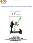
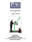
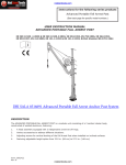
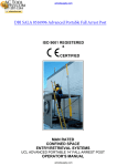
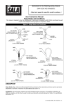
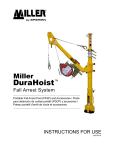
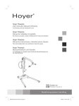
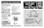
MAN RATED
CONFINED SPACE
ENTRY/RETRIEVAL SYSTEMS
PORTABLE FALL-ARREST SYSTEM
OPERATOR’S MANUAL
SERIAL NUMBER LOCATION
Always give your dealer or distributor the serial number of your MILLER DURAHOIST Portable
Fall-Arrest System when ordering parts or requesting service or other information.
The serial number plate is located where indicated. Please mark the number in the space
provided for easy reference.
SERIAL NUMBER LABEL
Model____________________________
Serial Number_____________________
Congratulations on your purchase of a MILLER DURAHOIST Portable Fall Arrest System. This
equipment has been designed and manufactured to meet the needs of a discriminating operator in the
variety of fall-arrest, confined space entry/retrieval and rescue situations.
Safe, efficient and trouble free operation and maintenance of your equipment requires that you or
anyone else who will be operating, maintaining or inspecting the equipment, read, understand and
follow all the Safety, Operation, Maintenance and Inspection instructions contained in this manual, and
in any related manuals referenced in this manual and/or supplied with the system.
This manual covers the MILLER DURAHOIST PORTABLE FALL-ARREST SYSTEM and Accessories
manufactured for MILLER. Use the Table of Contents or Index as a guide when searching for specific
information.
Keep this manual handy for frequent reference and to pass to new operators. Establish a regular
training program for experienced and new operators per these instructions. Establish a regular
maintenance and inspection program to keep the equipment in top condition.
The MILLER DURAHOIST PORTABLE FALL-ARREST SYSTEM is a modular system of Portable Fall
Arrest Anchor Posts, Extensions, and Support Bases designed to address a wide variety of Fall-Arrest
and Confined Space Entry/Retrieval and Rescue applications.
Modular components are labelled with the capacities and rating to which they were designed, tested,
and manufactured. The rating of any system is considered to be the rating of the lowest rated
component contained is the system.
Do not use the equipment if rating labels are damaged or illegible. New labels are available from Miller
or your local authorized dealer. When ordering replacement labels, be sure to include:
1) The part number from the bottom right hand corner of the label, when available.
2) The serial number of the unit.
3) The part (item) number of the component (consult the appropriate section of this
manual).
4) Any other numbers stamped on the components.
1
SAFETY ALERT SYMBOL
This Safety Alert symbol means
ATTENTION! BECOME ALERT!
YOUR SAFETY IS INVOLVED!
The Safety Alert symbol identifies important
safety messages on your MILLER Equipment
and in the manual. When you see this symbol,
be alert to the possibility of personal injury of
death. Follow the instructions in the safety
message.
Why is SAFETY important to you?
3 Big Reasons
SIGNAL WORDS:
Note the use of the signal words DANGER,
WARNING, and CAUTION with the safety
messages. The appropriate signal word for
each message has been selected using he
following guide-lines:
Accidents Disable and Kill
Accidents Cost You Money
Accidents Can Be Avoided
DANGER - Indicates an imminently hazardous
situation that, if not avoided, will
result in death or serious injury.
This signal word is to be limited to
the most extreme situations, or for
hidden or unseen hazards.
WARNING - Indicates a potentially hazardous
situation that if not avoided, could
result in death or serious injury,
and includes obvious and hidden
hazards. It may also be used to
alert against unsafe practices.
CAUTION - Indicates a potentially hazardous
situation that, if not avoided, may
result in minor or moderate injury.
It may also be used to alert
against unsafe practices.
2
SAFETY
YOU are responsible of the SAFE operation,
maintenance and inspection of your MILLER
DURAHOIST Portable Fall-Arrest System.
YOU must ensure that you and anyone else,
who is going to operate, maintain, inspect or
work around the equipment
be familiar with the operating and maintenance
procedures and related SAFETY information
contained in this manual. This manual will take
you step-by-step through your working day and
alerts you to all good safety and operating
practices while using the equipment.
Remember, YOU are the key to safety. Good
safety practices not only protect you, but also
the people around you. Make these practices a
working part of your safety program. Be certain
that EVERYONE operating this equipment is
familiar with the procedures recommended and
follows safety precautions. Remember, most
accidents can be prevented. Do not risk injury
or death by ignoring good safety practices.
•
•
•
•
•
Owners must give operating instructions to
operators or employees before allowing
them to use the equipment, and at least
annually thereafter.
The most important safety device on this
equipment is a SAFE operator. It is the
operator’s responsibility to read and
understand ALL Safety and Operating
instructions in the manual and to follow
these. All accidents can be avoided.
A person who has not read, been trained in
using and understood all operating and
safety instructions is not qualified to operate
this equipment. An untrained operator
exposes himself and others to possible
serious injury or death.
Do not modify the equipment in any way.
Unauthorized modification may impair the
function and/or safety and could affect the
life of the equipment.
Think SAFETY! Work SAFELY!
2.1
GENERAL SAFETY
1. Read, understand and follow the User
Manual and all safety signs before using,
maintaining or inspecting the equipment.
2. Refer to and follow applicable ANSI, OSHA,
CE or other Standards and local
regulations. Comply with requirements of
local regulations for your applications.
3. Establish an equipment–use training
program for experienced employees. Only
trained, competent persons shall use the
equipment. An untrained operator is not
qualified to operate the system.
4. Have a first-aid kit available for use should
the need arise and know how to use it.
5. Provide a fire extinguisher for use in case of
an accident. Store in a highly visible place.
6. Install and properly secure all guards and
shields before operating.
7. Wear appropriate protective gear. This list
includes but is not limited to:
-
-
A hard hat
Safety glasses
Protective shoes
with slip resistant
soles
Heavy gloves
Protective clothing
Face protection
8. Review and follow the Pre-Operation
Inspection before using a component in the
system or the system itself.
9. Establish a regular Maintenance and
Inspection program with your equipment
and maintain detailed records.
10. Review safety related items and operating
instructions with all personal on a regular
basis.
11. Be aware of your environmental
surroundings, be sure not to use the
equipment during an electrical storm. (this
equipment is conductive)
12. When using our winch with our equipment,
the noise level does not exceed 70 dB(A).
3
2.2
OPERATING SAFETY
1. Read, understand and follow the User
Manual and signs on the equipment before
using, maintaining or inspecting the
equipment.
2. Train all operators before allowing them to
use the equipment. An untrained operator
exposes themselves, bystanders and
co-workers to possible serious injury or
death.
3. Visually inspect the equipment and all
auxiliary components and equipment before
using. Correct any problems before using
the equipment.
4. Securely anchor all winches and /or SRL’s
before using, where applicable.
5. Use only certified anchor and connector
components in your system.
6. Use only an approved full body harness for
the workers.
7. Always work in teams. One person works in
the confined space and the other one pays
out the line and reels it in.
8. Do not use the winch when the brake wear
indicator displays excessive wear, the
overload indicator on the snap has been
activated, or Miller’s service interval has
been exceeded. Return winch to
manufacturer for service. (Refer to the
appropriate Winch Operators Manual for
detailed information on winch operation.)
9. Do not exceed the winch’s rated working
load during operation.
10. Establish a regular training program for new
and experienced workers.
11. Establish a detailed inspection program for
your equipment and document the findings.
Return the equipment to Miller for rework if
any problems are found.
4
12. Plan your work program before starting.
Have the required people, equipment and
procedures available to do the job.
13. Do not use the equipment around physical
or environmental hazards. This list
includes but is not limited to:
a. Corrosion that may affect the structural
integrity of the life line or other
components .
b. Chemicals which can degrade
components and not be visible.
c. Toxic gases: Rescuers or workers can
be killed in toxic environments.
d. Heat or elevated temperatures.
e. Moving machinery: Workers or
auxiliary equipment can be contacted
by or pulled into moving components.
f. Sharp edges: Workers or the
equipment can be injured or damaged
by sharp edges or components.
g. Electrical hazards: Stay away from
power lines or components carrying
electrical power.
h. Overload: Do not exceed rated
working load limit during operation.
i. Follow confined space regulations in
Standards.
2.3
MAINTAINANCE/INSPECTION
SAFETY
1. Read, understand and follow the User
Manual and signs on the equipment before
using, maintaining or inspecting the
equipment.
2. ANSI, OSHA & CE require a regular
inspection program for all Confined Space
Entry/Retrieval Equipment and to maintain
documented results of these inspections.
Follow the inspection procedure contained
in this manual and use the inspection form
to document the results.
3. Keep instructional and safety signs clean
and legible at all times. Clean or replace as
required.
4. Lubricate winch as per instructions in the
appropriate Winch Operators Manual.
5. Remove the equipment from service if a
problem is found during the inspection.
Return to an authorized repair depot or the
factory for service.
3
OPERATING, NEW
OPERATOR OR OWNERS
The MILLER DURAHOIST PORTABLE FALLARREST SYSTEM is designed to attach to a
person working at a height to provide protection
against injuries resulting from a fall. Various
accessories address a variety of fall-arrest
requirements, as well as confined space
entry/retrieval and rescue needs. Every new
operator must read, understand and follow the
instructions in all applicable manuals. No one
should be allowed to use the equipment without
training. The training should be reviewed with
experienced operators on a regular basis. At
regular intervals perform a detailed inspection
of the equipment and document the results.
Remove from service if deficiencies are found.
Alterations or misuse of this equipment or
failure to follow instructions, may result in
serious injury of death.
It is the responsibility of the owner’s
organization or operator to read this manual
and to train all other operators before they
start working with the equipment. Follow all
safety instructions exactly. Safety is
everyone’s business. By following
recommended procedures, a safe working
environment is provided for the operator,
bystanders and the area around the work
site. Untrained operators are not qualified
to operate the equipment.
Many features incorporated into this equipment
are the result of suggestions made by
customers like you. Read this manual carefully
to learn how to operate the equipment safely
and how to set it to perform as intended. By
following the operating instructions in
conjunction with a good maintenance program,
your equipment will provide many years of
trouble-free service.
5
OPERATING SAFETY
1. Read, understand and follow the User
Manual and signs on the equipment before
using, maintaining or inspecting the
equipment.
2. Train all operators before allowing them to
use the equipment. An untrained operator
exposes themselves, bystanders and
workers to possible serious injury or death.
3. Visually inspect the equipment and all
auxiliary components and equipment before
using. Correct any problems before using
the equipment.
4. Securely anchor the winch before using.
5. Use only certified anchor and connector
components in your system.
6. All anchor points, or mounting/setup
locations for permanent or portable systems
must be approved to local standards by a
qualified engineer.
7. Use only an approved body harness for the
workers.
8. Always work in teams. One person works in
the confined space and the other one pays
out the line and reels it in.
9. Do not use the winch when the brake wear
indicator displays excessive wear, the
overload indicator on the snap has been
activated, or Miller’s service interval has
been exceeded. Return winch to
manufacturer for service. (Refer to the
appropriate Winch Operators Manual for
detailed information on winch operation.)
10. Use only retractable lifelines or shock
absorbers with a maximum arrest force
(MAF) rating equal to or lower than ½ of the
strength of the lowest rated component of
your system.
6
11. Establish a regular training program for
new and experienced workers.
12. Establish a detailed inspection program for
your equipment and document the findings.
Return the equipment to Miller
for rework if any problems are found.
13. Plan your work program before starting.
Have the required people, equipment and
procedures available to do the job.
14. Do not use the equipment around physical
or environmental hazards. This list
includes but is not limited to:
a. Corrosion that may affect the structural
integrity of the life line or other
components.
b. Chemicals which can degrade
components and not be visible.
c. Toxic gases: Rescuers or workers can
be killed in toxic environments.
d. Heat or elevated temperatures.
e. Moving machinery: Workers or
auxiliary equipment can be contacted
by or pulled into moving components.
f. Sharp edges: Workers or the rescue
equipment can be injured by or
damaged by sharp edges or
components.
g. Electrical hazards: Stay away from
power lines or components carrying
electrical power.
h. Overload: Do not exceed rated
working load limit during operation.
i. Follow confined space regulations in
Standards.
j. Noise: wear appropriate noise
protection where necessary.
k. Environmental hazards: do not operate
equipment during electrical storms.
3.1
PORTABLE FALL ARREST
POST
3.1.1
General
The MILLER DURAHOIST PORTABLE
FALL-ARREST POST is a modular unit
consisting of a 3 section tubular body,
constructed of welded aluminum, featuring:
1. A head assembly equipped with 3
independent swivel tie-off rings.
2. Various accessories to address different
situations.
3. Adjusting screws for vertical leveling of the
Fall-Arrest Post when installed on inclined
surfaces.
4. Featuring adjustable height option from 33.0
(840mm) to 57.5 (1460mm) inches.
Figure 3.1.1
WARNING
WARNIN G
The Davit Arm Assembly and Anchor Post
Extension have some application restrictions
when used in different types of applications.
Use of Portable Fall-Arrest System
Accessories may affect the rating of the
Portable Fall-Arrest System Anchor Post in
various situations. The rating of any system
is the rating of the lowest rated component in
that system.
7
When using a MILLER DURAHOIST
PORTABLE FALL-ARREST SYSTEM the
rating of any
particular system is defined as the rating of the
lowest rated component in the system. Check
the rating label on each system component
before using to ensure that the rating meets all
applicable regulatory requirements.
Do not use any equipment on which any of the
warning, rating or other labels have been
removed, become damaged, or are otherwise
illegible. Refer to Section 5 of this manual
“Labels”, or to the appropriate section of the
applicable system manual for information on
ordering replacement labels.
3.1.2
Regulations governing Fall Protection,
Confined-Space Entry/ Retrieval and Rescue
Procedures vary with jurisdiction. It is the
responsibility of the owner and/or user of this
equipment to be aware of applicable regulations
and ensure that equipment selected for each
job complies with these requirements.
Refer to the appropriate section of this or
any other applicable manuals for specific
information on the installation and use of
the type of base you are using prior to
using the system.
Setting Up the Portable Fall Arrest
Post
The MILLER DURAHOIST PORTABLE FALLARREST SYSTEM POST is designed for use
with a variety of portable and permanent mount
support bases. Consult the appropriate section
of this manual or separate manuals when
setting up or installing any MILLER Portable
Fall Arrest Bases.
Step 1: Before setting up for any work at
heights, fall arrest, or confined space entry
be sure that you have all equipment
required to safely carry out the work to be
performed, and to meet all applicable
standards and regulations for your area.
Step 2: Set-up or locate the Portable Fall
Arrest System Base intended for use in
the application according to the
instructions in the applicable section of this
manual. Ensure that the base is
structurally sound and free of any
corrosion or contamination which may
affect the insertion of the connecting pin or
the structural integrity of the base.
8
Step 3: As shown in Fig. 3.1.3, insert the
Portable Fall Arrest Post (13) between the
base plates tabs (1) and visually align the
¾” holes as shown in Fig. 3.1.3.B. Secure
the Post by inserting the ¾” pin (2)
through the base plate tabs (1) and sleeve
(13). Make sure the pin fully engages
both the base plate tabs (1) and the entire
Post to lock the Post firmly in place.
Step 4: Extend the post (13) by loosening triscrew (4a) and removing section 1 pin (5)
from section 1, Figure 3.1.2 A, lift section
2 and align the pin holes, secure section 2
in section 1 by fully engaging section 1 pin
(5). The post should look like Figure 3.1.2
B.
Loosen tri-screw (4b) and lift section 3
and align pin holes with section 2, Figure
3.1.2 B and secure the Post section 3 by
using section 2 pin (6). The post should
look like Figure 3.1.3 A.
Hand tighten both tri-screws (4).
Step 5: The Portable Fall-Arrest Post (Fig.
3.1.3A) must be in a vertical position at all
times when it is being used as a Fall13
Arrest anchor point. Depending on the
type of base you are using the Post may
be leveled by using the adjuster screws
(3) the base plate (10) or a combination of
these. The adjuster screws are
alternately loosened and tightened to level
the Post.
13
Figure 3.1.2 A
Figure 3.1.2 B
9
8
12
Step 6: Install any accessories (eg. Anchor
Post Extension) that installs in the sleeve
(9) at the top of the Portable Fall Arrest
Post. Refer to the applicable section of
this or other applicable accessory
manuals for any accessories being used
with this system.
14
8
8
Step 7: Depending on the nature of the entry
and the standards and regulations
governing Confined Space Entry/
Retrieval and Rescue requirements in
your area, a Personal Fall-Arrest System
(PFAS) connected to the entrant may be
required. It is the responsibility of the
operator to be aware of these
requirements and follow them. Always
wear a full body harness when attached to
a PFAS to minimize potential injury.
Step 8: Once the system is set-up inspect all
components, fasteners, and other parts
for wear, damage, corrosion, looseness,
or any other condition that may reduce the
integrity of the system. Components
which are worn, damaged, corroded, or
loose, must be tagged, marked with “DO
NOT USE” or like wording and prevented
from being used until repaired or replaced
as required.
Step 9: Following all instructions contained in
Miller’s instructions for any PFAS or any
other devices being used, the appropriate
section of this manual or other manuals
for any MILLER Accessories being used,
and all applicable standards or regulations
governing Fall Protection, Confined Space
Entry/ Retrieval and Rescue for your area
proceed with the work.
1
2
3
4
5
6
7
8
9
10
11
12
13
14
13
Figure 3.1.3 A
Figure 3.1.3 B
10
Base Tab Plates
¾” Pin
Adjuster Screw
Tri-Screw
Section 1 Pin
Section 2 Pin
Section 3 Pin
Swivel Tie Off
Rings
Extension Sleeve
DH-Anchor Plate
Carrying Handle
Davit Anchor
Ring
PFA Post
HLL Anchor Ring
3.1.3 Using the Portable Fall Arrest Mast for
Horizontal Lifeline (HLL) Applications
3.1.3.1 General
The MILLER DURAHOIST Portable Fall Arrest
Mast can be used for most temporary
Horizontal Lifelines (HLL) applications,
therefore using existing mounting bases as the
temporary base for HLL applications.
3.1.3.2 Setting up the Portable Fall Arrest
Post for HLL use
When using this post for HLL applications, it is
critical to know when to use a tie-back and
when not to use a tie-back to support the HLL
loads. Refer to the chart Figure 3.1.6 to confirm
what loads can be sustained by the MILLER
Portable Fall Arrest Post unsupported by a tieback.
Follow all labels carefully when setting up for
HLL applications and refer to the chart when
unsure of load ratings.
Step 1: Follow set-up instructions in section
3.1.2 of this manual.
Step 2: The post can be used without the
installation of a tie-back as shown in
Figure 3.1.4a. Refer to the “HLL Chart
Positions & Ratings”, Figure 3.1.6 for
maximum ratings without the use of a
tie-back.
Step 3: Using the mast with the second and/or
third stage erected (Positions 4, 3 & 2)
and HLL load ratings that exceed the
load rating shown in the chart, Figure
3.1.6, must have tie-backs installed as
shown in Figure 3.1.4b.
Step 4: Using the davit arm with a HLL requires
the third section, (Positions 4 & 3) of the
mast to be erected to install the davit
arm sleeve. Refer to the chart to verify
tie-back use.
Refer to section 3.3.3.1 of this manual for Davit
Arm set-up.
Step 5: Install HLL using the carabineer
supplied with the HLL assembly to the
HLL Anchor Ring provided on the mast
as shown in Figure 3.1.5. Follow all
manufactures instruction carefully when
installing a HLL.
If you require a tie-back, install the tieback using the opposite eye across from
the installed HLL on the HLL Anchor
Ring.
Tie-back anchors must be designed and
approved by the MILLER and the structure
mounting requirements approved by a
qualified engineer. Call MILLER to purchase
the suitable tie-back for the application.
The MILLER Portable Fall Arrest Post with
HLL Anchor Ring can also be used as an
intermediate for a HLL to spanning across
longer distances.
11
Figure 3.1.6, HLL Load Ratings Chart
Positions
1
2
3
4
12
No Tie-back Required
Maximum Load Rating
3250 lbs
4250 lbs
4000 lbs
5700 lbs
HLL Anchor
Ring Height
57.25 inches
44 inches
46 inches
32.75 inches
3.2
MOUNTING BASES
3.2.1
DH-Anchor Plates
DH-Anchor Plates are designed to be
permanently welded to existing structures in
locations of frequent work, or where use of
portable base is impractical. These
mounting plates are compatible with all
MILLER DURAHOIST PORTABLE FALLARREST SYSTEM Posts and
Accessories. DH-Anchor Plates
permanently address Portable Fall-Arrest
Anchor Post mounting base requirements
for steel structures.
3.2.2
Installing DH-Anchor Plates
Specific installation instructions are beyond
the scope of this product operator’s manual.
Consult MILLER DURAHOIST Product
Specification Sheets for detailed information
on welding procedures, mounting
requirements and application restrictions.
3.2.3 Set-up of the Portable Fall-Arrest Post
Install and level the Portable Fall-Arrest
Post as outlined in Section 3.1.2.
WARNING
WARNING
All anchor points or mounting/set-up
locations for permanent or portable
systems must be approved to local
standards by a qualified engineer and must
comply with all mounting requirements and
application restrictions as outlined on the
applicable MILLER Product Specification
Sheet. Failure to follow this restriction may
result in serious injury or death.
13
3.3
3.3.1
PORTABLE FALL-ARREST
POST ACCESSORIES
General
The MILLER DURAHOIST PORTABLE FALLARREST POST may be equipped with a variety
of accessories to meet additional confined
space entry/retrieval, rescue, or fall protection
requirements. Use of these accessories may
affect the rating and load carrying capacities of
the Portable Fall-Arrest Post. Be aware of any
limitations imposed on the system by the use of
various accessories, and follow any restrictions
given on the various product specification
sheets, warning labels, this manual and/or
related manuals.
All MILLER DURAHOIST PORTABLE FALLARREST SYSTEM and Accessories are
designed for use with shock absorbers and
retractable devices having a Maximum Arrest
Force (MAF) rating of 900 lb. (4 kN) or less.
Shock absorbers and retractable devices must
be installed, maintained and used according to
Miller’s instructions.
14
WARNING
The 14-inch Anchor Post Extension and Davit
Arm Assembly have some application
restrictions when used in different types of
applications. The use of these accessories derates the system to two workers tied of to the
swivel tie-off head (8), Fig.3.1.3. Failure to
follow this restriction may result in serious injury
or death.
3.3.2 14” Anchor Post Extension
The 14 inch Post Extension (Pt.# DH-AP-2) is
designed to provide a single fall-arrest tie-off
point 14 inches above the post’s swivel tie-off
rings (See Figure 3.3.1). Use of the 14 inch
Post Extension de-rates the Portable Fall-Arrest
Post to only two anchor points on the swivel tieoff rings.
For use of the Anchor Post Extension & Davit
Arm Assembly together refer to Section 3.3.3 of
this manual.
3.3.2.1 Set-Up of the 14” Anchor Post
Extension
Install the Portable Fall-Arrest Post following
the installation procedure in Section 3.1.2.
Step 1: Shown in Fig. 3.3.1, insert the 14-inch
Post Extension (14) into the post (9). Pin the
post into position by aligning the holes and
inserting the ½ inch pin (7) completely through
the Post.
Step 2: Attach the Fall-Arrest Device to the
anchor point eye (15).
3.3.2.2 Using the 14” Anchor Post
Extension
Connect a shock absorber/ retractable device
using a sufficiently rated carabineer to anchor
point eye (15).
Using the 14” inch anchor post extension (14)
limits the use of only 2 attendants anchored to
the Portable Fall Arrest post swivel rings (8) for
fall protection.
Figure 3.3.1
15
3.3.3
Anchor Post Davit Arm Assembly
The Anchor Post Davit Arm (Pt.# DH-AP-3) is
designed to provide a means of access/egress,
rescue, and material handling applications (See
Figure 3.6.1). Use of the Anchor Post Davit
Arm de-rates the Portable Fall-Arrest Post to
only two anchor points on the swivel tie-off
rings.
Using the 14” Anchor Post Extension combined
with the Anchor Post Davit Arm de-rates the
Portable Fall Arrest Post to only one anchor
point on the swivel tie-off rings.
3.3.3.1 Set-Up of the Anchor Post
Davit Arm Assembly
Install the Anchor Post/ Davit Arm
Assembly starting with and following
the installation procedure in Section
3.1.2.
Step 1: Shown in Figure 3.3.2.1,
clamp the Davit Arm Sleeve (8) over
Section 3 (7) of the Portable Fall
Arrest Post.
Step 2: Install and secure the Davit
Arm Sleeve (8) by closing the sleeve
around section 3 (7), Figure
3.3.2.1and hand tightening the clamp
knob screws (12) shown in Figure
3.3.2.2.
1
2
3
4
5
6
7
8
9
10
11
12
13
14
3/8” Pin
Assembly
Davit Anchor Eye
Cable Assembly
U-Bracket
Carabineer
Section 2
Section 3
Davit Arm Sleeve
Davit Arm
Receiver Tube
Head Pin
Assembly
Clamp Screw
Knobs
PFA Post
Davit Head
Assembly
Mounting
Brackets
Figure 3.3.2
11
8
16
Figure 3.3.2.1
Figure 3.3.2.2
Step 3: Insert the Davit Head Assembly (15)
and align one of the three 3/8” pin holes in the
Davit Arm Receiver Tube. Using the pin (1)
secure the Davit Arm into position and to vary
the offset.
The Portable Fall Arrest Post may be used as a
fall arrest anchor point during a rescue
scenario. Alternative anchor points for fall
protection use should be identified and planned
for use during a rescue scenario.
Step 4: Shown in Figure 3.3.2.4, secure the
cable assembly (3) to the Portable Fall Arrest
Post (13) using the carabineer (5) provided and
connecting it to the Davit Arm Anchor Eye (2),
Figure 3.3.2.5.
9
1
3
5
9
2
Figure 3.3.2.4
Figure 3.3.2.3
3.3.3.2 Using the Davit Arm Assembly
The Davit Arm Assembly is designed with offset
adjustability and 360 degree rotation. This
Davit Arm Assembly allows the combined use
of an entry/ retrieval winch and a self-retracting
lifeline (SRL). See Section 3.3.4 for details on
mounting the winch and SRL.
Step 1: Adjust the offset by pulling the pin
assembly (1) and selecting the one of three
holes offered in the Davit Arm receiver tube (9)
as shown in Figure 3.3.2.3.
3.3.3.3 Rescue
The Davit arm can be rotated 360 degrees in a
rescue/ retrieval situation so an injured worker
can be moved to a safe environment. The
Portable Fall Arrest Post must be used in a
vertical position at all times to effectively rotate
the Davit Arm.
17
3.3.4
Mounting Brackets for Winch and
SRL
WARNING
WARNING
The mounting brackets are for use with the
Davit Arm Assembly. Winches and SRL’s must
have a 310 lbs working load and SRL used with
the system must have an MAF rating of 900 lbs
or less.
3.3.4.1 Set-up of the Mounting Brackets
The Adaptor Brackets for your winch or SRL
must be offset to the side that the crank handle
is on to eliminate interference between the
crank handle and the Davit Arm Assembly and
the mounting brackets. Not following these
instructions can impair retrieval capabilities that
can cause serious injury or death.
The mounting brackets will be bolted onto the
Davit Arm Assembly when shipped from Miller.
The brackets are arranged to most common
Winch/ SRL configuration. If these brackets
need to be repositioned to suit your application,
remove the two bolts securing the bracket to
the Davit Arm Receiver Tube (9) shown in
Figure 3.3.3, reposition to other bracket mount
location and replace bolts and tighten.
Bracket bolts
9
Figure 3.3.3
Bracket mount
locations
3.3.4.2 Using the Mounting Brackets
Install and use the winch and/or SRL according
to manufacturer’s instructions.
Proper operation and maintenance of the winch
and/or SRL are critical to the safe usage of your
MILLER DURAHOIST PORTABLE FALL
ARREST SYSTEM.
18
9
3.3.5 Winch and SRL Operation
Shown with the accessories in Section 3.3, is
the DURAHOIST DH50/50A Man-Rated Winch
available for use with the MILLER DURAHOIST
PORTABLE FALL-ARREST SYSTEM. The
winch is necessary for worker positioning and
rescue situations when using the Davit Arm
Assembly. The winch is available in a variety of
lifeline capacities, and lifelines are available in a
variety of lengths and materials.
Proper operation and maintenance of the winch
are outlined in the “DH50/50A Winch Operator’s
Manual”, MILLER Pt. # 18713 supplied with
every winch.
Winches and SRL’s must used and maintained
in accordance with Miller’s instructions, please
refer to the instruction manual provided with
your winch or SRL.
3.7 STORAGE
Prior to storage, the Portable Fall Arrest
System should be thoroughly inspected
and maintained. Return for repair or
replacement of any worn or damaged
components to prevent any
unnecessary down time at the next use.
Follow this procedure:
1. Thoroughly clean the Portable Fall
Arrest system using mild soap on
the body and labels. Be sure the
labels are legible. Refer to Section 5
for information on ordering
replacement labels if any are
damaged or become illegible.
2. Use a neutralizing solution to clean
lifeline. This is particularly important
if the unit had been used in corrosive
or toxic environments.
3. Perform a complete inspection of the
unit and document the results.
4. Touch up all nicks and scratches to
prevent corrosion.
5. Store in a cool dry place.
19
4 MAINTENANCE AND INSPECTION
MAINTENANCE/INSPECTION SAFETY
1. Read, understand and follow the
User Manual and signs on the
equipment before using, maintaining
or inspecting the equipment.
2. ANSI and OSHA requires a regular
inspection program for all Confined
Space Entry/Retrieval Equipment
and to maintain documented results
of these inspections. Follow the
inspection procedure contained in
this of any other applicable the
manual and use the inspection
form(s) to document the results.
4.1
Maintenance
4.1.1
Maintenance Intervals
3. Keep instructional and safety labels clean
and legible at all times. Clean or replace as
required. See Section 5 for label
information and part numbers.
4. Lubricate winch as per instructions in Winch
Operator’s Manual.
5. Remove the equipment from service if a
problem is found during the inspection.
Return to an authorized repair depot or the
factory for service.
Daily
Annually or As Required
1. Visual Inspection
Perform a complete visual inspection. Refer
to Section 4.2.1. Remove from service if a
defect is found. Refer to Winch Operator’s
Manual for visual inspection procedure for
the DURAHOIST DH50/50A winch.
1. Clean Portable Fall Arrest System
Thoroughly clean the Portable Fall Arrest
system using mild soap on the body and
labels. Be sure the labels are legible. Refer
to Section 5 for information on ordering
replacement labels if any are damaged or
become illegible.
Weekly
1. Functional Inspection
Perform a functional inspection. Refer to
Section 4.2.2. Record results and keep
documentation.
20
2. Complete Inspection
Perform a complete inspection. Refer to
Section 4.2 & 4.3. Record results and keep
documentation.
4.2
Inspection
4.2.1
Visual Inspection
A complete visual inspection should be
performed on the Portable Fall-Arrest System
equipment you are using prior to the operation.
The following items should be checked; and the
results recorded on the “Inspection Log” sheet
(see Section 4.3).
1. Labels
Check that all labels are clean and legible.
Clean the labels if any are dirty using a mild
soap and a damp cloth. Replace if any are
illegible (Refer to Section 5 for a listing of all
labels).
2. Fasteners
Check that all screws and other fasteners
are tight. If any are loose, tighten as
required. Contact your MILLER dealer or
Miller for any replacement
fasteners that may be required.
3. Structural Components
Check the components for cracks, dents,
bends, or breaks. Minor cosmetic damage
in the component body will not affect the
function of the Portable Fall-Arrest System.
However if there are major dents or any
other structural damage, the unit should be
removed form service and returned to Miller
for service.
4. Corrosion
Check all components for damage from
corrosion. Although all components resist
corrosion, working in corrosive
environments can lead to damage. Inspect
all structural components and fasteners for
signs of damage. If corrosion damage is
found, remove from service and return to
Miller for service.
5. Basic Winch Inspection
Check the winch following the procedure in
the DURAHOIST DH50/50A Winch
Operator’s Manual,
Part # 18713 and carefully document all
findings as listed.
21
4.2.2 Functional Inspection
A functional check should be performed on the
Portable Fall-Arrest System prior to every use.
The following functional tests should be done;
and the results recorded on the “Inspection
Log” sheet (Section 4.3).
1. System Operation and Adjustments
The Portable Fall Arrest System contains
operational parts that may include pulleys
and /or rollers. These parts must be
carefully checked for chips, cracks, or worn
areas that can cause malfunction during
operation of the system.
Make sure that all the adjustment points are
in full functional condition. This may include
parts that contain pins, bolts, tri-screws, and
adjusting screws. There are also
mechanical adjustments which may include,
adjustable legs, sleeves, adjustable sliding
blocks, and brackets. These areas must be
kept clean from debris and corrosion for
proper functional use. If any part of the
system that includes all listed items above
becomes damaged contact your local dealer
or manufacturer for parts and/or service.
2. Basic Winch Inspection
Refer to the Basic Winch Operator’s
Manual, Pt.# 16182 (where applicable) for
proper functional inspection procedures for
the Basic winch and lifeline.
3. SRL and other Accessory Inspection
Refer to the manufacture’s operator’s
manual or instructional material for proper
functional inspection procedures for SRL’s
and accessories not covered by this
manual.
22
21
5
LABELS
5.1 Warning Labels
The MILLER DURAHOIST PORTABLE FALLARREST SYSTEM uses a label rating system
that is attached to all components on the
system.
The operator and/or entrant must establish
the local standards by a qualified engineer and
only then, a decision can be made by the rating
labels as to which is the lowest rated
component and if it meets or exceeds local
standards.
Proper maintenance of the labels must be
established by the operator/entrant to keep
system use safe. If labels are damaged the
operator/entrant must enforce a lock-out/tag-out
procedure. New labels are available from
Miller.
22
5 Labels con’t
Operator Instructions:
To equipment user- you must read and understand the operator’s manual or have the
instructions explained to you before each using this product.
Visually inspect the hoist and its components for damage and/or missing hardware. If
defects are found remove from service using lock out/tag-out procedures.
Visually inspect all warning labels to make sure they legible, if not remove from service
and order replacement labels from the manufacturer.
Any alteration or misuse of this equipment can result in serious injury or death.
Davit Arm Instructions:
Clamp the davit arm shell around the third section of the Portable Fall Arrest Post;
tighten down both screws to secure.
Connect carabineer to the Davit Anchor marked “DVT”.
Pull the pin and adjust the offset according to applications height and reach.
Maximum 3 persons tied off to the UCL Portable Fall Arrest system at any given time
with any UCL approved accessories.
Horizontal lifeline (HLL) Instructions:
For HLL applications, refer to Section 3.1.3 of the operator’s manual Pt# 17022 or
17451 for combined use with the davit arm.
Specifications:
Personnel Load Capacity: 310 lbs. @ 10:1 Safety Factor
Material Load Capacity: 620 lbs. @ 5:1 Safety Factor
Materials and Construction:
General construction: Powder Coated, Welded Aluminum
Weld Certification: CWB 47.2
Tubular Components: 6061-T6 Alum.
Other Components: HD Plastic, HR Steel
Steel Components: CS500 Plated
Block Anchor: Stainless Steel
Hardware: Gr.5/Gr.8 Steel, Zinc Plated
Compliance:
ANSI Z117.1-1989, OSHA 1910, ANSI Z359.1-1992 (Anchor Point Only) EN
795, EN 364, ISO 14567
Pt# 17434
23
6 SPECIFICATION SHEETS
6.1 General
These specification sheets contain information
necessary for the proper installation and use of
the equipment mentioned in this manual. These
specifications contain application specific ratings
and mounting requirements determined through
design and testing.
Please read and follow these specification sheets
carefully to ensure the proper installation of each
item.
24
7 REPLACEMENT PARTS
7.1 General
These drawings are to provide you with an easy
reference to order replacement labels and parts
when required. Please follow each of the
drawings to locate the part numbers required to
order from MILLER by either referencing the bill
of materials on the right hand side of the drawing
and then locating the balloon pointing out the
replacement part for verification or visa versa.
25
31
DH-AP-2
DH-AP-1
DH-AP-1
DH-AP-3
DH-AP-3
1345 15th Street
Franklin, PA, USA
16323
PHONE (814) 432-2118
FAX (814) 437-2973
www.bacou-dalloz.com
PRINTED IN USA
ISSUE DATE: November 24, 2004
REVISION NUMBER 01
PART NUMBER: 18716