1
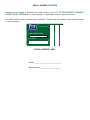
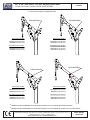
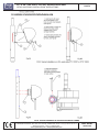
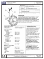
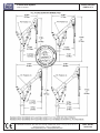
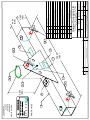
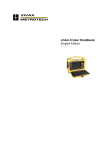
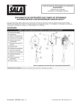
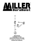
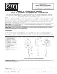
LIMITED WARRANTY This Limited Warranty is given exclusively to: Name Address Telephone No. by Unique Concepts Ltd. (“Unique Concepts”) in respect of the following product(s) manufactured by it (the “Products”): Subject to the conditions and restrictions contained in this Limited Warranty, Unique Concepts warrants to the Customer that the Products are free from defects in materials and workmanship under normal use and service for a period of twelve (12) months from the date the Products are purchased by the Customer, in new and unused condition, from Unique Concepts or its agent (the “Warranty Period”). Unique Concepts’ entire liability and the Customer’s exclusive remedy regarding any such defects is limited to the repair or replacement of the defective Products (as Unique Concepts, in its sole discretion, deems appropriate) which are returned to Unique Concepts in accordance with the procedures set forth below. Terms and Conditions 1. This Limited Warranty will be void unless: (a) this Limited Warranty is fully completed by or on behalf of the Customer and returned to Unique Concepts within fourteen (14) days following the date the Customer purchases the Products, by registered mail addressed to: Unique Concepts Ltd., 1500 King Edward Street, Winnipeg, Manitoba, R3H 0R5 (the "Manufacturer’s Address”); (b) written notice of any defect is delivered to the Manufacturer’s Address by registered mail within five (5) days after any defect in the Products becomes apparent; and (c) any defective Products in respect of which the Customer wishes to make a warranty claim are delivered to Unique Concepts, with all postage or freight charges prepaid, within the Warranty Period and no later than fourteen (14) days after any defect in the Products becomes apparent. 2. This Limited Warranty shall not apply to any Products which have been used with unapproved assemblies or sub-assemblies, or which have been customized or modified, altered, damaged or misused. 3. Following the repair or replacement of any defective Products in respect of which a warranty claim is validly made by the Customer, or, alternatively, following the date Unique Concepts determines either that the warranty given hereby has been voided or that the returned Products do not exhibit any defects in materials or workmanship, Unique Concepts will return the Products to the Customer. All such shipments will be made to the Customer’s address listed above, and will be at the Customer’s sole expense. I 4. The Customer will incur all risk of loss, theft or damage to the Products during shipment to Unique Concepts and during their subsequent return to the Customer. Without limiting the foregoing, the common carrier chosen by Unique Concepts to return the Products to the Customer will be deemed to be an agent of the Customer. 5. If, on its inspection of any Products returned to it by the Customer, Unique Concepts determines that such Products require maintenance or repairs which are outside the scope of its warranty obligations. Unique Concepts may contact the Customer with a view to obtaining authorization (which may be written or oral) to complete such maintenance or repairs at rates then customarily charged by Unique Concepts to its customers. The Customer hereby releases and indemnifies Unique Concepts, together with its directors, officers, agents, employees, successors and assigns, and anyone else who has been involved in the inspection of the Products returned by the Customer, from all claims, losses, expenses and damages (including damages for loss of business profits, business interruption, loss of business information, loss of health or for any other loss whatsoever) arising directly or indirectly, as a result of the failure by Unique Concepts to perform or adequately perform any maintenance or repairs which are outside the scope of its warranty obligations hereunder, whether or not resulting from any negligent or improper inspection of such Products, or from the failure of the Customer to authorize the performance of such maintenance or repairs. 6. THE WARRANTY SET OUT HEREIN IS THE ONLY WARRANTY OF ANY KIND, EITHER EXPRESS OF IMPLIED, STATUTORY OR OTHERWISE (INCLUDING BUT NOT LIMITED TO THE IMPLIED WARRANTIES OR MERCHANTABILITY AND FITNESS FOR A PARTICULAR PURPOSE) THAT IS MADE BY UNIQUE CONCEPTS. WITHOUT LIMITING THE GENERALITY OF THE FOREGOING, UNIQUE CONCEPTS DOES NOT WARRANT THAT THE PRODUCTS WILL MEET ALL REQUIREMENTS OF ALL APPLICABLE LAWS, REGULATIONS OR OTHER ENACTMENTS APPLICABLE IN EACH JURISDICTION IN WHICH THEY MAY BE USED OR STORED, OR THE REQUIREMENTS OF THE CUSTOMER. 7. NO ORAL OR WRITTEN INFORMATION OR ADVICE GIVEN BY UNIQUE CONCEPTS, ITS DEALERS, DIRECTORS, OFFICERS, DISTRIBTORS, AGENTS OR EMPLOYEES SHALL CREATE A WARRANTY OR IN ANY WAY INCREASE THE SCOPE OF THIS LIMITED WARRANTY, AND THE CUSTOMER MAY NOT RELY ON ANY SUCH INFORMATION OR ADVICE. 8. THE CUSTOMER AGREES THAT, TO THE MAXIMUM EXTENT PERMITTED UNDER APPLICABLE LAW, NEITHER UNIQUE CONCEPTS NOR ITS DEALERS, DIRECTORS, OFFICERS, DISTRIBUTORS, AGENTS OR EMPLOYEES, OR ANYONE ELSE WHO HAS BEEN INVOLVED IN THE CREATION, PRODUCTION OR DELIVERY OF THE PRODUCTS, WILL BE LIABLE FOR ANY DIRECT, INDIRECT, CONSEQUENTIAL OR INCIDENTAL DAMAGES (INCLUDING DAMAGES FOR LOSS OF BUSINESS PROFITS, BUSINESS INTERRUPTION, LOSS OF BUSINESS INFORMATION, LOSS OF HEALTH OR ANY OTHER LOSS WHATSOEVER) ARISING OUT OF THE USE OR INABILITY TO USE SUCH PRODUCT, EVEN IF UNIQUE CONCEPTS HAS BEEN ADVISED OF THE POSSIBILITY OF SUCH DAMAGES. 9. The Customer is not entitled to assign this Limited Warranty to any party. To the maximum extent permitted under applicable law, and at its sole discretion, Unique Concepts is entitled to assign its obligations hereunder to any third party. 10. This Limited Warranty is governed by the laws of the Province of Manitoba and will benefit Unique Concepts and its successors and assigns. II ACKNOWLEDGEMENT THE CUSTOMER ACKNOWLEDGES THAT HE/SHE HAS READ THIS LIMITED WARRANTY, UNDERSTANDS IT, AND AGREES TO BE BOUND BY ITS TERMS AND CONDITIONS. THE CUSTOMER FURTHER AGREES THAT THIS LIMITED WARRANTY CONTAINS THE COMPLETE AND EXCLUSIVE STATEMENT OF AGREEMENT BETWEEN THE PARTIES, AND SUPERSEDES ALL PROPOSALS OR PRIOR AGREEMENTS ORAL AND WRITTEN, AND ANY OTHER COMMUNICATIONS BETWEEN THE PARTIES, RELATING TO THE SUBJECT MATTER OF THIS LIMITED WARRANTY. Date Customer WARRANTY VOID IF NOT REGISTERED III UNIQUE CONCEPTS CONFINED SPACE ENTRY/RETRIEVAL UCL ADVANCED 12-29” ADJUSTABLE VARIABLE OFFSET HOIST SYSTEM WARRANTY REGISTRATION FORM & INSPECTION REPORT WARRANTY REGISTRATION (please print) This form must be filled out by the dealer and signed by both the dealer and the customer at the time of delivery. Customer’s Name________________________ Dealer Name________________________ Address________________________________ Address____________________________ City, State/Province, Code__________________ City, State/Province, Code______________ Phone Number ( ____ )____________________ Phone Number ( ____ )________________ Contact Name____________________________ Manufactured by: Unique Concepts Ltd. 1500 King Edward Street, Unit 1 Winnipeg, Manitoba, Canada R3H 0R5 Phone Number (204) 694-7432 Fax Number (204) 694-7612 Toll Free 1-800-455-9673 Model __________________________________ Serial Number ___________________________ Delivery Date ____________________________ DEALER INSPECTION REPORT SAFETY ___ All Appropriate Fasteners Torqued ___ Check that all fasteners and mechanical components are present ___ Check Winch with Winch Warranty Card ____ No Mechanical Damage ___ Check for finish damage ____ All Labels Installed Correctly and Legible ____ Review Operating and Safety Instructions I have thoroughly instructed the buyer on the above described equipment which review included the Operator’s Manual content, equipment care, adjustments, safe operation and applicable warranty policy. Date ____________________ Dealer’s Rep. Signature _______________________ The above equipment and Operator’s Manual have been received by me and I have been thoroughly instructed as to care, adjustments, safe operation and applicable warranty policy. Date ___________________ Owner’s Signature ___________________________ Please cut out, photocopy for your records and send signed original back to UCL. IV SERIAL NUMBER LOCATION Always give your dealer or distributor the serial number of your 12"-29" ADJUSTABLE/ VARIABLE OFFSET HOIST SYSTEM when ordering parts or requesting service or other information. The serial number plate is located where indicated. Please mark the number in the space provided for easy reference. MADE IN CANADA Pt#: 12817 Rev.03 SERIAL No. MFG DATE: LOT No. COMPONENT MODEL: SYSTEM MODEL: www.capitalsafety.com SERIAL NUMBER LABEL Model____________________________ Serial Number_____________________ 1 INTRODUCTION Congratulations on your choice of a Unique Concepts Man Rated Confined Space Entry/Retrieval 12” (305 mm) to 29” (737mm) Adjustable/Variable Offset Hoist System to compliment your entry/retrieval operation. This equipment has been designed and manufactured to comply with the requirements of ANSI Z 359.1-1992, A 10.14-1991 & CE to meet the needs of a discriminating operator for the efficient entry/or retrieval of people from a confined space. Safe, efficient and trouble free operation and maintenance for your component or system requires that you or anyone else who will be operating, maintaining or inspecting the equipment, read, understand and follow all the Safety, Installation, Operation, Maintenance and Inspection instructions contained in this manual, and in any related manuals referenced in this manual and/or supplied with the system. This manual covers the 12” to 29”Adjustable/ Variable Offset Hoist System manufactured by Unique Concepts. Use the Table of Contents or Index as a guide when searching for specific information. Keep this manual handy for frequent reference and to pass to new operators. Establish a regular training program for experienced and new operators per these instructions. Establish a regular maintenance and inspection program to keep the equipment in top condition. Modular components are labeled with the capacities and rating to which they were designed, tested, and manufactured. The rating of any system is considered to be the rating of the lowest rated component contained is the system. Do not use the equipment if rating stickers are damaged or illegible. New stickers are available from the manufacturer. When ordering replacement stickers be sure to include: 1) The part number from the bottom right hand corner of the sticker, when available. 2) The serial number of the unit. 3) The part (item) number of the component (consult the appropriate section of this manual). 4) Any other numbers stamped on the components. 2 SAFETY SAFETY ALERT SYMBOL This Safety Alert symbol means ATTENTION! BECOME ALERT! YOUR SAFETY IS INVOLVED! The Safety Alert symbol identifies important safety messages on your equipment and in the manual. When you see this symbol, be alert to the possibility of personal injury of death. Follow the instructions in the safety message. Why is SAFETY important to you? 3 Big Reasons Accidents Disable and Kill Accidents Cost You Money Accidents Can Be Avoided SIGNAL WORDS: DANGER - Indicates an imminently hazardous Note the use of the signal words DANGER, WARNING, and CAUTION with the safety messages. The appropriate signal word for each message has been selected using he following guide-lines: situation that, if not avoided, will result in death or serious injury. This signal word is to be limited to the most extreme situations, or for hidden or unseen hazards. WARNING - Indicates a potentially hazardous situation that if not avoided, could result in death or serious injury, and includes obvious and hidden hazards. It may also be used to alert against unsafe practices. CAUTION - Indicates a potentially hazardous situation that, if not avoided, may result in minor or moderate injury. It may also be used to alert against unsafe practices. SAFETY 2.1 GENERAL SAFETY YOU are responsible of the SAFE operation, maintenance and inspection of your Unique Concepts Man Rated Confined Space Entry/ Retrieval 12” to 29”Adjustable/ Variable Offset Hoist System. YOU must ensure that you and anyone else who is going to operate, maintain, inspect or work around the equipment be familiar with the operating and maintenance procedures and related SAFETY information contained in this manual. This manual will take you step-by-step through your working day and alerts you to all good safety and operating practices while using the equipment. 1. Read, understand and follow the User Manual and all safety signs before using, maintaining or inspecting the equipment. Remember, YOU are the key to safety. Good safety practices not only protect you, but also the people around you. Make these practices a working part of your safety program. Be certain that EVERYONE operating this equipment is familiar with the procedures recommended and follows safety precautions. Remember, most accidents can be prevented. Do not risk injury or death by ignoring good safety practices. 4. Have a first-aid kit available for use should the need arise and know how to use it. • • • • • Owners must give operating instructions to operators or employees before allowing them to use the equipment, and at least annually thereafter. The most important safety device on this equipment is a SAFE operator. It is the operator’s responsibility to read and understand ALL Safety and Operating instructions in the manual and to follow these. All accidents can be avoided. A person who has not read, been trained in using and understood all operating and safety instructions is not qualified to operate this equipment. An untrained operator exposes himself and others to possible serious injury or death. Do not modify the equipment in any way. Unauthorized modification may impair the function and/or safety and could affect the life of the equipment. Think SAFETY! Work SAFELY! 2. Refer to and follow applicable ANSI, OSHA, CE or other Standards and local regulations. Comply with requirements of local regulations for your applications. 3. Establish an equipment–use training program for experienced employees. Only trained, competent persons shall use the equipment. An untrained operator is not qualified to operate the system. 5. Provide a fire extinguisher for use in case of an accident. Store in a highly visible place. 6. Install and properly secure all guards and shields before operating. 7. Wear appropriate protective gear. This list includes but is not limited to: - - A hard hat Safety glasses Protective shoes with slip resistant soles Heavy gloves Protective clothing Face protection 8. Review and follow the Pre-Operation Inspection before using a component in the system or the system itself. 9. Establish a regular Maintenance and Inspection program with your equipment and maintain detailed records. 10. Review safety related items and operating instructions with all personal on a regular basis. 11. Be aware of your environmental surroundings; be sure not to use the equipment during an electrical storm. (this equipment is conductive) 12. When using our winch, the noise level does not exceed 70 dba. 2.2 a. Corrosion that may affect the structural integrity of the life line or other components . b. Chemicals which can degrade components and not be visible. c. Toxic gases: Rescuers or workers can be killed in toxic environments. d. Heat or elevated temperatures. e. Moving machinery: Workers or auxiliary equipment can be contacted by or pulled into moving components. f. Sharp edges: Workers or the equipment can be injured or damaged by sharp edges or components. g. Electrical hazards: Stay away from power lines or components carrying electrical power. h. Overload: Do not exceed 450 lbs. (205 kg) during operation. i. Follow confined space regulations in Standards. j. Noise: wear appropriate noise protection where necessary. k. Environmental hazards: do not operate equipment during electrical storms. OPERATING SAFETY 1. Read, understand and follow the Operator’s Manual and signs on the equipment before using, maintaining or inspecting the equipment. 2. Train all operators before allowing them to use the equipment. An untrained operator exposes themselves, bystanders and workers to possible serious injury or death. 3. Visually inspect the equipment and all auxiliary components and equipment before using. Correct any problems before using the equipment. 4. Securely anchor the winch before using, where applicable. 5. Use only certified anchor and connector components in your system. 6. Use only an approved full body harness for the workers. 7. Always work in teams. One person works in the confined space and the other one pays out the line and reels it in. 8. Do not use the winch when the brake wear indicators display in the red or the counter exceeds 30,000 cycles or 5 years. Return winch to manufacturer for service. (Refer to the Digital Winch Operators Manual for detailed information on winch operation.) 9. Do not exceed 450lbs. (205 kg) on the line during operation. 10. Establish a regular training program for new and experienced workers. 11. Establish a detailed inspection program for your equipment and document the findings. Return the equipment to the manufacturer for rework if any problems are found. 12. Plan your work program before starting. Have the required people, equipment and procedures available to do the job. 13. Do not use the equipment around physical or environmental hazards. This list includes but is not limited to: 2.3 MAINTAINANCE/ INSPECTION SAFETY 1. Read, understand and follow the User Manual and signs on the equipment before using, maintaining or inspecting the equipment. 2. ANSI, OSHA & CE requires a regular inspection program for all Confined Space Entry/Retrieval Equipment and to maintain documented results of these inspections. Follow the inspection procedure contained in this manual and use the inspection form to document the results. 3. Keep instructional and safety signs clean and legible at all times. Clean or replace as required. 4. Lubricate winch as per instructions in Section 4 of this manual. 5. Remove the equipment from service if a problem is found during the inspection. Return to an authorized repair depot or the factory for service. 3 OPERATING, NEW OPERATOR OR OWNERS The 12” to 29” Adjustable/ Variable Offset Hoist System is designed to attach to a person (entrant) and allow them to enter a confined space and assist in exiting if required. Every new operator must read, understand and follow the instructions in all applicable manuals. No one should be allowed to use the equipment without training. The training should be reviewed with experienced operators on a regular basis. At regular intervals perform a detailed inspection of the equipment and document the results. Remove from service if deficiencies are found. Alterations or misuse of this equipment or failure to follow instructions, may result in serious injury of death. It is the responsibility of the owner’s organization or operator to read this manual and to train all other operators before they start working with the equipment. Follow all safety instructions exactly. Safety is everyone’s business. By following recommended procedures, a safe working environment is provided for the operator, bystanders and the area around the work site. Untrained operators are not qualified to operate the equipment. Many features incorporated into this equipment are the result of suggestions made by customers like you. Read this manual carefully to learn how to operate the equipment safely and how to set it to perform as intended. By following the operating instructions in conjunction with a good maintenance program, your equipment will provide many years of trouble-free service. OPERATING SAFETY 1. Read, understand and follow the User Manual and signs on the equipment before using, maintaining or inspecting the equipment. 2. Train all operators before allowing them to use the equipment. An untrained operator exposes themselves, bystanders and workers to possible serious injury or death. 3. Visually inspect the equipment and all auxiliary components and equipment before using. Correct any problems before using the equipment. 4. Securely anchor the winch before using. 5. Use only certified anchor and connector components in your system. 6. All anchor points, or mounting/setup locations for permanent or portable systems must be approved to local standards by a qualified engineer. 7. Use only an approved body harness for the workers. 8. Always work in teams. One person works in the confined space and the other one pays out the line and reels it in. 9. Do not use the equipment when the winch brake wear indicators display in the red, the counter exceeds 30,000 cycles or 5 years in service (which ever comes first). Return equipment to manufacturer for service. 10. Do not exceed 450lbs. (205 kg) on the line during operation 11. Use only retractable lifelines or shock absorber with a maximum arrest force (MAF) equal to or lower than the lowest rated component of your system. 12. Establish a regular training program for new and experienced workers. 13. Establish a detailed inspection program for your equipment and document the findings. Return the equipment to the manufacturer for rework if any problems are found. 14. Plan your work program before starting. Have the required people, equipment and procedures available to do the job. 15. Do not use the equipment around physical or environmental hazards. This list includes but is not limited to: a. Corrosion that may affect the structural integrity of the life line or other components . b. Chemicals which can degrade components and not be visible. c. Toxic gases: Rescuers or workers can be killed in toxic environments. d. Heat or elevated temperatures. e. Moving machinery: Workers or auxiliary equipment can be contacted by or pulled into moving components. f. Sharp edges: Workers or the rescue equipment can be injured by or damaged by sharp edges or components. g. Electrical hazards: Stay away from power lines or components carrying electrical power. h. Overload: Do not exceed 450 lbs. (205 kg) during operation. i. Follow confined space regulations in Standards. j. Noise: wear appropriate noise protection where necessary. k. Environmental hazards: do not operate equipment during electrical storms. 12” to 29” (305 mm to 737 mm) Variable Offset Mast SETUP AND WINCH INSTALLATION INSTRUCTIONS Capital Safety USA: 800.328.6146 • Canada: 800.387.7484 • Asia: + 65 6558 7758 • Australia/New Zealand: 800 245 002 • Europe, Middle East, Africa: +33 (0) 497 10 00 10 • Northern Europe: +44 (0) 1928 571324 www.capitalsafety.com • [email protected] PAGE 1 ISO 9001 REGISTERED 12” to 29” (305 mm to 737 mm) Variable Offset Mast SETUP AND WINCH INSTALLATION INSTRUCTIONS PAGE 2 1 Transport / Storage Position 3 5 2 5 Base Width Adjustment Holes 4 A) Setting up the HOIST BASE 1. Remove all parts from storage / transport bags, containers, etc., and layout on the ground as shown in Fig. 1. Remove leg pins(1) and rotate leg tubes(2) in leg sleeve(3) from transport / storage position to operating position. *NOTE: leg assemblies MUST BE in operating position at all times when using hoist. Operating Position 2. Insert leg sleeve(3) into base center section(4) as shown in Fig. 2. Overall width of base may be adjusted by selecting different holes in the leg sleeve to install pin(5). (+) **NOTE: Base MUST BE pinned into position through hole in both center section & leg sleeve at all times when using hoist. 3. Tighten tri-screws(6) after width adjustment to remove play from base. 4. Move base into position over opening. Adjust base height & level using adjuster screws(7) & level indicator(8). ***NOTE: Base MUST BE level at all times when using hoist. 7 5 6 7 6 8 7 5 6 7 (+) Capital Safety USA: 800.328.6146 • Canada: 800.387.7484 • Asia: + 65 6558 7758 • Australia/New Zealand: 800 245 002 • Europe, Middle East, Africa: +33 (0) 497 10 00 10 • Northern Europe: +44 (0) 1928 571324 www.capitalsafety.com • [email protected] ISO 9001 REGISTERED 12” to 29” (305 mm to 737 mm) Variable Offset Mast SETUP AND WINCH INSTALLATION INSTRUCTIONS PAGE 3 UPPER MAST SLOT B) Setting up the HOIST MAST ASSEMBLY 5. Insert lower mast (9) into base sleeve (10) as shown in Fig.3. Make sure that the stop dog (11) faces the front of the sleeve, and that the lower mast rotates freely throughout 14 its range of rotation. The lower mast may be locked in position by tightening the triscrew (13) located at the back of the sleeve. Do not over tighten as this may interfere with mast rotation in a rescue situation. 6. Install upper mast assembly (14) as shown in Fig 3. Make sure that the locating key on the lower mast completely engages the slot of upper mast (see Fig 4). LOCATING KEY 9 11 LOWER MAST 13 FIG 4 TYPICAL CONNECTION OF UPPER MAST TO LOWER MAST/EXTENSION 10 FIG 3 Capital Safety USA: 800.328.6146 • Canada: 800.387.7484 • Asia: + 65 6558 7758 • Australia/New Zealand: 800 245 002 • Europe, Middle East, Africa: +33 (0) 497 10 00 10 • Northern Europe: +44 (0) 1928 571324 www.capitalsafety.com • [email protected] ISO 9001 REGISTERED 12” to 29” (305 mm to 737 mm) Variable Offset Mast SETUP AND WINCH INSTALLATION INSTRUCTIONS PAGE 4 * ALL PICTURES SHOWN WITH MINIMUM OFFSET PIN POSITION(1) PIN POSITION(2) TOP PULLEY OFFSET TOP PULLEY OFFSET MAXIMUM 19.00" (482 mm) MINIMUM 13.25" (337 mm) MAXIMUM 21.50" (546 mm) MINIMUM 15.25" (387 mm) BOTTOM PULLEY OFFSET BOTTOM PULLEY OFFSET MAXIMUM 16.50" (419 mm) MINIMUM 12.00" (305 mm) MAXIMUM 18.75" (476 mm) MINIMUM 14.50" (368 mm) PIN POSITION(4) PIN POSITION(3) TOP PULLEY OFFSET TOP PULLEY OFFSET MAXIMUM 25.00" (635 mm) MINIMUM 18.00" (457 mm) MAXIMUM 29.00" (737 mm) MINIMUM 21.00" (533 mm) BOTTOM PULLEY OFFSET BOTTOM PULLEY OFFSET MAXIMUM 22.50" (571 mm) MINIMUM 17.50" (445 mm) MAXIMUM 26.00" (660 mm) MINIMUM 20.00" (508 mm) * MAXIMUM OFFSET DETERMINED WITH ADJUSTABLE GUSSET FULLY COLLASPED (NO VISIBLE THREADS) * MINIMUM OFFSET DETERMINED WITH ADJUSTABLE GUSSET FULLY EXTENDED( AS SHOWN IN ALL PICTURES ABOVE) Capital Safety USA: 800.328.6146 • Canada: 800.387.7484 • Asia: + 65 6558 7758 • Australia/New Zealand: 800 245 002 • Europe, Middle East, Africa: +33 (0) 497 10 00 10 • Northern Europe: +44 (0) 1928 571324 www.capitalsafety.com • [email protected] ISO 9001 REGISTERED 12” to 29” (305 mm to 737 mm) Variable Offset Mast SETUP AND WINCH INSTALLATION INSTRUCTIONS PAGE 5 To avoid tipping the base when swinging the mast from side to side follow these setup instructions carefully. B) ADJUSTING THE BASE 1. Determine the maximum operating offset of the Variable Offset Mast using page 4. 2. Adjust base according to the Positions diagram(Fig. 1) shown for the base and match the base position setting with the setting of the Variable Offset Mast. (e.g.. Pin Position 4 MUST USE Base Position 4) 3. Level the base by adjusting the screw legs and by centering the bubble in the level indicator. SCREW LEGS POSITIONS, FIG.1 1 2 3 4 LEVEL INDICATOR Base Pin Position 1 Allowable Mast Offset Pin Position 1 2 2&1 3 3, 2 & 1 4 4, 3, 2 & 1 HINT: When not sure of your offset, use base position 4 on base setup. Capital Safety USA: 800.328.6146 • Canada: 800.387.7484 • Asia: + 65 6558 7758 • Australia/New Zealand: 800 245 002 • Europe, Middle East, Africa: +33 (0) 497 10 00 10 • Northern Europe: +44 (0) 1928 571324 www.capitalsafety.com • [email protected] ISO 9001 REGISTERED 12” to 29” (305 mm to 737 mm) Variable Offset Mast SETUP AND WINCH INSTALLATION INSTRUCTIONS Capital Safety USA: 800.328.6146 • Canada: 800.387.7484 • Asia: + 65 6558 7758 • Australia/New Zealand: 800 245 002 • Europe, Middle East, Africa: +33 (0) 497 10 00 10 • Northern Europe: +44 (0) 1928 571324 www.capitalsafety.com • [email protected] PAGE 6 ISO 9001 REGISTERED 12” to 29” (305 mm to 737 mm) Variable Offset Mast SETUP AND WINCH INSTALLATION INSTRUCTIONS Capital Safety USA: 800.328.6146 • Canada: 800.387.7484 • Asia: + 65 6558 7758 • Australia/New Zealand: 800 245 002 • Europe, Middle East, Africa: +33 (0) 497 10 00 10 • Northern Europe: +44 (0) 1928 571324 www.capitalsafety.com • [email protected] PAGE 7 ISO 9001 REGISTERED 30” to 48” (762 mm to 1220 mm) Variable Offset Mast SETUP AND WINCH INSTALLATION INSTRUCTIONS PAGE 8 D) INSTALLATION OF WINCHES, SELF-RETRACTING LIFELINES ( SRL's ), WORK POSITIONING AND FALL-ARREST DEVICES NOT MANUFACTURED BY UNIQUE CONCEPTS LTD. Your Variable Offset Mast can be used as a support structure for various types of safety devices. Some of these can mount directly to the u-bracket at the top of the mast, while others may require an adapter bracket available from your UCL Safety Systems dealer. Any accessories being used for the hoist MUST BE installed, inspected, maintained and operated according to the manufactures instructions. All installations MUST BE approved to local standards by a qualified engineer. E) INSPECTION OF EQUIPMENT PRIOR TO USE. - Check all structural parts for damage: dents, cracked welds bend or crushed tubes. Minor cosmetic damage will not affect the structural integrity of the hoist, but any seriously damaged parts MUST BE repaired or replaced before using the hoist. - Check all hardware ( pins, tri-screws, adjuster screws, nuts, bolts, pulleys, rollers and winch brackets) for damaged threads, bend, damaged or missing fasteners, loose fasteners. Check all pulleys and rollers for chips, grooves and excessive wear. Ensure that all pulleys and rollers turn freely. - Inspect all equipment for missing, damaged or otherwise illegible warning stickers. Any damaged, missing or otherwise illegible stickers MUST BE replaced before using hoist. - If you are using UCL Safety Systems Winches with your hoist, inspect the winch and cable as outlined in the "maintenance and inspection" section of the Digital Series Winch operators manual. - Any additional winches, self-retracting lifelines (SRL's), work positioning or fall-arrest equipment being used with your UCL Safety Systems Hoist MUST BE installed, inspected, maintained and operated according to the manufactures instruction. - Report any problems with the equipment to your supervisor and DO NOT USE the equipment until it has been repaired or replaced. F) INSPECTION / MAINTENANCE SCHEDULE DAILY ( BEFORE EACH USE) : (SEE ABOVE) INSPECTION OF EQUIPMENT PRIOR TO USE WEEKLY: Perform a complete visual inspection of equipment as outlined in " Inspection of Equipment Prior to Use". Clean equipment as required, to thoroughly inspect all welds, labels, pins, fasteners, pulleys, rollers, brackets and parts. Record all findings on a copy of the "hoist inspection log". If any problems are found with the equipment DO NOT USE until it has been repaired. ANNUALLY: Clean unit throuroghly, using a damp cloth and a mild soap solution. Perform a complete visual inspection as described in section(F) " Inspection of Equipment Prior to Use" Record all findings on a copy of the "hoist inspection log". If any problems are found with the equipment DO NOT USE until it has been repaired. Capital Safety USA: 800.328.6146 • Canada: 800.387.7484 • Asia: + 65 6558 7758 • Australia/New Zealand: 800 245 002 • Europe, Middle East, Africa: +33 (0) 497 10 00 10 • Northern Europe: +44 (0) 1928 571324 www.capitalsafety.com • [email protected] ISO 9001 REGISTERED 12” to 29” (305 mm to 737 mm) Variable Offset Mast MAST INSPECTION LOG BOOK MODEL # SERIAL # PAGE 9 MFG. DATE HOIST INSPECTION LOG: (SAMPLE FORM - Copy to start inspection log book) TYPE OF INSPECTION: DAILY WEEKLY ANNUALLY Date of Inspection (d / m / y) Inspected By: LABELS DAMAGE CORROSION FASTENERS M A S T PULLEYS ROLLER U-BRACKET WINCH BRACKET SRL's BRACKET WELDS OTHER COMMENTS: FAILURE TO COMPLY AND FOLLOW REGULAR INSPECTION PROCEDURES STATED IN THIS MANUAL WILL RESULT IN VOIDING OF THE MANUFACTURES WARRANTY AND / OR POSSIBLE SERIOUS INJURY OR DEATH TO THE OPERATOR / ENTRANT. Capital Safety USA: 800.328.6146 • Canada: 800.387.7484 • Asia: + 65 6558 7758 • Australia/New Zealand: 800 245 002 • Europe, Middle East, Africa: +33 (0) 497 10 00 10 • Northern Europe: +44 (0) 1928 571324 www.capitalsafety.com • [email protected] ISO 9001 REGISTERED 6 SPECIFICATION SHEETS 6.1 General These specification sheets contain information necessary for the proper installation and use of the equipment mentioned in this manual. These specifications contain application specific ratings and mounting requirements determined through design and testing. Please read and follow these specification sheets carefully to ensure the proper installation of each item. UCL Advanced 5 Piece Hoist c/w 12” - 29” Variable Offset Mast Model#: 8518000 SPECIFICATIONS PAGE 1 OF 2 Model 8518000 8518001 8518002 8518005 8516824 Capital Safety USA: 800.328.6146 • Canada: 800.387.7484 • Asia: + 65 6558 7758 • Australia/New Zealand: 800 245 002 • Europe, Middle East, Africa: +33 (0) 497 10 00 10 • Northern Europe: +44 (0) 1928 571324 www.capitalsafety.com • [email protected] ISO 9001 REGISTERED UCL Advanced 5 Piece Hoist c/w 12” - 29” Variable Offset Mast Model#: 8518000 Capital Safety USA: 800.328.6146 • Canada: 800.387.7484 • Asia: + 65 6558 7758 • Australia/New Zealand: 800 245 002 • Europe, Middle East, Africa: +33 (0) 497 10 00 10 • Northern Europe: +44 (0) 1928 571324 www.capitalsafety.com • [email protected] SPECIFICATIONS PAGE 2 OF 2 ISO 9001 REGISTERED 4 Piece Hoist System SPECIFICATIONS PAGE 1 OF 3 Model#: 8518501 Model 8518501 8518005 8518382 8515651 Capital Safety USA: 800.328.6146 • Canada: 800.387.7484 • Asia: + 65 6558 7758 • Australia/New Zealand: 800 245 002 • Europe, Middle East, Africa: +33 (0) 497 10 00 10 • Northern Europe: +44 (0) 1928 571324 www.capitalsafety.com • [email protected] ISO 9001 REGISTERED 4 Piece Hoist System Model#: 8518501 Capital Safety USA: 800.328.6146 • Canada: 800.387.7484 • Asia: + 65 6558 7758 • Australia/New Zealand: 800 245 002 • Europe, Middle East, Africa: +33 (0) 497 10 00 10 • Northern Europe: +44 (0) 1928 571324 www.capitalsafety.com • [email protected] SPECIFICATIONS PAGE 2 OF 3 ISO 9001 REGISTERED 4 Piece Hoist System Model#: 8518501 Capital Safety USA: 800.328.6146 • Canada: 800.387.7484 • Asia: + 65 6558 7758 • Australia/New Zealand: 800 245 002 • Europe, Middle East, Africa: +33 (0) 497 10 00 10 • Northern Europe: +44 (0) 1928 571324 www.capitalsafety.com • [email protected] SPECIFICATIONS PAGE 3 OF 3 ISO 9001 REGISTERED UCL Advanced 12” - 29” Variable Offset Upper Mast Model#: 8518001 SPECIFICATIONS PAGE 1 OF 2 Model 8518001 8518001 8515651 Capital Safety USA: 800.328.6146 • Canada: 800.387.7484 • Asia: + 65 6558 7758 • Australia/New Zealand: 800 245 002 • Europe, Middle East, Africa: +33 (0) 497 10 00 10 • Northern Europe: +44 (0) 1928 571324 www.capitalsafety.com • [email protected] ISO 9001 REGISTERED UCL Advanced 12” - 29” Variable Offset Upper Mast Model#: 8518001 Capital Safety USA: 800.328.6146 • Canada: 800.387.7484 • Asia: + 65 6558 7758 • Australia/New Zealand: 800 245 002 • Europe, Middle East, Africa: +33 (0) 497 10 00 10 • Northern Europe: +44 (0) 1928 571324 www.capitalsafety.com • [email protected] SPECIFICATIONS PAGE 2 OF 2 ISO 9001 REGISTERED UCL Advanced 1 Pc. 66” to 76” Variable Offset Mast Model#: 8518382 SPECIFICATIONS PAGE 1 OF 2 Model 8518382 8518382 8515651 Capital Safety USA: 800.328.6146 • Canada: 800.387.7484 • Asia: + 65 6558 7758 • Australia/New Zealand: 800 245 002 • Europe, Middle East, Africa: +33 (0) 497 10 00 10 • Northern Europe: +44 (0) 1928 571324 www.capitalsafety.com • [email protected] ISO 9001 REGISTERED UCL Advanced 1 Pc. 66” to 76” Variable Offset Mast Model#: 8518382 Capital Safety USA: 800.328.6146 • Canada: 800.387.7484 • Asia: + 65 6558 7758 • Australia/New Zealand: 800 245 002 • Europe, Middle East, Africa: +33 (0) 497 10 00 10 • Northern Europe: +44 (0) 1928 571324 www.capitalsafety.com • [email protected] SPECIFICATIONS PAGE 2 OF 2 ISO 9001 REGISTERED 7 REPLACEMENT PARTS 7.1 General These drawings are to provide you with an easy reference to order replacement labels and parts when required. Please follow each of the drawings to locate the part numbers required to order from UCL by either referencing the bill of materials on the right hand side of the drawing and then locating the balloon pointing out the replacement part for verification or visa versa. 25 31 6 3 5 12 14 2 14 15 7 8 1 4 26APR04 DATE 1 REV # DESCRIPTION OF REVISION 13 14 14 15 11 13 14 9 14 15 CORRECTED PARTS LIST 10 BY JS 15153 7 15253 15225 2 1 ADJUSTABLE GUSSET SPACER MA, ADJUSTABLE GUSSET 3 1 OD Date: Scale: 1:8 A DWG SIZE Approved by: INCHES Dimensions: Project: UCL ADVANCED 12-29" OFFSET MAST Description: COMPLETE ASSEMBLY Checked by: Drawn by: Dwg. # 1 OF: SHEET: 18001 REV # Date: 08APR03 Date: Manufacturers of Industry Standard Confined Space Entry / Retrieval Systems Unique Concepts Ltd. DESCRIPTION MAST HEAD ASSEMBLY UPPER MAST UPRIGHT TUBE 1 1 MAST SIDE PLATE (R.H.S.) WA, HEAD RECEIVER TUBE 1 1 ITEM # PART # QTY 19285 17873 4 3 15152 15111 8 17875 15157 9 6 SIDE PLATE SPACER 3 15114 10 5 Ø3/8 x 3 Q.R. PIN c/w LANYARD 1 19494 11 BACK MOUNT ROLLER (MSP) Ø3/8 UNC x 2.50 HHCS, GR.5, PLTD Ø1/2 x 3.5 PLP c/w LANYARD 1 12493 12 MAST SIDE PLATE (L.H.S.) Ø3/8 UNC x 4.0, HHCS, GR.5, PLTD. 3 10039 13 1 Ø5/16 USS FLAT WASHER 5 13343 14 1 Ø3/8" UNC ACORN NUT, PLTD. 8 16 10035 15 NOTE: FOR STICKER LOCATIONS SEE PAGE 2 22 20 21 19 18 26APR04 DATE 1 REV # 17 DESCRIPTION OF REVISION CORRECTED PARTS LIST 23 24 25 16 BY JS WARNING DESCRIPTION UCL ADVANCED SAFETY SYSTEMS LABEL 3000 LB ANCHOR POINT ROUND LABEL 2 2 1 3600 LB ANCHOR POINT ROUND LABEL 4 CE LABEL DESIGNED & MANUFACTURED BY UNIQUE 5000 LB ANCHOR POINT ROUND LABEL 1 1 MAST OFFSET LABEL (SEE ABOVE) UCL SERIAL NUMBER PLATE 1 1 1 OD 1:8 A DWG SIZE Approved by: INCHES Dimensions: Project: UCL ADVANCED 12-29" OFFSET MAST Description: COMPLETE ASSEMBLY Date: Scale: Dwg. # 1 OF: SHEET: 18001 REV # Date: 08APR03 Date: Manufacturers of Industry Standard Confined Space Entry / Retrieval Systems Unique Concepts Ltd. Checked by: Drawn by: Pt #14756 READ MANUAL LABEL LABEL, WARNING 900 Lbs MAF 30" 1 24" ITEM # PART # QTY 16840 16 19 18 15272 15777 15776 20 17 12998 15778 21 14756 12817 23 22 15570 13219 25 18" 24 12" This mast has offset(s) of: Refer to the Warning Label containing information on the working load and maximum M.A.F. rating of this mast. ! 7 6 5 4 2 33.000 (REF) FRONT VIEW 1 SIDE VIEW 27JAN04 DATE 0 REV # Ø3.000 (REF) 39.000 (REF) GH BY DESCRIPTION OF REVISION 9.5000 (REF) 3 9 8 3 CORRECTED DESCRIPTION & PROJECT NAME ADDED REF. DIM'S 10 BACK VIEW 12817 15272 13419 13423 12811 12508 17867 17868 9 8 7 6 5 4 3 2 1 WARNING LABEL READ MANUAL UCL NAME PLATE CE LABEL WARNING LABEL, 450 Lb WARNING LABEL STICKER UCL, GREEN ON CLEAR 3/8 UNCx0.5 SKT.HEAD CS INNER TUBE LOWER TUBE 1 1 1 1 1 1 2 1 1 OD 1:8 A DWG SIZE Approved by: INCHES Dimensions: UCL ADVANCED BREAKDOWN MAST Date: Scale: Description: 33" LOWER MAST/MAST EXTENSION Project: Checked by: Drawn by: Dwg. # 0 OF: SHEET: 18002 REV # Date: 08APR03 Date: Manufacturers of Industry Standard Confined Space Entry / Retrieval Systems Unique Concepts Ltd. DESCRIPTION 3/8 UNCx0.25 S/S S.S.C. 1 ITEM # PART # QTY 18228 15570 10 TOLERANCES 7 3 .X±0.040 .XX±0.020 .XXX±0.010 ANGLES ±1°DEG (UNLESS OTHERWISE SPECIFIED) 6 9 16 5 26APR04 DATE 1 REV # 10 12 2 12 13 1 15 11 12 12 13 16 BY JS 11 12 8 12 13 DESCRIPTION OF REVISION CORRECTED PARTS LIST 4 15225 1 59" MAST UPRIGHT TUBE ADJUSTABLE GUSSET SPACER MA, ADJUSTABLE GUSSET 3 1 OD Date: Scale: 1:8 Approved by: INCHES Dimensions: Date: 18382 OF: SHEET: 09OCT03 Date: DWG SIZE REV # Project: UCL ADVANCED ONE PIECE OFFSET MAST 1 A Description: UCL ADVANCED ONE PIECE (66"-76" OAH) Dwg. # 12-29 VARIABLE OFFSET MAST Checked by: Drawn by: Manufacturers of Industry Standard Confined Space Entry / Retrieval Systems Unique Concepts Ltd. DESCRIPTION WA, MAST HEAD MAST SIDE PLATE (L.H.S.) 1 1 SIDE PLATE SPACER 3 WA, HEAD RECEIVER TUBE BACK MOUNT ROLLER (MSP) 1 1 Ø3/8 UNC x 2.50 HHCS, GR.5, PLTD 3 MAST SIDE PLATE (R.H.S.) Ø3/8 UNC x 4.0, HHCS, GR.5, PLTD. 5 1 Ø5/16 USS FLAT WASHER 16 1 Ø3/8 x 0.5 SHCS, PLTD Ø3/8" UNC ACORN NUT, PLTD. 8 Ø3/8 x 3 Q.R. PIN c/w LANYARD 1 Ø1/2 x 3.5 PLP c/w LANYARD 1 1 ITEM # PART # QTY 15253 15153 7 2 15157 8 18391 15111 9 3 12493 10 19285 10039 11 4 13343 12 17875 10035 13 5 12508 14 15152 15114 6 19494 16 15 NOTE: FOR STICKER LOCATIONS SEE PAGE 2 23 21 22 20 19 26APR04 DATE 1 REV # 18 DESCRIPTION OF REVISION CORRECTED PARTS LIST 24 25 26 17 BY JS WARNING DESCRIPTION UCL ADVANCED SAFETY SYSTEMS LABEL 3000 LB ANCHOR POINT ROUND LABEL 2 2 1 3600 LB ANCHOR POINT ROUND LABEL 4 CE LABEL DESIGNED & MANUFACTURED BY UNIQUE 5000 LB ANCHOR POINT ROUND LABEL 1 1 MAST OFFSET LABEL (SEE ABOVE) UCL SERIAL NUMBER PLATE 1 1 1 OD 1:8 Description: UCL ADVANCED ONE PIECE (66"-76" OAH) 12-29 VARIABLE OFFSET MAST A DWG SIZE Approved by: INCHES Dimensions: Project: UCL ADVANCED ONE PIECE OFFSET MAST Date: Scale: Dwg. # 1 OF: SHEET: 18382 REV # Date: 09OCT03 Date: Manufacturers of Industry Standard Confined Space Entry / Retrieval Systems Unique Concepts Ltd. Checked by: Drawn by: Pt #14756 READ MANUAL LABEL LABEL, WARNING 900 Lbs MAF 30" 1 24" ITEM # PART # QTY 16840 17 20 19 15272 15777 15776 21 18 12998 15778 22 14756 12817 24 23 15570 13219 26 18" 25 12" This mast has offset(s) of: Refer to the Warning Label containing information on the working load and maximum M.A.F. rating of this mast. ! TOLERANCES .X±0.040 .XX±0.020 .XXX±0.010 ANGLES ±1°DEG (UNLESS OTHERWISE SPECIFIED) 10 5 6 48.480 (REF) 2 4 20JAN04 DATE REV # 11 0 7 19.250 (REF) GH BY DESCRIPTION OF REVISION 3 ADDED DIM'S: 19.250(REF) & 48.480(REF) CHANGED SCALE 1:8 WAS NTS 1 8 9 JS Date: Scale: 1:8 48" LEG ASSEMBLY A DWG SIZE Approved by: INCHES Dimensions: UCL "ADVANCED" BREAKDOWN BASE Description: Project: Checked by: Drawn by: Dwg. # 0 REV # Date: 1721 OF: SHEET: 03MAR03 Date: Manufacturers of Industry Standard Confined Space Entry / Retrieval Systems Unique Concepts Ltd. DESCRIPTION 48" LEG TUBE Ø3.5" SWIVEL FOOT PAD 2 1 1/4NF x 1/4 HALF DOG SET SCREW 2 LEG SLEEVE Ø1-10 DBL START x 10.75" SCREW, AL. 2 1 LEG CAP SCREW LEG HANDLE ASSEMBLY 2 2 LABEL, UCL ADVANCED SYSTEMS 1/2 x 4.0" Q.R. PIN w/ 12" P.L. LANYARD 1 1 PLASTIC LEG TUBE NUT 3/16 x 1/2 POP RIVET, STEEL 2 4 ITEM # PART # QTY 17017 10502 3 1 12521 4 17019 17237 5 2 10019 10414 7 6 16840 13891 9 8 13585 17365 10 11 TOLERANCES 1 PART # 14755 .X±0.040 .XX±0.020 .XXX±0.010 ANGLES ±1°DEG (UNLESS OTHERWISE SPECIFIED) 4 9.000 (REF) 2 7 5 6 12 13 3 17JUL03 DATE 0 REV # BY DESCRIPTION OF REVISION 2 7 JS 9 ADDED ITEM 13 & OVERALL DIM'S 36.000 (REF) 11 10 2 8 11952 13136 11951 17018 4 3 2 1 1/4 NC x 0.75 T.C. HHCS, PLTD LEVEL INDICATOR PVC SLEEVE LINER TRI-SCREW W/A, SENTRE SECTION 1 1 3 1 OD Date: Scale: NTS 36" CENTRE SECTION ASSEMBLY A DWG SIZE Approved by: INCHES Dimensions: UCL "ADVANCED" BREAKDOWN BASE Description: Project: Checked by: Drawn by: Dwg. # 0 REV # Date: 1702 OF: SHEET: 03OCT02 Date: Manufacturers of Industry Standard Confined Space Entry / Retrieval Systems Unique Concepts Ltd. DESCRIPTION 1/4" FLAT WASHER 1 Ø1/16 x 6" P.L. LANYARD ASSY 1/2 x4.0" Q.R. PIN & LANYARD for TRI-SCREW LABEL, DESIGNED BY UNIQUE 1 1 LABEL, FOIL NAMEPLATE 1 2 LABEL, READ & UNDERSTAND INSTRUCTION 1 LABEL, MAX OFFSET 1 1 SLEEVE CAP 1 ITEM # PART # QTY 13446 13443 8 5 12998 9 10047 12817 10 6 15570 11 13908 14755 12 7 10074 13 4.000 (REF) 4.000 (REF) 8. SERVICE CENTERS 8.1 General This list provides a general list of the manufacturer(s) as well as cetified service centres in different countries. If you require assistance in finding the closest service centre please call the manufacturer(s) directly. Manufacturer(s) CANADA Capital Safety - Canada 260 Export Boulevard Mississauga, ON L5S 1Y9 Phone: 905.795.9333 Toll-Free: 800.387.7484 [email protected] USA Capital Safety 3833 SALA Way Red Wing, MN 55066-5005 Phone: 651.388.8282 Toll-Free (US): 800.328.6146 [email protected] ASIA Capital Safety Group Asia Pte Ltd. No. 6, Tuas Avenue 18 Singapore 638 892 Phone: 65 6558 7758 [email protected] AUSTRALIA / NEW ZEALAND Capital Safety Australia Ltd. 20 Fariola Street Silverwater Sydney NSW 2128 Australia Toll Free: 1 800 245 002 (Australia) Toll Free: 0800 212 505 (New Zealand) EUROPE / MIDDLE EAST / AFRICA Capital Safety Group E.M.E.A. Le Broc Center– Z.I. 1ère Avenue 5600 M B.P. 15 06510 Carros Le Broc Cedex France Phone: + 33 4 97 10 00 10 [email protected] NORTHERN EUROPE Capital Safety Group Northern Europe Unit 7 Christleton Court Manor Park Runcorn Cheshire, WA7 1ST Phone: + 44 (0)1928 571324 [email protected] Capital Safety USA: 800.328.6146 • Canada: 800.387.7484 • Asia: + 65 6558 7758 • Australia/New Zealand: 800 245 002 • Europe, Middle East, Africa: +33 (0) 497 10 00 10 • Northern Europe: +44 (0) 1928 571324 www.capitalsafety.com • [email protected] Printed in Canada Issue Date: March 21, 2007 Revision Number: 02 Part Number: 8519587