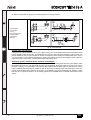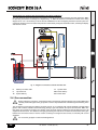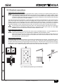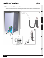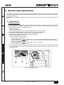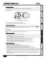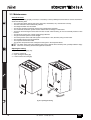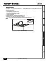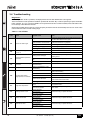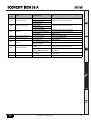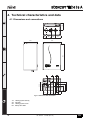
1
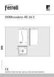
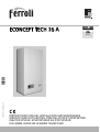
cod. 3540I341 — 04/2008 (Rev. 00)
,
ECONCEPT TECH 35 A
INSTRUCTIONS FOR USE, INSTALLATION AND MAINTENANCE
INSTRUCTIONS D'UTILISATION, D'INSTALLATION ET D'ENTRETIEN
ȅǻǾīǴǼȈ ȋȇdzȈǾȈ, ǼīȀǹȉDZȈȉǹȈǾȈ Ȁǹǿ ȈȊȃȉdzȇǾȈǾȈ
KULLANMA, KURULUM VE BAKøM TALIMATLARø
ECONCEPT TECH 35 A
B
•
•
•
•
•
•
Carefully read the warnings in this instruction booklet since they provide important information on safe
installation, use and maintenance.
This instruction booklet is an integral part of the
product and must be carefully kept by the user for future reference.
If the unit is sold or transferred to another owner or if
it is to be moved, always make sure that the booklet
accompanies the boiler so that it can be consulted
by the new owner and/or installer.
Installation and maintenance must be carried out by
professionally qualified personnel, according to current regulations and the manufacturer's instructions.
Incorrect installation or poor maintenance can cause
damage or physical injury. The manufacturer declines any responsibility for damage caused by errors in installation and use or by failure to follow the
manufacturer's instructions.
Before carrying out any cleaning or maintenance operation, disconnect the unit from the electrical power
supply using the switch and/or the special cut-off devices.
•
•
•
•
•
•
In case the unit breaks down and/or functions poorly,
deactivate it, do not make any attempt to repair it or
directly intervene. Contact professionally qualified
personnel. Any repair/replacement of products must
only be carried out by qualified professional personnel using exclusively genuine parts. Failure to comply with the above could affect the safety of the unit.
Periodical maintenance carried out by qualified personnel is essential for guaranteeing good operation
of the unit.
This unit must only be used for the purpose for which
it was designed. Any other use is considered improper and therefore hazardous.
After removing the packing, check the integrity of the
contents. Packing materials must not be left within
the reach of children as they are potentially hazardous.
In case of doubt do not use the unit, and contact the
supplier.
The images shown in this manual are a simplified
representation of the product. In this representation
there may be slight, unimportant differences with the
supplied product.
B
This symbol indicates "Caution" and is placed next to all safety warnings. Strictly follow
these instructions in order to avoid danger and damage to persons, animals and things.
A
This symbols calls attention to a note or important notice.
Declaration of conformity
Manufacturer: FERROLI S.p.A.
Address: Via Ritonda 78/a 37047 San Bonifacio VR Italy
declares that this unit complies with the following EU directives:
•
•
•
•
Gas Appliance Directive 90/396
Efficiency Directive 92/42
Low Voltage Directive 73/23 (amended by 93/68)
Electromagnetic Compatibility Directive 89/336 (amended by 93/68)
President and Legal Representative
Cav. del Lavoro
Dante Ferroli
2
cod. 3540I341 - 04/2008 (Rev. 00)
EN
ECONCEPT TECH 35 A
1 Operating instructions ............................................................................................................ 4
1.1 Introduction............................................................................................................................................. 4
1.2 Control panel .......................................................................................................................................... 4
1.3 Turning on and off .................................................................................................................................. 6
1.4 Adjustments............................................................................................................................................ 7
2 Installation .............................................................................................................................. 11
2.1 General Instructions ............................................................................................................................. 11
2.2 Place of installation .............................................................................................................................. 11
2.3 Plumbing connections .......................................................................................................................... 11
2.4 Gas connection .................................................................................................................................... 13
2.5 Electrical connections........................................................................................................................... 14
2.6 Fume ducts........................................................................................................................................... 15
2.7 Condensate drain connection............................................................................................................... 19
3 Service and maintenance...................................................................................................... 20
3.1 Adjustments.......................................................................................................................................... 20
3.2 Start-up................................................................................................................................................. 21
3.3 Maintenance ......................................................................................................................................... 22
3.4 Troubleshooting.................................................................................................................................... 24
4 Technical characteristics and data ...................................................................................... 26
4.1 Dimensions and connections ............................................................................................................... 26
4.2 General view and main components .................................................................................................... 27
4.3 Plumbing circuit .................................................................................................................................... 28
4.4 Technical data table ............................................................................................................................. 29
4.5 Diagrams .............................................................................................................................................. 30
4.6 Wiring diagram ..................................................................................................................................... 31
,
cod. 3540I341 - 04/2008 (Rev. 00)
3
ECONCEPT TECH 35 A
1. Operating instructions
1.1 Introduction
Dear Customer,
Thank you for choosing a ECONCEPT TECH 35 A wall-mounted boiler featuring FERROLIadvanced design, cuttingedge technology, high reliability and quality construction. Please read this manual carefully since it provides important
information on safe installation, use and maintenance.
ECONCEPT TECH 35 A is a high-efficiency condensation pre-mixed heat generator with an an airtight chamber for
heating and hot water production (with optional external water heater) with extremely low emissions, running on natural
gas or LPG and equipped with a microprocessor control system.
The boiler shell consists of an aluminium laminar exchanger and a ceramic pre-mixed burner equipped with electronic
ignition and ionization flame control, modulating speed fan and modulating gas valve.
The boiler is arranged for connection to an external storage tank for hot water production (optional). In this manual
all the functions relevant to domestic hot water production are only active with the optional hot water tank connected as
indicated in sec. 2.3.
1.2 Control panel
8
1
2
9
5
15
7
10
eco
comfort
11
reset
12
14
3
4 13
6
fig. 1 - Control panel
Key
1=
2=
3=
DHW temperature setting decrease button
DHW temperature setting increase button
Heating system temperature setting decrease
button
4 = Heating system temperature setting increase
button
5 = Display
6 = Summer/Winter mode selection - Reset button "Sliding Temperature" Menu
7 = Unit On/Off - Economy/Comfort mode selection
button
8 = DHW symbol
9 = DHW circuit operation
10 = Summer mode
11 = Multifunction (blinking during the exchanger protection function)
12 = Eco (Economy) mode
4
13 = Heating operation
14 = Heating symbol
15 = Burner On and actual power (blinking during the
flame protection function)
cod. 3540I341 - 04/2008 (Rev. 00)
EN
ECONCEPT TECH 35 A
Indication during operation
Heating
A heating demand (generated by the Room Thermostat or Remote Timer Control) is indicated by flashing of the hot air
above the radiator (details 13 and 14 - fig. 1).
The display (detail 11 - fig. 1) shows the actual heating delivery temperature and during DHW standby time, the message “d2”.
eco
comfort
eco
comfort
reset
reset
fig. 2
Hot water
A DHW demand (generated by drawing domestic hot water) is indicated by flashing of the hot water under the tap (details 8 and 9 - fig. 1).
The display (detail 11 - fig. 1) shows the actual hot water outlet temperature and, during DHW standby time, the message “d1“.
eco
comfort
eco
comfort
reset
reset
fig. 3
Exclude hot water storage tank (economy)
Hot water storage tank temperature maintaining/heating can be excluded by the user. If excluded, domestic hot water
will not be delivered.
The hot water tank can be deactivated by the user (ECO mode) by pressing the ECO/COMFORT button (detail 7 fig. 1). In ECO mode the display activates the ECO symbol (detail 12 - fig. 1). To activate COMFORT mode, press the
ECO/COMFORT button (detail 7 - fig. 1) again.
EN
cod. 3540I341 - 04/2008 (Rev. 00)
5
ECONCEPT TECH 35 A
1.3 Turning on and off
Boiler lighting
Switch on the power to the unit.
eco
comfort
reset
fig. 4 - Boiler lighting
•
•
•
•
For the following 120 seconds the display will show FH which identifies the heating system air venting cycle.
During the first 5 seconds the display will also show the card software release.
Open the gas cock ahead of the boiler.
When the message FH disappears, the boiler will be ready to operate automatically whenever domestic hot water
is drawn or in case of a room thermostat demand.
Turning the boiler off
Press the button
(detail 7 - fig. 1) for 5 seconds.
eco
comfort
reset
fig. 5 - Turning the boiler off
When the boiler is turned off, the electronic board is still powered.
Domestic hot water and heating operation are disabled. The antifreeze system remains activated.
To relight the boiler, press the button
(detail 7 fig. 1) again for 5 seconds.
eco
comfort
reset
fig. 6
The boiler will be immediately ready to operate whenever domestic hot water is drawn or in case of a room thermostat
demand.
6
cod. 3540I341 - 04/2008 (Rev. 00)
EN
ECONCEPT TECH 35 A
B
The antifreeze system does not work when the power and/or gas to the unit are turned off. To avoid damage
caused by freezing during long idle periods in winter, it is advisable to drain all water from the boiler, DHW
circuit and system; or drain just the DHW circuit and add a suitable antifreeze to the heating system, complying
with that prescribed in sec. 2.3.
1.4 Adjustments
Summer/Winter changeover
Press the button
(detail 6 - fig. 1) for 2 seconds.
eco
comfort
reset
fig. 7
The display activates the Summer symbol (detail 10 - fig. 1): the boiler will only deliver domestic hot water. The antifreeze system remains activated.
To deactivate Summer mode, press the button
(detail 6 - fig. 1) again for 2 seconds.
Heating temperature adjustment
Operate the heating buttons
of 90 °C.
(details 3 and 4 - ) to adjustfig. 1the temperature from a min. of 20 °C to a max.
eco
comfort
reset
fig. 8
Hot water temperature adjustment
Operate the DHW buttons
65°C.
(detail 1 and 2 - fig. 1) to adjust the temperature from a min. of 10°C to a max. of
eco
comfort
reset
fig. 9
EN
cod. 3540I341 - 04/2008 (Rev. 00)
7
ECONCEPT TECH 35 A
Room temperature adjustment (with optional room thermostat)
Using the room thermostat, set the temperature desired in the rooms. If the room thermostat is not installed the boiler
will keep the heating system at its setpoint temperature.
Room temperature adjustment (with optional remote timer control)
Using the remote timer control, set the temperature desired in the rooms. The boiler unit will set the system water according to the required room temperature. For information on the remote timer control, please refer to its user's manual.
Sliding temperature
When the optional external probe is installed the boiler adjustment system works with "Sliding Temperature”. In this
mode, the temperature of the heating system is adjusted according to the outside weather conditions, in order to ensure
high comfort and energy saving throughout the year. As the outside temperature increases, the temperature of the heating system is decreased according to a fixed “compensation curve”.
With Sliding Temperature adjustment, the temperature set with the heating buttons
(details 3 and 4 - fig. 1)
becomes the maximum system delivery temperature. It is advisable to set a maximum value to allow system adjustment
throughout its useful operating range.
The boiler must be adjusted at the time of installation by qualified personnel. Possible adjustments can in any case be
made by the user to improve comfort.
Compensation curve and curve offset
Press the button
(fig. 10).
(detail 6 - fig. 1) for 5 seconds to access the "Sliding temperature" menu; "CU" appears flashing
Operate the DHW buttons
(details 1 and 2 - fig. 1) to adjust the required curve from 1 to 10 according to the
characteristic (fig. 12). By setting the curve to 0, sliding temperature adjustment is disabled.
eco
comfort
reset
fig. 10 - Compensation curve
8
cod. 3540I341 - 04/2008 (Rev. 00)
EN
ECONCEPT TECH 35 A
Press the heating buttons
(fig. 11). Operate the DHW buttons
characteristic (fig. 13).
(details 3 and 4 - fig. 1) to access parallel curve offset; "OF" appears flashing
(details 1 and 2 - fig. 1) to adjust parallel curve offset according to the
eco
comfort
reset
fig. 11 - Parallel curve offset
Press the button
(detail 6 - fig. 1) again for 5 seconds to exit the “Sliding Temperature” menu.
If the room temperature is lower than the required value, it is advisable to set a higher order curve and vice versa. Proceed by increasing or decreasing in steps of one and check the result in the room.
90
85
80
10
9
8
7
6
5
4
70
3
60
2
50
1
40
30
20
20
10
0
-10
-20
fig. 12 - Compensation curves
OFFSET = 20
OFFSET = 40
90
85
80
10
9
8
7
6
5
70
4
60
3
50
2
40
1
30
90
85
80
10
9
8
7
6
5
4
3
70
2
60
1
50
40
30
20
20
20
10
0
-10
-20
20
10
0
-10
-20
fig. 13 - Example of parallel compensation curve shift
Timer Control (optional) is connected to the boiler, the above adjustments are managed accordA IfingthetoRemote
that given in table 1.
EN
cod. 3540I341 - 04/2008 (Rev. 00)
9
ECONCEPT TECH 35 A
Table. 1
Heating temperature adjustment
Adjustment can be made from the Remote Timer Control menu and the boiler
control panel.
DHW temperature adjustment
Adjustment can be made from the Remote Timer Control menu and the boiler
control panel.
Summer/Winter changeover
Summer mode has priority over a possible Remote Timer Control heating
demand.
Eco/Comfort selection
On disabling DHW from the Remote Timer Control menu, the boiler selects
the Economy mode. In this condition, the button
boiler panel is disabled.
(detail 7 - fig. 1) on the
On enabling DHW from the Remote Timer Control menu, the boiler selects
the Comfort mode. In this condition it is possible select one of the two modes
with the button
Sliding Temperature
(detail 7 - fig. 1) on the boiler panel.
Both the Remote Timer Control and the boiler card manage Sliding Temperature adjustment: of the two, the boiler card Sliding Temperature has priority.
Water system pressure adjustment
The filling pressure with system cold, read on the boiler water gauge, must be approx. 1.0 bar. If the system pressure
falls to values below minimum, the boiler card will activate fault F37 (fig. 14).
eco
comfort
reset
fig. 14 - Low system pressure fault
Operate the filling cock (detail 1 - fig. 15) and bring the system pressure to a value above 1.0 bar.
fig. 15 - Filling cock
Once the system pressure is restored, the boiler will activate the 120-second air venting cycle indicated on the
A display by FH.
At the end of the operation always close the filling cock (detail 1 - fig. 15)
10
cod. 3540I341 - 04/2008 (Rev. 00)
EN
ECONCEPT TECH 35 A
2. Installation
2.1 General Instructions
BOILER INSTALLATION MUST ONLY BE PERFORMED BY QUALIFIED PERSONNEL, IN ACCORDANCE WITH
ALL THE INSTRUCTIONS GIVEN IN THIS TECHNICAL MANUAL, THE PROVISIONS OF CURRENT LAW, THE PRESCRIPTIONS OF NATIONAL STANDARDS AND LOCAL REGULATIONS AND THE RULES OF PROPER WORKMANSHIP
2.2 Place of installation
The combustion circuit is sealed with respect to the place of installation, therefore the unit can be installed in any room.
However, the place of installation must be sufficiently ventilated to prevent the creation of any dangerous conditions in
case of even small gas leaks. This safety precaution is required by EEC Directive no. 90/396 for all gas units, including
those with a so-called sealed chamber.
Therefore the place of installation must be free of dust, flammable materials or objects or corrosive gases. The room
must be dry and not subject to freezing.
The boiler is arranged for wall mounting and comes standard with a hooking bracket. The wall fixing must ensure stable
and effective support for the generator.
is enclosed in a cabinet or mounted alongside, a space must be provided for removing the casing
A Ifandtheforunitnormal
maintenance operations
2.3 Plumbing connections
The heating capacity of the unit must be previously established by calculating the building's heat requirement according
to current regulations. The system must be provided with all the components for correct and regular operation. It is advisable to install shut-off valves between the boiler and heating system allowing the boiler to be isolated from the system
if necessary.
B
The safety valve outlet must be connected to a funnel or collection pipe to prevent water spurting onto the floor
in case of overpressure in the heating circuit. If this is not done, and the drain valve trips and floods the room,
the boiler manufacturer is not to be held responsible.
Do not use the water system pipes to earth electrical appliances.
Before installation, carefully flush all the pipes of the system to remove residues or impurities that could impair the operation of the unit.
B
In addition, a filter must be installed on the system return piping to prevent debris or sludge from the system
clogging and damaging the heat generators.
The filter MUST be installed when replacing generators in existing systems. The manufacturer shall not be
held liable for any damage caused to the generator by failure to install or inadequate installation of this filter.
Make the connections to the corresponding connections as shown on the drawing in sec. 4.1 and by the symbols on the
unit.
EN
cod. 3540I341 - 04/2008 (Rev. 00)
11
ECONCEPT TECH 35 A
On request, it is possible to supply the connecting kits shown in the figure below.
A
A - Female sleeve
B - OT 58 nipple
C - O-ring
D - OT 58 clamping ring
E - Copper washer
F - OT 58 fitting
G - Ball cock
A
B
C D E F
G
CD E F
fig. 16 - Connection kits
System water charcteristics
In the presence of water harder than 25° Fr (1°F = 10ppm CaCO3), the use of suitably treated water is advisable in order
to avoid possible scaling in the boiler. The treatment must not in any case reduce the hardness to values below 15°F
(Decree 236/88 for uses of water intended for human consumption). Water treatment is indispensable in the case of
very large systems or with frequent replenishing of water in the system. If partial or total emptying of the system becomes necessary in these cases, it is advisable to refill it with treated water.
Antifreeze system, antifreeze fluids, additives and inhibitors
The boiler is equipped with an antifreeze system that turns on the boiler in heating mode when the system delivery water
temperature falls under 6°C. The device will not come on if the electricity and/or gas supply to the unit are cut off. If it
becomes necessary, it is permissible to use antifreeze fluid, additives and inhibitors only if the manufacturer of these
fluids or additives guarantees they are suitable for this use and cause no damage to the heat exchanger or other components and/or materials of the boiler unit and system. It is prohibited to use generic antifreeze fluid, additives or inhibitors that are not expressly suited for use in heating systems and compatible with the materials of the boiler unit and
system.
12
cod. 3540I341 - 04/2008 (Rev. 00)
EN
ECONCEPT TECH 35 A
Connection to a storage tank for domestic hot water production
The unit's electronic board is arranged for managing an external storage tank for domestic hot water production. Make
the plumbing connections according to the diagram of fig. 17. Make the electrical connections as shown on the wiring
diagram in sec. 4.6. It is necessary to use the kit code 1KWMA11W. At the next lighting, the boiler's control system recognises the presence of the hot water tank probe and automatically configures the DHW function, activating the display
and relevant controls.
8
9
10
11
209
210
fig. 17 - Diagram of connection to external hot water tank
8
9
10
11 System return
209 Boiler delivery
210 Boiler return
Sanitary hot water outlet
Tap water inlet
System delivery
2.4 Gas connection
B
Before making the connection, ensure that the unit is arranged for operation with the type of fuel available and
carefully clean all the pipes of the gas system to remove any residues that could affect good functioning of the
boiler.
The gas must be connected to the relative connector (see fig. 31) in conformity with current standards, with rigid metal
pipes or with continuous flexible s/steel wall tubing, placing a gas cock between the system and the boiler. Make sure
that all the gas connections are tight. The capacity of the gas meter must be sufficient for the simultaneous use of all
equipment connected to it. The diameter of the gas pipe leaving the boiler does not determine the diameter of the pipe
between the unit and the meter; it must be chosen according to its length and loss of head, in conformity with current
standards.
B
EN
Do not use the gas pipes to earth electrical appliances.
cod. 3540I341 - 04/2008 (Rev. 00)
13
ECONCEPT TECH 35 A
2.5 Electrical connections
Connection to the electrical grid
B
The unit's electrical safety is only guaranteed when correctly connected to an efficient earthing system executed according to current safety standards. Have the efficiency and suitability of the earthing system checked
by professionally qualified personnel. The manufacturer is not responsible for any damage caused by failure
to earth the system. Also make sure that the electrical system is adequate for the maximum power absorbed
by the unit, as specified on the boiler dataplate.
The boiler is prewired and provided with a Y-cable and plug for connection to the electricity line. The connections to the
grid must be made with a permanent connection and equipped with a bipolar switch whose contacts have a minimum
opening of at least 3 mm, interposing fuses of max. 3A between the boiler and the line. It is important to respect the
polarities (LINE: brown wire / NEUTRAL: blue wire / EARTH: yellow-green wire) in making connections to the electrical
line. During installation or when changing the power cable, the earth wire must be left 2 cm longer than the others.
B
The user must never change the unit's power cable. If the cable gets damaged, switch off the unit and have it
changed solely by professionally qualified personnel. If changing the electric power cable, use solely “HAR
H05 VV-F” 3x0.75 mm2 cable with a maximum outside diameter of 8 mm.
Room thermostat (optional)
B
CAUTION: The room thermostat must have clean contacts. CONNECTING 230 V. TO THE TERMINALS OF
THE ROOM THERMOSTAT WILL IRREPARABLY DAMAGE THE ELECTRONIC CARD.
When connecting a remote timer control or a timer switch, do not take the power supply for these devices from
their cut-out contacts. Their power supply must be taken with a direct connection from the mains or with batteries, depending on the kind of device.
External probe (optional)
Connect the probe to its respective terminals. The maximum permissible length for the boiler - external probe connection electrical cable is 50 m. A normal 2-wire cable can be used. The external probe should preferably be installed on
the North, North-West wall or that facing the largest area of living room. The probe must never be exposed to the early
morning sun or, insofar as possible, direct sunlight; protect it if necessary. In any case, the probe must not be installed
near windows, doors, ventilation openings, flues or heat sources that could affect the reading.
fig. 18 - External probe positioning not recommended
14
cod. 3540I341 - 04/2008 (Rev. 00)
EN
ECONCEPT TECH 35 A
Access to the electrical terminal board
Follow the instructions given in fig. 19 to access the electrical connection terminal board. The layout of the terminals for
the various connections is given in the wiring diagram in fig. 34.
fig. 19 - Access to the electrical terminal board
2.6 Fume ducts
The unit is “type C” with an airtight chamber and forced draught, the air inlet and fume outlet must be connected to one
of the following extraction/suction systems. The unit is type-approved to work with all the Cxy flue configurations stated
on the technical data plate (some setups are given by way of example in this chapter). It is however possible that some
setups are expressly limited or not permitted by law, standards or local regulations. Before proceeding with installation,
check and meticulously observe the above-mentioned prescriptions. In addition, comply with the provisions concerning
the positioning of wall and/or roof end pieces and the minimum distances from windows, walls, ventilation openings, etc.
B
This C-type unit must be installed using the fume extraction and outlet ducts supplied by the manufacturer in
accordance with UNI-CIG 7129/92. Failure to use them automatically forfeits all warranty and liability of the
manufacturer.
For fume exhaust pipes longer than 1 metre, during installation take in account the natural expansion of the
A materials when the boiler is operating.
To prevent deformations leave an expansion space of approx. 2 ÷ 4 mm for every metre of pipe.
2 ÷ 4 mm
fig. 20 - Expansion
EN
cod. 3540I341 - 04/2008 (Rev. 00)
15
ECONCEPT TECH 35 A
Connection with coaxial pipes
C33
C33
C13
fig. 21 - Examples of connection with coaxial pipes (
C13
C33
C13
= Air /
= Fumes)
Ø 127
Ø 60
Ø 80
120
147
120
142
Ø 60
Ø 100
041002X0
041006X0
Ø 100
For coaxial connection, fit the unit with one of the following starting accessories. For the wall hole dimensions, refer to
sec. 4.1. Any horizontal sections of the fume exhaust must be kept sloping slightly towards the boiler, to prevent possible condensate from flowing back towards the outside and causing dripping.
041001X0
fig. 22 - Starting accessory for coaxial ducts
Before proceeding with installation, check with table 2 that the maximum permissible length is not exceeded, bearing in
mind that every coaxial bend gives rise to the reduction indicated in the table. For example, a Ø 60/100 duct comprising
a 90° bend + 1 horizontal metre has a total equivalent length of 2 metres.
Table. 2 - Max. length coaxial ducts
Max. permissible length
Coaxial 60/100
Coaxial 80/125
5m
15 m
Reduction factor 90° bend
1m
0.5 m
Reduction factor 45° bend
0.5 m
0.25 m
16
cod. 3540I341 - 04/2008 (Rev. 00)
EN
ECONCEPT TECH 35 A
Connection with separate pipes
C53
C33
B23
C53
fig. 23 - Examples of connection with separate pipes (
= Air /
C13
= Fumes)
For connection of the separate ducts, fit the unit with the following starting accessory:
041003X0
fig. 24 - Starting accessory for separate ducts
Before proceeding with installation make sure the maximum permissible length has not been exceeded, by means of a
simple calculation:
1. Completely establish the layout of the system of split flues, including accessories and outlet terminals.
2. Consult the table 4 and identify the losses in meq (equivalent metres) of every component, according to the installation position.
3. Check that the sum total of losses is less than or equal to the maximum permissible length in table 3.
Table. 3 - Max. length separate ducts
Separate ducts
Max. permissible length
EN
55 meq
cod. 3540I341 - 04/2008 (Rev. 00)
17
ECONCEPT TECH 35 A
Table. 4 - Accessories
Losses in meq
Air
inlet
Ø 80
Fume exhaust
Vertical
Horizontal
1.6
2.0
PIPE
1 m M/F
1KWMA83W
1.0
BEND
45° M/F
1KWMA65W
1.2
1.8
90° M/F
1KWMA01W
1.5
2.0
with test point
1KWMA70W
0.3
0.3
air, wall
1KWMA85A
2.0
-
fumes, wall with antiwind
1KWMA86A
-
5.0
Split air/fumes 80/80
1KWMA84U
-
12.0
PIPE SECTION
TERMINAL
FLUE
Connection to collective flues
C43
C83
C43
fig. 25 - Examples of connection to flues (
= Air /
= Fumes)
If you are then going to connect the ECONCEPT TECH 35 A boiler to a collective flue or a single flue with natural
draught, the flue must be expressly designed by professionally qualified technical personnel in conformity with the current standards and be suitable for airtight chamber units equipped with a fan.
In particular, flues must have the following characteristics:
•
•
•
•
•
•
•
•
•
18
Be sized according to the method of calculation stated in the current standards.
Be airtight to the products of combustion, resistant to the fumes and heat and waterproof for the condensate.
Have a circular or quadrangular cross-section, with a vertical progression and with no constrictions.
Have the ducts conveying the hot fumes adequately distanced or isolated from combustible materials.
Be connected to just one unit per floor.
Be connected to just one type of unit (or all and only forced draught units or all and only natural draught units).
Have no mechanical suction devices in the main ducts.
Be at a lower pressure, all along their length, under conditions of stationary operation.
Have at their base a collection chamber for solid materials or condensation equipped with a metal door with an airtight closure.
cod. 3540I341 - 04/2008 (Rev. 00)
EN
ECONCEPT TECH 35 A
2.7 Condensate drain connection
The boiler is equipped with a trap to drain condensate. Fit the inspection connection A and the flexible tube B, pressing
it in about 3 cm and securing it with a clamp. Fill the trap with approx. 0.5 l. of water and connect the flexible tube to the
elimination system.
fig. 26 - Condensate drain connection
EN
cod. 3540I341 - 04/2008 (Rev. 00)
19
ECONCEPT TECH 35 A
3. Service and maintenance
All adjustment, conversion, start-up and maintenance operations described below must only be carried out by Qualified Personnel (meeting the professional technical requirements prescribed by current regulations) such as those of the Local AfterSales Technical Service.
FERROLI declines any liability for damage and/or injury caused by unqualified and unauthorised people tampering with the
unit.
3.1 Adjustments
Gas supply conversion
The unit can operate on Natural Gas or LPG and is factory-set for use with one of these two gases, as clearly shown
on the packing and on the dataplate. Whenever a different gas to that for which the unit is arranged has to be used, a
conversion kit will be required, proceeding as follows:
1.
2.
3.
4.
5.
6.
7.
8.
Remove the casing.
Open the sealed chamber.
Release the fixing clip C and remove the gas pipeA from the fan - venturi assembly.
Replace the nozzle B inserted in the gas pipe with that contained in the conversion kit.
Reassemble the gas pipe A with the clip and check the seal of the connection.
Apply the plate contained in the conversion kit, near the dataplate.
Refit the sealed chamber and casing.
Modify the parameter for the type of gas:
•
•
•
•
•
switch the boiler to standby mode
press the DHW buttons
(detail 1 and 2 - fig. 1) for 10 seconds: the display shows “P01“ flashing.
press the DHW buttons
(details 1 and 2 - fig. 1) to set the parameter 00 (for operation with natural
gas) or 01 (for operation with LPG).
press the DHW buttons
(details 1 and 2 - fig. 1) for 10 seconds.
the boiler will return to the standby mode
9. Using a combustion analyser connected to the boiler fume outlet, check that the CO 2 content in the fumes (with
the boiler operating at max. and min. output) complies with the value given in the technical data table for the corresponding gas type.
fig. 27 - Gas supply conversion
20
cod. 3540I341 - 04/2008 (Rev. 00)
EN
ECONCEPT TECH 35 A
Activating TEST mode
Press the heating buttons
(details 3 and 4 - ) at the same time for 5fig. 1seconds to activate TEST mode.
The boiler lights at the maximum heating power set as described in the following section.
IIIIIIII
IIIIIIII
IIII
The heating symbol (detail 14 - fig. 1) and DHW symbol (detail 8 - fig. 1) flash on the display; the heating power will be
displayed alongside.
IIIII
II I I I
I I I II
I II II I
III III
fig. 28 - TEST mode (heating power = 100%)
To deactivate TEST mode, repeat the activation sequence.
In any case, the TEST mode is disabled automatically after 15 minutes.
Heating power adjustment
To adjust the heating power, switch the boiler to TEST mode (see sec. 3.1). Press the heating buttons
tails 3 and 4 - fig. 1) to increase or decrease the power (min. = 00 - max. = 100). Press the RESET button
seconds; the max. power will remain that just set. Exit TEST mode (see sec. 3.1).
(dewithin 5
3.2 Start-up
B
Checks to be made at first lighting, and after all maintenance operations that involved disconnection from the
systems or an operation on safety devices or parts of the boiler:
Before lighting the boiler
•
•
•
•
•
•
•
•
•
Open any on-off valves between the boiler and the systems.
Check the tightness of the gas system, proceeding with caution and using a soap and water solution to detect any
leaks in connections.
Check correct prefilling of the expansion tank (ref. sec. 4.4).
Fill the water system and make sure all air contained in the boiler and the system has been vented, by opening the
air vent valve on the boiler and any vent valves on the system.
Fill the condensate trap and check correct connection of the condensate elimination system.
Make sure there are no water leaks in the system, DHW circuits, connections or boiler.
Check correct connection of the electrical system and efficiency of the earthing system
Make sure the gas pressure value for heating is that required.
Make sure there are no flammable liquids or materials in the immediate vicinity of the boiler
Checks during operation
•
•
•
•
•
•
•
•
•
•
EN
Turn the unit on as described in sec. 1.3.
Make sure the fuel circuit and water systems are tight.
Check the efficiency of the flue and air-fume ducts while the boiler is working.
Check the correct tightness and functionality of the condensate elimination system and trap.
Make sure the water is circulating properly between the boiler and the systems.
Make sure the gas valve modulates correctly in the heating and domestic hot water production phases.
Check proper boiler lighting by doing several tests, turning it on and off with the room thermostat or remote control.
Using a combustion analyser connected to the boiler fume outlet, check that the CO2 content in the fumes, with the
boiler operating at max. and min. output, corresponds to that given in the technical data table for the corresponding
type of gas.
Make sure the fuel consumption indicated on the meter matches that given in the technical data table on sec. 4.4.
Check the correct programming of the parameters and carry out any necessary customization (compensation curve,
power, temperatures, etc.).
cod. 3540I341 - 04/2008 (Rev. 00)
21
ECONCEPT TECH 35 A
3.3 Maintenance
Periodical check
To keep the unit working properly over time, it is necessary to have qualified personnel make an annual check that includes the following tests:
•
•
•
•
•
•
•
•
•
•
•
•
The control and safety devices (gas valve, flow meter, thermostats, etc.) must function correctly.
The fume extraction circuit must be fully efficient.
The airtight chamber must be sealed
The air-fume end piece and ducts must be free of obstructions and leaks
The condensate evacuation system must be efficient with no leakage or obstructions.
The burner and exchanger must be clean and free of scale. When cleaning, do not use chemical products or wire
brushes.
The electrode must be free of scale and properly positioned.
The gas and water systems must be airtight.
The water pressure in the cold water system must be about 1 bar; otherwise, bring it to that value.
The circulation pump must not be blocked.
The expansion tank must be filled.
The gas flow and pressure must correspond to that given in the respective tables.
The boiler casing, panel and aesthetic parts can be cleaned with a soft damp cloth, possibly soaked in soapy
A water. Do not use any abrasive detergents and solvents.
Opening the casing
To open the boiler casing (fig. 29):
1. Undo the screws (1)
2. Open, turning the casing (2)
3. Lift and remove the casing (3)
3
comeco
fort
re
se
t
1
2
0
comeco
fort
3
BA
re
R
se
4
t
1
2
0
3
BA
R
4
2
1
1
fig. 29 - Opening the casing
22
cod. 3540I341 - 04/2008 (Rev. 00)
EN
ECONCEPT TECH 35 A
Combustion analysis
It is possible to analyse the combustion through the air sampling (detail 2) and fume sampling (detail 1) points shown
in fig. 30.
To take the measurement:
1.
2.
3.
4.
5.
Open the air and fume sampling points
Insert the probes
Press the"+" and "-" buttons for 5 seconds to activate TEST mode
Wait 10 minutes for the boiler to stabilise
Take the measurement
For natural gas the CO2 reading must be between 8.7 and 9 %.
For LPG the CO2 the reading must be between 9.5 and 10 %.
A Analyses made with an unstabilised boiler can cause measurement errors.
2
1
2
1
fig. 30 - Combustion analysis
EN
cod. 3540I341 - 04/2008 (Rev. 00)
23
ECONCEPT TECH 35 A
3.4 Troubleshooting
Diagnostics
In case of operation faults or problems, the display flashes and the fault identification code appears.
There are faults that cause permanent shutdown (marked with the letter “A”): to restore operation just press the RESET
button (detail 8 - fig. 1) for 1 second or RESET on the optional remote timer control if installed; if the boiler fails to start,
it is necessary to first eliminate the fault.
Other faults (marked with the letter “F”) cause temporary shutdowns that are automatically reset as soon as the value
returns within the boiler's normal working range.
Table. 5 - List of faults
Fault
code
A01
A02
A03
Fault
Possible cause
Cure
No gas
Check the regular gas flow to the boiler and that the air
has been eliminated from the pipes
Ignition/detection electrode fault
Check the wiring of the electrode and that it is correctly
positioned and free of any deposits
Faulty gas valve
Check the gas valve and replace it necessary
Insufficient gas supply pressure
Check the gas supply pressure
The burner fails to light
Flame present signal with
burner off
Overtemperature protection
activated
Trap clogged
Check the trap and clean it if necessary
Electrode fault
Check the ionisation electrode wiring
Card fault
Check the card
Heating sensor damaged
Check the correct positioning and operation of the
heating sensor
No water circulation in the system
Check the circulating pump
Air in the system
Vent the system
See fault F07
A04
Fume exhaust duct safety
activated
Fault F07 generated 3 times in
the last 24 hours
A05
Fan protection activated
Fault F15 generated for 1 hour
(consecutive)
Ionisation electrode fault
A06
F07
No flame after ignition
stage (6 times in 4 minutes)
High fume temperature
See fault F15
Check the position of the ionisation electrode and
replace it if necessary
Flame unstable
Check the burner
Gas valve Offset fault
Check the Offset adjustment at minimum power
air/fume ducts obstructed
Remove the obstruction from the flue, fume exhaust
ducts and air inlet and terminals
Trap clogged
Check the trap and clean it if necessary
Flue partially obstructed or insufficient
Check the efficiency of the flue, fume exhaust ducts
and outlet terminal
Fume sensor position
Check the correct positioning and operation of the
fume sensor
Sensor damaged
F10
Delivery sensor 1 fault
Wiring shorted
Check the wiring or replace the sensor
Wiring disconnected
Sensor damaged
F11
Return sensor fault
Wiring shorted
Check the wiring or replace the sensor
Wiring disconnected
Sensor damaged
F12
DHW sensor fault
Wiring shorted
Check the wiring or replace the sensor
Wiring disconnected
24
cod. 3540I341 - 04/2008 (Rev. 00)
EN
ECONCEPT TECH 35 A
Fault
code
Fault
Possible cause
Cure
Sensor damaged
F13
Fume sensor fault
Wiring shorted
Check the wiring or replace the sensor
Wiring disconnected
Sensor damaged
F14
Delivery sensor 2 fault
Wiring shorted
Check the wiring or replace the sensor
Wiring disconnected
No 230V power supply
Check the wiring of the 3-pole connector
F15
Fan fault
Tachometric signal interrupted
Check the wiring of the 5-pole connector
Fan damaged
Check the fan
F34
Supply voltage under 170V
Power supply trouble
Check the electrical system
F35
Mains frequency fault
F37
Incorrect system water
pressure
Power supply trouble
Check the electrical system
Pressure too low
Fill the system
Water pressure switch not connected or damaged
Check the sensor
Probe damaged or wiring
shorted
Check the wiring or replace the sensor
Probe disconnected after activating the sliding temperature
Reconnect the external probe or disable the sliding
temperature
F39
External probe fault
A41
Sensor positioning
Delivery sensor disconnected
from the pipe
Check the correct positioning and operation of the
heating sensor
F42
Heating sensor fault
Sensor damaged
Replace the sensor
EN
cod. 3540I341 - 04/2008 (Rev. 00)
25
ECONCEPT TECH 35 A
4. Technical characteristics and data
195
4.1 Dimensions and connections
76
120
330
134
120
700
450
240
180
6 5
118
229
3
180
1
44
97
74
74
48
83
74
fig. 31 - Dimensions and connections
1=
3=
5=
6=
26
Heating system delivery
Gas inlet
Heating system return
Safety valve drain
cod. 3540I341 - 04/2008 (Rev. 00)
EN
ECONCEPT TECH 35 A
4.2 General view and main components
29
191
5
201
56
16
82
188
22
161
278
19
196
14
186
250
36
193
114
32
95
10 74
209 44 7
210
11
fig. 32 - General view
5
7
10
11
14
16
19
22
29
32
36
44
56
74
82
EN
Airtight chamber
Gas inlet
System delivery
System return
Safety valve
Fan
Combustion chamber
Main burner
Fume outlet manifold
Heating circulator
Automatic air vent
Gas valve
Expansion tank
Heating system cock
Detection electrode
95
114
161
186
188
191
193
196
201
209
210
250
278
cod. 3540I341 - 04/2008 (Rev. 00)
Diverter valve
Water pressure switch
Condensing heat exchanger
Return sensor
Ignition electrode
Fume temperature sensor
Trap
Condensate tray
Mixing chamber
Boiler delivery
Boiler return
System delivery filter
Double sensor (Safety + Heating)
27
ECONCEPT TECH 35 A
4.3 Plumbing circuit
16
161
278
56
196
186
44
114
36
193
250
154
95
32
14
241
74
209
10
210
7
11
fig. 33 - Plumbing circuit
7
10
11
14
16
32
36
44
56
74
95
114
154
161
28
Gas inlet
System delivery
System return
Safety valve
Fan
Heating circulator
Automatic air vent
Gas valve
Expansion tank
Heating system cock
Diverter valve
Water pressure switch
Condensate outlet
Condensing heat exchanger
186
193
196
209
210
210
241
278
cod. 3540I341 - 04/2008 (Rev. 00)
Return sensor
Trap
Condensate tray
Boiler delivery
Boiler return
Boiler return
By-pass
Double sensor (Safety + Heating)
EN
ECONCEPT TECH 35 A
4.4 Technical data table
The column on the right gives the abbreviation used on the dataplate.
Data
Unit
Setting
Max. heating power
kW
34.8
(Q)
Min. heating power
Max. Heat Output in heating (80/60°C)
kW
6.5
(Q)
kW
34.2
(P)
(P)
Min. Heat Output in heating (80/60°C)
kW
6.3
Max. Heat Output in heating (50/30°C)
kW
36.7
Min. Heat Output in heating (50/30°C)
kW
6.9
Max hot water heating power
kW
34.8
Min hot water heating power
kW
6.5
Max hot water heating power
kW
34.2
Min hot water heating power
kW
6.3
mbar
20
Max gas delivery G20
3
m /h
3.68
Min gas delivery G20
3
m /h
0.69
Gas feed pressure G31
Gas feed pressure G20
mbar
37
Max gas delivery G31
kg/h
2.73
Min gas delivery G31
kg/h
0.51
Efficiency class directive 92/42 EEC
-
NOx emission class
-
5
(NOx)
Max working pressure in heating
bar
3
(PMS)
Min working pressure in heating
bar
0.8
°C
95
Heating water content
litres
2
Heating expansion tank capacity
litres
10
bar
1
Max heating temperature
Heating expansion tank pre-filling pressure
Protection class
Supply voltage
IP
V/Hz
X5D
230V/50Hz
Electrical power input
W
140
Electrical power input in hot water production
W
140
Weight with no load
kg
Type of unit
41
C13-C23-C33-C43-C53C63-C83-B23-B33
PIN CE
EN
(tmax)
0063BR3161
cod. 3540I341 - 04/2008 (Rev. 00)
29
ECONCEPT TECH 35 A
4.5 Diagrams
Circulating pumps head/ pressure loss
H [m H2O] 7
3
6
2
5
A
4
1
3
2
1
0
0
500
1.000
1.500
2.000
Q [l/h]
A
Boiler pressure losses
1 - 2 - 3 Circulating pump speed
30
cod. 3540I341 - 04/2008 (Rev. 00)
EN
ECONCEPT TECH 35 A
4.6 Wiring diagram
155
188
10kOhm
1.8kOhm
186
138 256
82
1 2 3 4 5 6
16
L N
230V
50Hz
32
T° T°
16
278
DBM04A
191
44
114
95
72
139
fig. 34 - Wiring diagram
Caution: Before connecting the room thermostat or the remote timer control, remove the jumper on the
A terminal
block.
16
32
44
72
82
95
114
138
139
155
186
EN
Fan
Heating circulator
Gas valve
Room thermostat
Detection electrode
Diverter valve
Water pressure switch
External sensor
Remote timer control
Hot water temperature sensor (optional)
Return sensor
188
191
278
256
cod. 3540I341 - 04/2008 (Rev. 00)
Ignition electrode
Fume temperature sensor
Double sensor (heating + safety)
Modulating heating circulator pump signal
31