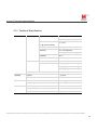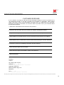
1
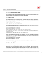
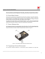
CruizCore® XG1300L USER’S MANUAL
®
The Cruizcore XG1300L
Digital Gyroscope and Accelerometer for the LEGO® MINDSTORMS® NXT
User’s Manual Rev1.1
2013. 05. 20
Copyright© Microinfinity Co., Ltd.
http://www.minfinity.com
EMAIL: [email protected], TEL: +82 31 546 7408 FAX: +82 31 546 7409
Note: This product is not connected to or endorsed by The LEGO Group. LEGO MINDSTORMS are trademarks of
The LEGO Group.
Microinfinity reserves all rights in this document and its subject matter. The recipient acknowledges these rights and assures the use of this document only for the purpose it was delivered.
1
CruizCore® XG1300L USER’S MANUAL
1. Introduction to Inertial Sensors
Inertial sensors are self-contained devices that can measure rates of rotation (gyroscopes) and
linear motion (accelerometers). These devices do not require external signals or references in order
to operate.
1.1 Gyroscopes
A gyroscope (or gyro) is a sensor that can measure rate of rotation about a specific axis. The output
of these devices can be added up (integrated) over time in order to estimate the angle of rotation.
Most common applications use gyros as angle measurement devices.
For example, a robot turning at 30 deg/sec (degrees per second), can make a 180 deg turn in 6
seconds (TIME). If a gyroscope is attached to the robot, at any given time its output will be 30
deg/sec. Suppose that the gyro updates its output 100 times per second (FREQUENCY), the
number of samples (N) that the gyro will output during the 6 second rotation will be:
N = TIME*FREQUENCY = 6*100 = 600
The sampling period (PERIOD) is computed as the inverse of the frequency:
PERIOD = 1/FREQUENCY = 0.01 [seconds]
And the heading angle can be computed by integrating the individual gyro readings as follows:
ANGLE = RATE[0]*PERIOD + RATE[1]*PERIOD + … + RATE[N]*PERIOD
ANGLE = 30*0.01 + 30*0.01 + … + 30*0.01 = 180 [degrees]
In the practice, gyros are affected by several factors such as bias drift, temperature and
acceleration. Suppose now that in our previous example, the contributions of these sources of error
make the gyro output 1% larger than the true rate value, in this case, the estimated angle at the end
of the turn will have an error of about 2 degrees:
ANGLE = 30.3*0.01 + 30.3*0.01 + … + 30.3*0.01 = 181.8 [degrees]
Some errors such as drift will affect the gyro output even if the robot is stationary, and if not taken in
consideration, can create significant errors over time. In mobile robotic applications gyros are
commonly used to determine the robot orientation (or heading), furthermore, the gyro output can be
combined with wheel encoder data in order to estimate the robot position.
1.2 Accelerometers
An accelerometer is a sensor that can measure velocity changes (acceleration) as well as the
gravity acceleration. In theory, after removing the gravity acceleration component, the output of
these sensors could be integrated once to estimate velocity and a second time to estimate position.
In the practice this sensors are also affected by errors and the double integration needed for
estimating position produces unpredictable results within seconds of operation.
The most common use of these sensors is to measure the gravity acceleration component, which in
Microinfinity reserves all rights in this document and its subject matter. The recipient acknowledges these rights and assures the use of this document only for the purpose it was delivered.
2
CruizCore® XG1300L USER’S MANUAL
turn is directly related to the tilt angle of the sensor. A pair of accelerometers mounted on a robot
with the X-axis (ACC_X) pointing towards the side and the Y-axis pointing forward (ACC_Y), can be
used to compute tilt angles (ROLL and PITCH) as follows:
sin(PITCH) = ACC_Y / GRAVITY
sin(ROLL) = ACC_X / (GRAVITY*cos(PITCH))
This solution assumes that the measurements are taken when the robot is either stationary or
moving at constant speed. For small angles the equations can be further simplified as follows:
PITCH = ACC_Y / GRAVITY [radians]
ROLL = ACC_X / GRAVITY [radians]
Another application for accelerometers is as a robot collision detector. A robot hitting an obstacle
will experience large changes in velocity (accelerations) for very short periods of time. These large
accelerations can be used as an indication that the robot hit an obstacle.
2. The CruizCore® XG1300L
The CruizCore® XG1300L is a digital device containing MEMS gyroscope and accelerometer
®
®
®
sensors. This device is compatible with the Lego Mindstorms NXT kit. The CruizCore XG1300L
internally processes the sensor signals eliminating the most significant errors that affect these type
of inertial devices. The sensor outputs from the CruizCore® XG1300L are near-free of errors and
can be used without further processing in many types of applications.
2.1 Sensor Description
The CruizCore® XG1300L contains a single axis MEMS gyroscope. The internal signal processing
applies factory calibrated scale factors, and compensates for the most significant errors that affect
gyroscopes such as changes in bias drift.
The CruizCore® XG1300L internally computes the accumulated angle and makes it available to the
user as an additional measurement. Users interested in measuring angles are encouraged to use
this measurement because of the following reasons:
1. Applications with limited computational resources will not need to integrate the rate
measurements in order to obtain angle information. Furthermore, some applications can
choose a lower update rate of the angle value and still get the maximum accuracy since the
integration is always performed at the maximum update rate (100 Hz). For example, for
position estimation in low dynamic robotic applications, users can use an angle update rate
of 10 Hz without loosing accuracy.
2. The internal angle estimation is the most accurate, because the XG1300L computes it
using full floating point precision.
The XG1300L also includes a three-axis accelerometer. This device can be configured to use one
of the following ranges ±2G, ±4G and ±8G. As in the case of the gyroscopes, these sensors are
factory calibrated.
2.2 Communication Interface
Microinfinity reserves all rights in this document and its subject matter. The recipient acknowledges these rights and assures the use of this document only for the purpose it was delivered.
3
CruizCore® XG1300L USER’S MANUAL
The CruizCore® XG1300L communicates with the Lego ® Mindstorms® NXT using the I2C bus. It
®
®
includes a connector compatible with Lego NXT cables. The CruizCore XG1300L I2C address is
set to 0x02. Sensor data is stored internally in different registers that the NXT can access by
sending read commands to the appropriate registers (see Table 1).
In addition to the register read operations, the CruizCore® XG1300L provides some additional
functions that can be accessed by sending write commands to specific registers as shown in Table
®
Table 1: The CruizCore XG1300L internal registers
REGISTER (Hex value)
Sensor Value
0x42
Accumulated Angle LSB
0x43
Accumulated Angle MSB
0x44
Rate of Turn LSB
0x45
Rate of Turn MSB
0x46
X-Accelerometer LSB
0x47
X-Accelerometer MSB
0x48
Y-Accelerometer LSB
0x49
Y-Accelerometer MSB
0x4A
Z-Accelerometer LSB
0x4B
Z-Accelerometer MSB
2. These functions allow resetting the sensor as well as changing the accelerometers scale factor.
Table 2: The CruizCore® XG1300L special function registers
REGISTER (Hex value)
XG1300L ACTION
0x60
Reset device
0x61
Select ±2G accelerometer range
0x62
Select ±4G accelerometer range
0x63
Select ±8G accelerometer range
Microinfinity reserves all rights in this document and its subject matter. The recipient acknowledges these rights and assures the use of this document only for the purpose it was delivered.
4
CruizCore® XG1300L USER’S MANUAL
2.3 I2C Communication Speed
®
The CruizCore XG1300L has been tested to work reliably using the low speed I2C setting at 9.6
Kbps. Internally the sensor updates the measurement 100 at 100 Hz.
2.4 Scale Factor
®
The inertial sensors in the CruizCore XG1300L are factory calibrated and the measurements
provided in the form of signed short integers (16 bits or two bytes). The two bytes represent the
sensor reading multiplied by a scale factor of 100. The angle and rate outputs can be estimated
using the following equations:
ANGLE = (MSB*256 + LSB) / 100 [degrees]
RATE = (MSB*256 + LSB) / 100 [degrees/second]
For example a two-byte reading from the register 0x42 (LSB and MSB angle bytes) that gives the
byte sequence 0x1D and 0x32, should be interpreted as:
LSB = 0x1D (hexadecimal) = 29 (decimal)
MSB = 0x32 (hexadecimal) = 50 (decimal)
ANGLE = (MSB*256 + LSB) / 100 = (50*256 + 29) / 100 = 128.29 [degrees]
The accelerometer output takes in consideration the accelerometer range (ACC_RANGE) and is
computed as follows:
ACCELERATION = (MSB*256 + LSB) /1000 * ACC_RANGE / 2 [g]
The ACC_RANGE value can be: 2, 4 or 8; corresponding to +/-2G, +/-4G or +/-8G accelerometer
ranges. For example a two-byte reading from the register 0x46 (LSB and MSB X-accelerometer
bytes), with a scale factor set to +/-4G (ACC_RANGE=4) that gives the byte sequence 0x8F and
0x01, should be interpreted as:
LSB = 0x8F (hexadecimal) = 143 (decimal)
MSB = 0x01 (hexadecimal) = 1 (decimal)
ACCELERATION = (MSB*256 + LSB) / 1000 *ACC_RANGE / 2= (1*256 + 143) / 1000 * 4 / 2
= 0.798 [g]
2.5 Static Bias Drift
Static bias drift affects all gyros and is defined as a non-zero output that can be observed when a
®
gyro is stationary. The CruizCore XG1300L estimates this value during startup, this process takes
approximately one second in which the sensor must remain stationary. Failing to observe this
recommendation will produce unreliable results, which are shown as a constant drift on the angle
value when the unit is stationary. Since in many cases the XG1300L sensor will be mechanically
attached to the NXT controller, it is likely that when the power button is pressed the XG1300L will
Microinfinity reserves all rights in this document and its subject matter. The recipient acknowledges these rights and assures the use of this document only for the purpose it was delivered.
5
CruizCore® XG1300L USER’S MANUAL
also move causing it to miscalculate the bias drift value. This effect can be reversed by sending a
reset command to the device as explained in the following section (Device Reset Function section).
2.6 Device Reset Function
During reset, the XG1300L will recomputed the bias drift value, therefore is must remain stationary.
The bias drift value will change randomly over time due to temperature variations, however the
internal algorithm in the XG1300L will compensate for these changes. We strongly recommend
issuing a reset command to the XG1300L at the beginning of the program.
The reset function also resets the accumulate angle value to a zero. Since the accelerometers
measurements are taken with respect to the sensor reference frame (see Sensor Reference Axes
section) the reset function will have no effect in the accelerometer measurements.
2.7 Sensor Reference Axes
The gyroscope sensitive axis is perpendicular to the flatter area of the sensor and pointing down.
The accelerometer X-axis is pointing towards the side of the device, the Y-axis points forward and
away from the sensor connector, and the Z-axis points down as shown in Figure 1.
Figure 1: The CruizCore XGL1300L sensor reference frame
2.8 Programming Tools and Environments
®
The CruizCore XG1300L implements a communication protocol compatible with Lego® NXT,
Microinfinity reserves all rights in this document and its subject matter. The recipient acknowledges these rights and assures the use of this document only for the purpose it was delivered.
6
CruizCore® XG1300L USER’S MANUAL
therefore giving users freedom to work with their favorite programming tools. The CruizCore®
XG1300L has been verified to work reliably with the following programming tools and environments:
-
NXT-G and nxtOsek
Source code and examples for these two environments can be found in our web site at:
http://www.minfinity.com/eng/page.php?Main=1&sub=1&tab=5
-
NXC
Source code and examples can be found in our web site at:
http://www.minfinity.com/eng/page.php?Main=1&sub=1&tab=5
®
The next release of BricxCC and NCB/NXC will provide native support to the CruizCore XG1300L
(thanks to John Hansen). Users may use the test release built from:
http://bricxcc.sourceforge.net/test_releases/
-
RobotC
Support for RobotC has ben added by Xander Soldaat and can be found at:
http://botbench.com/driversuite
-
Lejos
Support for this environment has been contributed by Daniele Benedettelli and is available starting
with LejOS 0.9.x at http://lejos.sourceforge.net/
2.9 Source Code Example
The following program shows all the functions available in the CruizCore®XG1300L. For explanation
purposes we chose the NXC programming language. The program reads and displays the complete
device data packet. Users can reset the device by pressing the left button or change the
accelerometers scale factor by pressing the right button. The angle and rate measurements are
presented in units of hundredths of degrees and hundredths of degrees/second, while the
acceleration measurements are presented in thousands of gravities or mg.
//Define constants
#define XGL_PORT S1
#define XGL_ADDR 0x02
#define XGL_DATA_REG 0x42
#define XGL_RESET_REG 0x60
#define XGL_ACC_SF_REG 0x61
#define XGL_DATA_PACKET 10
#define XGL_COMMAND 2
#define XGL_TIME_OUT 500
//Current accelerometer range value
byte ACC_RANGE=2;
Microinfinity reserves all rights in this document and its subject matter. The recipient acknowledges these rights and assures the use of this document only for the purpose it was delivered.
7
CruizCore® XG1300L USER’S MANUAL
//XGL1300L sensor data packet
struct XGLpacket
{
short mAng;
short mRate;
short mAccX;
short mAccY;
short mAccZ;
};
//Reset XGL1300L sensor
void XglReset()
{
byte cmd[XGL_COMMAND];
byte n_read=0;
ArrayBuild(cmd,XGL_ADDR, XGL_RESET_REG);
while (I2CStatus(XGL_PORT, n_read) == STAT_COMM_PENDING);
I2CWrite(XGL_PORT,0,cmd);
ACC_RANGE=2;
}
//Change scale factor to +/- 2G, 4G or 8g
void XglAccSF()
{
byte cmd[XGL_COMMAND];
byte n_read=0;
ACC_RANGE=(ACC_RANGE==8)?2:ACC_RANGE<<1;
byte register= XGL_ACC_SF_REG+((ACC_RANGE/2)>>1);
ArrayBuild(cmd,XGL_ADDR, register);
while (I2CStatus(XGL_PORT, n_read) == STAT_COMM_PENDING);
I2CWrite(XGL_PORT,0,cmd);
}
//Reads the full packet from XGL1300L
void XglReadPacket(XGLpacket &XglData)
{
byte data[XGL_DATA_PACKET];
byte cmd[XGL_COMMAND];
byte count=XGL_DATA_PACKET;
byte n_read=0;
ArrayBuild(cmd,XGL_ADDR, XGL_DATA_REG);
while (I2CStatus(XGL_PORT, n_read) == STAT_COMM_PENDING);
if (I2CBytes(XGL_PORT, cmd, count, data))
{//Assemble data
XglData.mAng = data[0] + data[1]*256;
XglData.mRate = data[2] + data[3]*256;
XglData.mAccX = (data[4] + data[5]*256)*ACC_RANGE/2;
XglData.mAccY = (data[6] + data[7]*256)*ACC_RANGE/2;
XglData.mAccZ = (data[8] + data[9]*256)*ACC_RANGE/2;
}
}
Microinfinity reserves all rights in this document and its subject matter. The recipient acknowledges these rights and assures the use of this document only for the purpose it was delivered.
8
CruizCore® XG1300L USER’S MANUAL
task main()
{
XGLpacket xgl;
string msg;
ReadButtonType rbArgs;
//Initialize system
SetSensorLowspeed(XGL_PORT);
//Resets sensor and waits for hardware to settle
XglReset();
Wait(XGL_TIME_OUT);
//Main loop
while (1)
{
ClearScreen();
XglReadPacket(xgl);
TextOut(0, LCD_LINE1,"<<RESET SENSOR", false);
//Print sensor data
TextOut(0, LCD_LINE2,"ANGLE:");
NumOut(40, LCD_LINE2,xgl.mAng);
TextOut(0, LCD_LINE3,"RATE:");
NumOut(40, LCD_LINE3,xgl.mRate);
TextOut(0, LCD_LINE5,">>ACC RANGE +/-");
NumOut(92, LCD_LINE5,ACC_RANGE);
TextOut(0, LCD_LINE6,"ACC_X:");
NumOut(40, LCD_LINE6,xgl.mAccX);
TextOut(0, LCD_LINE7,"ACC_Y:");
NumOut(40, LCD_LINE7,xgl.mAccY);
TextOut(0, LCD_LINE8,"ACC_Z:");
NumOut(40, LCD_LINE8,xgl.mAccZ);
//Reset sensor if user presses the left key
rbArgs.Index = BTNLEFT;
SysReadButton(rbArgs);
if (rbArgs.Pressed)
{
XglReset();
TextOut(0, LCD_LINE1,"Resetting Device
Wait(XGL_TIME_OUT);
}
", false);
//Change accelerometer range if user presses the right key
rbArgs.Index = BTNRIGHT;
SysReadButton(rbArgs);
if (rbArgs.Pressed)
{
XglAccSF();
TextOut(0, LCD_LINE5,"Changing Range
",false);
Wait(XGL_TIME_OUT);
}
Wait(100);
}
}
Microinfinity reserves all rights in this document and its subject matter. The recipient acknowledges these rights and assures the use of this document only for the purpose it was delivered.
9
CruizCore® XG1300L USER’S MANUAL
2.10 Technical Specification
Performance
Gyroscope
Input Dynamic Range
± 100 ˚/sec (Continuous)
± 150 ˚/sec (Instantaneous)
Rate Noise
(1σ @ 50Hz bandwidth)
< 0.1 ˚/sec
Scale Factor Error
0.5 % (Typical)
Sensitivity
0.01 ˚/sec/digit (Rate)
0.01 ˚/digit (Accumulated angle)
Accelerometers
Bandwidth
50 Hz
Bias Drift
10 ˚/hr (Typical)
Measurement Range
±2G, ±4G, ±8G(Selectable)
Sensitivity
1 mg/digit (Typical, ±2G setting)
2 mg/digit (Typical, ±4G setting)
3.9 mg/digit (Typical, ±8G setting)
Physical
Electrical
Environmental
Output Update Rate
100Hz
Weight
< 15 grams
Size
48 mm X 32 mm X 21 mm
Power Consumption
< 60mW (@5V)
Input Voltage
3.3 ~ 5.5 V
Operating Temperature
-20 ~ 80 °C
Storage Temperature
-40 ~ 100 °C
Shock
200 gRMS
Microinfinity reserves all rights in this document and its subject matter. The recipient acknowledges these rights and assures the use of this document only for the purpose it was delivered.
10
CruizCore® XG1300L USER’S MANUAL
Contact Information
Corporate Office
Microinfinity Co., Ltd.
8F KANC, 906-10, Iui-dong,
Yeongtong-gu, Suwon-si
Gyeonggi-do, 443-270, Korea
Tel : +82 31 546 7408
Fax : +82 31 546 7409
Email: [email protected]
USA Technical Support
P.O. Box 131284
Ann Arbor, MI 48105, USA
Tel : +1-734-223-5904
Fax : +1-866-400-3125
Email: [email protected]
Homepage: http://www.minfinity.com
Microinfinity reserves all rights in this document and its subject matter. The recipient acknowledges these rights and assures the use of this document only for the purpose it was delivered.
11
CruizCore® XG1300L USER’S MANUAL
CUSTOMER RESPONSE
It is our intention to provide you with the best documentation possible to ensure successful use of
your Microinfinity product. If you wish to provide your comments on organization, clarity, subject
matter, and ways in which our documentation can better serve you, please FAX your comments.
Please list the following information, and use this outline to provide us with your comments about
this manual and product.
1. What are the best features of this document and product?
2. How does this document meet your hardware and software development needs?
3. Do you find the organization of this data sheet easy to follow? If not, why?
4. What additions to the data sheet do you think would enhance the structure and subject?
5. What deletions from the data sheet could be made without affecting the overall usefulness?
6. Is there any incorrect or misleading information (what and where)?
7. How would you improve this document?
8. How would you improve our software, systems, and products?
9. Other Comments?
From: Name
Company
Address
City / State / ZIP / Country
Telephone: (_______) _________ - _________
Application (optional):
Would you like a reply? Y N
Questions:
FAX: (______) _________ - _________
Microinfinity reserves all rights in this document and its subject matter. The recipient acknowledges these rights and assures the use of this document only for the purpose it was delivered.
12