1
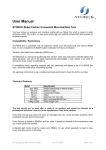
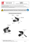
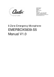
CAVITY FILTER
MOD. 5 KW
USER’S MANUAL
Release 1.0
Mod. 5KW
GENERAL DESCRIPTION
FM double cavity filters made in quarter wave high “Q” with fixed coupling ,
realized in aluminium with internal line in silvered brass and copper .
The resonant cavity filter is used to avoid intermodulation problems that can occur
when several transmitters are located close one to another.
Installed between transmitter and antenna, provide an output free from spurious and
isolation from other transmissions.
The equipments are usually set up in the factory on customer request.
They are otherwise set up at the centre of the frequency range.
TECNICHAL FEATURES
Cavity design
TECNICHAL SPECIFICATION
Input /output connectors
Frequency range
3 dB bandwidth
Power input
Impedance
VSWR
Insertion loss
Dimension
Width
Height
Depth
dB
EIA 7/8”
87.5 ÷ 108 MHz
> 600 Khz
5 Kw
50 Ω
< 1.25
< 0.25 dB
600 mm
1200 mm
300 mm
Band of cavity f ilter MCFDP05 set to 103 M Hz
0
-12
-24
-36
-48
-60
95
99
103
107
111
F(MHz)
dB
Return loss of ca vity filter MCFDP05 set to 103 MHz
0
-6
-12
-18
-24
-30
95
99
103
107
11 1
F(MHz)
INSTALLATION AND USE
To install the cavity filter inserting it between the transmitter and the antenna.
To use a 7/8" cable cellflex of opportune length to connect the transmitter to the
cavity filter,
it is important to insert the inners in correct way.
Even if the cavity filter has been set in factory on the frequency of use, it is essential
however after the transport near the station radio, reset in accurate way.
There are different ways to set the cavity filter among which two ways :
1) To use a tracking generator and an spectrum analyser and to effect all the
necessary regulations to get the least insertion loss in the frequency of use.
(Fig. 1)
2) To connect the filter to the transmitter, before with small power, to insert a
wattmeter between the filter and the anteenna. To set the filter to get the
maximum power of measured output on the wattmeter and the least ROS
measured on the transmitter. (Fig. 2)
SPECTRUM ANALYZER
TRACKING GENERATOR
Fig. 1
ANTE NNA
TRANSMI TTER
WATTMETER
FWD
W
Fig. 2
SWR
In the cavity filter they are only there 4 regulations, 2 stubs and 2 turnable links . The
2 stubs are regulated for centering the frequency of the filter, the 2 links are regulated
for to set the impedance to 50 ohms.
To regulate the stubs, to unscrew the nut of stop ( 1 ) and to rotate the knob ( 2 ).
For regolaree the links, to unscrew under the EIA connector ( 3 ) , to rotate ( 4 ) and
to fix the screw ( 3 ).
Normally after the setting in factory it is not necessary to regulate the links but only
the stubs.
4
3
3
4
2
1