1
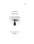
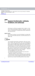
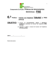
UNIVERSITY OF SURREY
DEPARTMENT OF PHYSICS
Level 1 Laboratory: Classic Experiment C
MEASUREMENT OF THE VELOCITY OF LIGHT
1. AIMS
1.1 Physics
This is one of a set of three “classic” experiments in physics which you will repeat
using modern apparatus. Here, you will measure the velocity of light, c, by using a
modern form of Foucault's rotating mirror method (including a laser as a convenient
bright and highly-directional light beam - not available in Foucault’s day!) With care
in setting up the apparatus, you should be able to achieve a value for c with an overall
error of 5% or less.
1.2 Skills
The particular skills you will start to acquire by performing this experiment are:
•
The ability to follow detailed instructions carefully and in sequence
•
The careful setting up and alignment of optical equipment, including the
use of polarising filters to control image brightness
•
Use of a measuring microscope to record small deflections
•
Researching the historical background of this experiment
•
Calculation and error assessment
IMPORTANT NOTES
This experiment uses a laser as the light source. Although the laser is of low
power it is essential to observe the usual precautions: never look into the
unattenuated laser beam, either directly or via reflection ; ensure that the laser
beam does not traverse an area where someone might accidentally look into it.
Of all Level 1 experiments, this one repays care in setting up and aligning the
apparatus, and attention to points such as cleaning up the image and
compensating for backlash in the micrometer, by yielding improved accuracy.
Last updated Nov 2007 by TJCH
Page 1 of 12
2. INTRODUCTION
The speed of light is one of the most important and intriguing constants of nature.
Whether the light comes from a laboratory laser or from a star hurtling away from the
Earth at a fantastic speed, the measured speed of light c (in vacuo) is always the same.
It is independent of the relative velocities of the light source and the observer.
Einstein, in his Special Theory of Relativity, suggested that the speed of light was
critically important in some surprising ways. In particular:
(i)
(ii)
It establishes an upper limit to the velocity that may be imparted to an object.
Objects moving at close to the speed of light follow a set of physical laws
drastically different from Newton's Laws - and most people's intuition!
Through most of history, those few people who thought about the speed of light
considered it to be infinite. One of the first scientists to question this assumption was
the Italian physicist Galileo, who in 1667 attempted to measure c.[1,2] Galileo was
only able to show that c was far greater than his technique could measure. The time
taken to stop and start the light beam (in his case the reaction times of the
experimenters), was much larger than the transit times of the beam. Most subsequent
attempts to determine c have worked by rapidly "chopping" the beam using rotating
toothed wheels, spinning mirrors or prisms, Kerr cells etc.[1]
The method you are going to use is a modification of the spinning mirror method
originally devised by the French physicist J.J. Foucault in 1860. It has been updated
by the inclusion of a laser as a light source and a modern high speed mirror.
The basic arrangement is shown below in Figure 1.[3]
Fm
Rm
Figure 1:
Schematic Diagram of the Apparatus.
The light from the laser is directed onto a rotating mirror Rm, from which it is reflected
to a fixed mirror Fm a few metres away. On its return path the light again strikes Rm,
which has by now turned through a small angle, so that the final image at s' will be
slightly displaced, by an amount which depends upon the geometry of the apparatus,
the angular velocity of Rm, and the transit time of the light between Rm and Fm. Hence,
by measuring the displacement of the returned beam, the speed of light can be found.
Page 2 of 12
3. DESCRIPTION OF THE APPARATUS
Figure 2 below shows the components of the Pasco speed of light kit.[3] Before
proceeding further, identify all of these in the provided kit, and read the text below.
Figure 2: The Pasco Components.
3.1 The rotating mirror
(Do not attempt to run the motor at this stage)
This mirror, Rm , comes with its own control box. The mirror is flat to within ¼ of the
laser wavelength, and spins in high speed bearings up to a maximum of about 1500
revolutions per second.
The power supply and mirror mounting incorporate an optical pick-up and digital
display which indicates the rotation speed to within 0.1%. The direction of rotation is
reversible and continually variable up to 1000Hz, while a MAX REV button permits
temporary speed increase to about 1500Hz.
The rotating mirror motor assembly may have a plastic screw which locks the motor
pulley in place – this should be loose (or removed) so that the mirror is free to rotate.
3.2 The measuring microscope
A ×90 microscope mounted on a micrometer stage allows precise measurement of the
image displacement. Fine cross hairs in the field of view, which can be focussed by
sliding the eyepiece tube up or down, in conjunction with the micrometer, permit
displacement to be resolved to within ±0.005mm.
Page 3 of 12
The microscope stage also contains a partially-silvered mirror which both reflects and
transmits, called a beam splitter. By positioning the side adjusting lever, the beam
splitter can be oriented at an angle of 45° to the light reflected back from the rotating
mirror, so that the image is correctly reflected directly up into the microscope (see
Fig. 1)
3.2 The fixed mirror
The mirror Fm is front silvered and is mounted on a stand provided with x and y
alignment screws. The stand can be fixed to the bench with a “G-clamp”.
3.3 Optical bench
A 1m optical bench provides a flat and level surface for aligning the optical
components. The rear raised edge of the bench is used to assist alignment.
3.4 Laser
This is a 0.5mW helium-neon laser with output in the red at a wavelength of 632.8nm,
and attaches magnetically to the optical bench.
3.5 Alignment jigs and component holders
These also attach magnetically to the optical bench. The component holders allow the
mounting and alignment of the lenses and polarisers.
Page 4 of 12
4. THEORY
To understand the theory of this experiment it helps to simplify Fig. 1, exaggerate the
angles, and change the distance scales, as shown in Figure 3 below.
Fm
δθ
D
1
2
1'
∆S
2δθ
2δθ
2
δs
1
2'
Figure 3:
s
Plane of
final image
Rm
F'm
1
L2
Simplified optical path
First consider that the rotating mirror Rm is stationary at some angle which sends the
beam to a particular spot on the fixed mirror Fm. Call this beam 1. The fixed mirror
Fm then reflects beam 1 back along its original path - towards Rm (a total round-trip
distance of 2D) and thence back the plane of the final image s. Now let Rm be
continuously rotating counter-clockwise, at angular frequency ω. Note this will cause
the reflected laser beam to be spread out into a “fan” of beams lying in the plane of
the original rays. One of these beams, however (corresponding to the same angle of
Rm when it was fixed) will follow the original path of ray 1 and still strike the same
point on Fm , and be reflected back along its original path towards Rm. However,
meanwhile Rm has now turned through a small angle δθ. This will cause beam 1
returning back from Fm and reflecting off Rm to be deflected, also counter-clockwise,
but by twice this angle, 2δθ. This deflected beam, ray 2 - the dashed arrows in Fig. 3
– will be focussed by lens L2 to a different spot in the plane of the final image, which
is displaced from its original position by an amount δs, say.
However, it helps to consider the whole optical path as a straight line. We do this by
extending rays 1 and 2 backwards beyond Rm to the virtual image of Fm, i.e. F’m
(which is still a distance D away from Rm - see the dotted lines to the left in Fig. 3.)
We now see that, as far as lens L2 is concerned, ray 2 appears to be coming from a
different spot on F’m, which is displaced from its original position by an amount ∆S,
say. Since D is in reality a large distance, ∆S is given by :
∆S = D (2δθ )
Page 5 of 12
(1)
We can now imagine that ∆S represents the size of an object in the plane of F’m that is
imaged by lens L2 to a final image of size δs (which is actually in the plane of the
cross hairs – the interposed beam splitter is omitted in Fig. 3). By applying the simple
thin lens formula, this final image will be of size equal to ∆S de-magnified by a factor
equal to the ratio of the image and object distances of lens L2, i.e. A / (B+D). Thus, δs
is given by :
δs =
A
2 D δθ
( B + D)
(2)
Now, δθ is the angle through which the mirror rotates (at angular velocity ω) in the
time it takes for light to make the round-trip between Rm and Fm (which is 2D/c), i.e. :
δθ =
2D
ω
c
(3)
Combining equations (2) and (3) we then obtain:
δs =
A
4 D 2ω
×
(B + D )
c
(4)
Finally, consider what would happen to the final image if the mirror were rotating
clockwise instead. Then the displaced spot would be not be above ray 1 in the plane
of the final image in Fig. 3, but below. Thus, if we change the rate of rotation of
mirror Rm from f1 Hz clockwise to f2 counter-clockwise (where ω = 2πf ), the total
distance δstot between these two extreme displaced spots may then be written from
Equ. (4) as :
δs tot =
8πAD 2 ( f 1 + f 2 )
(B + D ) c
Page 6 of 12
(5)
5. ALIGNMENT PROCEDURE
N.B. Proper alignment is critical, not only for getting good results, but for getting
any results at all. So follow the procedure below carefully and fully. Do not rush.
Figure 4 below shows the general arrangement of the components. All components, as
they are mounted on the bench, should be pushed back flush against the rear rail of
the bench, thus ensuring that they are at right angles to the axis of the beam.
Rm
Figure 4:
General arrangement of optical bench components.
Check that the bench is on a flat and level surface and that the rotating mirror
assembly and laser are mounted at opposite ends of the bench. Align the front edge of
the rotating-mirror mounting with the 17cm mark on the bench.
5.1 Laser alignment
Place the two alignment jigs at opposite ends of the bench, as shown in Figure 5.
Rm
Figure 5:
Positioning the alignment jigs to align the laser.
Turn on the laser and ensure that the beam block at the top/front of the laser is fully
opened. Adjust the front end of the laser so that the beam passes through the hole in
the first, nearest, alignment jig. To adjust the vertical aim of the laser, use the front
levelling screws. If it is necessary to adjust the beam horizontally, slide the front of
the laser slightly sideways on the bench.
In a similar fashion, next adjust the rear end of the laser so that the beam passes
through the second, farthest, alignment jig.
Page 7 of 12
5.2 Rotating mirror alignment check
The rotating mirror motor assembly may have a plastic locking-screw in place against
the motor pulley – check that this is loose (or removed). The rotating mirror Rm
should have its axis of rotation vertical and perpendicular to the beam. To check this,
remove the alignment jig nearer the mirror and rotate the mirror (make sure that you
are using its reflecting side) to check that the beam reflects back to a spot at the same
height as the hole in the first jig near the laser. If it is slightly too low, for example,
you can use thin paper as shims under the front of the mirror mounting (near the 17cm
mark) to raise the reflected beam to the same height as the hole in the jig, as shown
schematically below in Figure 6.
Figure 6:
Rotating Mirror Alignment
5.3 Lens mounting
Remove the remaining alignment jig and mount the 48mm focal length lens (L1) so
that the centre line of the component holder lines up with 93.0cm mark on the optical
bench (see Fig. 4).
Without moving the holder, slide the lens vertically or horizontally on the holder as
necessary to centre the beam on the rotating mirror Rm. Note that the beam is now
spread out to cover most of this mirror.
Now mount the 252mm focal length lens (L2) with its holder lined up with the 62.2cm
mark (see Fig. 4). Adjust this lens, as for L1, so that the beam is again centred on Rm.
5.4 Mounting the microscope
Place the microscope on the optical bench so that the left hand edge of its mounting
stage is aligned with the 82.0cm mark (see Fig. 4). Turn the beam splitter lever so
that the partially-silvered beam splitter mirror is at 45° to the beam – see Fig. 1 and
note the orientation of beam splitter : it should direct the beam reflected from Rm up
into the microscope. Caution : do not look through the microscope at this stage.
Since inserting the beam splitter may slightly deflect the beam, re-adjust L2 if
necessary to centre the beam back onto Rm.
Page 8 of 12
5.5 Adjusting the fixed mirror
Place the fixed mirror Fm at about 3 to 4 m from Rm as shown below in Figure 7.
Fm
Rm
Figure 7:
Positioning the Fixed Mirror
The angle between the bench axis and the line from rotating to fixed mirrors should
be about 10 -12°.
Turn Rm so that the main (i.e. brightest) laser spot hits Fm near its centre. (A piece of
paper just in front of Fm makes it easier to see the spot). Ignore any other, weaker,
spots which can arise from extraneous multiple reflections from the glass window of
the rotating mirror protective housing, the lenses and other optical components.
Keeping the paper over Fm , slide L2 backwards and forwards along the bench to focus
the spot to the smallest possible point on the fixed mirror. Two people are necessary
for this adjustment, one adjusting L2 and the other observing the sharpness of the spot.
Then, clamp Fm to the bench and carefully use the x and y adjustment screws on the
back of Fm to adjust the reflected beam so that it returns to Rm and strikes it centrally.
Again, two people are needed.
5.6 Focusing the microscope
Place the two polarisers, both attached to opposite sides of a single component holder,
between the laser and the microscope (see Fig. 4), having first set them so that their
axes are “crossed” – i.e. at right angles to each other, so that almost no light can pass
through them. The purpose of the polarisers is to dim the laser light to an acceptable
level so that it can be viewed comfortably through the microscope. With the polarisers
crossed, it is now ok to look into the microscope. Now, carefully rotate one polariser
until the image in the microscope brightens enough to view clearly. Do not rotate the
polariser axes so that they are completely parallel to each other, or remove the
polarisers, while looking through the microscope (until the mirror is rotating – see
section 6B later) as the laser beam will become too bright to view comfortably.
Page 9 of 12
Focus on the cross hairs of the microscope, and then focus the whole instrument by
carefully sliding it up or down in its mounting tube (not forgetting to loosen its
locking-screw first). If the equipment is properly aligned you will see a point image a spot. It is important to get this as sharp as possible.
Note that, in addition to the desired spot image, you may also see other images, due,
for example, to reflections of the laser beam from L1. To make sure that you are
viewing the correct image, block the beam between Rm to Fm. If the spot you are
looking at in the microscope does not disappear, it is not the right image.
5.7 Cleaning up the image
In addition to the desired spot image you may also see interference fringes - these
should cause no problems as long as the spot is clear and sharp, but they can
sometimes be removed by slightly twisting the mounting of L2 so that it is no longer
exactly at right angles to the axis of the beam.
5.8 What to do if you can not find the spot image?
Try varying the tilt of the beam splitter, using the lever, by a few degrees.
Try turning the micrometer knob to bring the image into the field of view.
Try sliding the microscope mount a cm or so in either direction along the bench.
Make sure that the mounting remains flush with the rear fence.
If these minor adjustments don’t work re-check that : the spot on Fm is as sharply
focussed as you can get it (by sliding the position of L2 backwards and forwards along
the bench) ; that the beam reflected back from Fm strikes Rm as centrally as you can
get it (by adjusting the x and y adjustment screws on the back of Fm.)
If none of this helps, the initial alignment is probably not good enough and you had
best start again from the beginning of section 5.
5.9 Component placement – summary
As a final reminder, Fig. 4 shows the approximate positions of the components on the
optical bench when the set-up is complete.
Page 10 of 12
6. MAKING THE MEASUREMENT
A
With the apparatus aligned, and the spot image in sharp focus in the
microscope, viewed roughly centrally on the cross-hairs, set the direction
switch on the rotating mirror control box to clockwise (CW) and switch on the
motor. Allow the mirror to warm up at about 600Hz for about 3 minutes.
B
While the motor is warming up observe the image in the microscope. The spot
image should still be clear but will have also gone dimmer – therefore,
carefully lift off the polarisers to allow more light through the system.(*)
C
Slowly increase the speed of rotation and note how the spot deflection
increases (since Rm now turns through a larger angle during the time it takes
for the light to travel from Rm to Fm and back).
D
Turn the ADJUST knob to bring the rotational speed up to about 1000Hz, then
push the MAX REV button and hold it down. The speed should now increase
to around 1500Hz. As soon as the speed is steady, record its value f1 and adjust
the micrometer to centre the spot image on the cross hairs. Turn off the motor
and carefully note the micrometer reading.
Important Notes
(1)
Never hold the MAX REV button down for more than a minute at a
time, or the motor may overheat.
(2)
When adjusting the micrometer screw, always approach the final
setting from the same direction to eliminate backlash in the mechanical
system. i.e. if you go past the correct setting of the cross hairs, wind
the screw back well back beyond the other side of the spot image and
re-approach in the original direction.
E
With Rm stationary, reverse the rotation direction switch to counter-clockwise
(CCW) and repeat step D. Hence, find the total deflection of the image at s,
δstot , as f is changed from f1 CW to f2 CCW.
F
Record all of the dimensions of the apparatus shown in Figs. 3 and 7, i.e. :
A = distance from :
B =
"
"
D =
"
"
G
(*)
L1 to L2 , minus the focal length of L1
L2 to Rm
Rm to Fm
Substitute your data into Equ. (5) and calculate c. Try to obtain about 3-4 sets
of measurements of δstot and f , and find the mean value for the speed of light.
When the motor is running the spot may become slightly more “smeared”, but should still be
quite distinct. However, if the spot disappears, then switch the motor off, wait for Rm to stop,
re-align it to aim the beam back onto Fm, and return to section 5.8 to re-check the alignment.
Page 11 of 12
H
Carefully assess the error in your measurement. What is the most significant
source of uncertainty? Discuss with a demonstrator how you might set up the
experiment to reduce this error. If time permits this may be tried out!
I
Look up the details of Michelson's rotating prism method for determining c
and comment on why such a technique is inherently superior to that of
Foucault.
7. REFERENCES
[1]
R.S. Longhurst, Geometrical and Physical Optics, Longman (3rd Edition,
1973).
[2]
H.C. Ohanian, Physics, W.W. Norton & Company (2nd Edition, 1989) p.873.
[3]
Pasco Scientific, user manual for the Foucault Method Speed of Light
Apparatus, models OS-9261, 9262 and 9263A.
Page 12 of 12