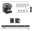
1
dal 1905 manuale tecnico d’uso - technical manual Congratulations, you have chosen an unique in its kind machine. Read carefully what is advised in the instruction manual for “setting-up” of your You will see how easy it is to make delicious coffee and creamy cappuccinos. With the passing of time, you will also realise how little maintenance is needed. . Victoria Arduino EN 43 EN 44 2 gruoups - Net weight: 84 Kg - Gross weight: 90 Kg - Thermal power: 4500 W - Boiler capacity 14 lt - Volts 230-380V 50/60Hz Model: 3 gruoups - Net weight: 98 Kg - Gross weight: 108 Kg - Thermal power: 5000 W - Boiler capacity 17 lt - Volts 230-380V 50/60Hz EN Model: The approval mark certifies that all machines have been subjected to accurate inspection tests and checks 45 INDEX EN 46 TECHNICAL CHARACTERISTICS....................... 45 1. GENERAL REMARKS ON THE CONSIGNMENT........................................... 47 1.1 SAFETY REGULATIONS..................................................................... 47 2. DESCRIPTION...................................................... 51 2.1 ACCESSORIES LIST.......................................................................... 52 3. TRANSPORT AND HANDLING............................ 53 3.1 APPLIANCE IDENTIFICATION............................................................ 53 4. INSTALLATION AND PRELIMINARY OPERATIONS....................................................... 54 5. ADJUSTMENTS TO BE MADE BY A QUALIFIED TECHNICIAN ONLY....................... 56 5.1 FILLING BOILER MANUALLY.............................................................. 56 5.2 PRESSOSTAT / PUMP ADJUSTMENT................................................. 57 5.3 HOT WATER ECONOMISER ADJUSTMENT....................................... 58 5.4 CLOCK BATTERY REPLACEMENT..............................................................59 6. USE....................................................................... 60 6.1 TURNING THE MACHINE ON............................................................. 60 6.2 LED SWITCH ON .............................................................................. 62 6.3 BUTTONS KEY (Selection Configuration).............................................. 62 6.4 STEAM FLOW ADJUSTMENT............................................................. 62 6.4 ADJUSTING THE TURBOCREAM NOZZLE (If Fitted)........................... 63 6.4 ADJUSTING THE AUTOSTEAM NOZZLE (If Fitted).............................. 63 7. PROGRAMMING................................................... 65 7.1 KEY.................................................................................................... 65 7.2 PROGRAMMING (USER Mode).....................................................................65 7.3 PROGRAMMING (technician Mode)........................................................67 8. CLEANING AND MAINTENANCE........................ 79 8.1 SWITCHING OFF THE MACHINE....................................................... 79 8.2 CLEANING THE OUTSIDE OF THE MACHINE.................................... 79 8.3 CLEANING THE STAINLESS COFFEE-HOLDERS............................... 79 8.4 CLEANING THE UNIT WITH THE AID OF THE BLIND FILTER............. 80 8.5 CLEANING FILTERS AND FILTER-HOLDERS..................................... 80 9. MACHINE FUNCTION MESSAGES..................... 81 1. GENERAL REMARKS ON THE CONSIGNMENT 1.1 SAFETY REGULATIONS 1 The present manual is an integral and essential part of the product and will have to be handed over to the user. Read carefully the written warnings in the present manual as they give important suggestions concerning the safety of installation and set-up, use and maintenance. Keep this manual in a safe place for further information. POLLUTION DANGER 2 After removing the packaging, check the integral data of the plate correspond to those of the electrical distribution network. The plate is located under the machine’s base. The installation has to be carried out in compliance with the regulations of the Country where the machine is set-up, according to the instructions by the manufacturer and qualified personnel. The manufacturer can’t be considered responsible for possible damage caused by failure in earthing the plant. For the electrical safety of this machine it is obligatory to arrange the earthing plant, contact an electrician with proper and certified technical suitability, to check the electrical capacity of the plant is adequate to the maximum power of the machine, stated on the plate. In particular the electrician will have to make sure that the section of the plants’ cables is suitable to the power absorbed by the machine. The use of adaptors, multi-sockets and extensions is forbidden. If their use is necessary, it is compulsory to call a licensed electrician. 4 When installing the device, it is necessary to use the parts and materials supplied with the device itself. Should it be necessary to use other parts, the installation engineer needs to check their suitability for use in contact with water for human consumption. 4 bis This machine must be installed according to the applicable federal, state, and local standards (codes) in force with regard to plumbing systems including backflow prevention devices. For this reason, the plumbing connections must be carried out by a qualified technician. ❺ The device needs to be supplied with water that is suitable for human consumption and compliant with the regulations in force in the place of installation. The installation engineer needs confirmation from the owner/manager of the system that the water complies with the requirements and standards stated above. EN parts of the machine are intact. If in doubt, do not use the machine and contact the professionally qualified personnel. The elements of the packaging must be kept out of children’s reach as they can be potential sources of danger and they mustn’t be disposed of in the environment. 3 Before connecting the machine, make sure that the 47 ❻ This machine will have to be used only for the purpose described in this manual. The manufacturer can’t be considered responsible for possible damage caused by improper, wrong, or unreasonable uses. WARNING Before using the machine read carefully and completely the instruction manual, safety regulations and the machine tuning/ directions. ❼ This appliance is not suitable for use by children or EN persons with reduced physical, sensory or mental capabilities, or by persons with a lack of experience or knowledge, unless supervised or given instructions. ➑ The maximum and minimum storage temperatures must fall within a range of [-5, +50]°C. ❽ bisThe operating temperature must be within the range of [+5, +35]°C. 48 ❾ At the end of installation, the device is switched on and taken to rated operating conditions, leaving it in a state in which it is “ready for operation”. The device is then switched off and the whole hydraulic circuit is bled of the first lot of water in order to remove any initial impurities. The device is then refilled and taken to rated operating conditions. After reaching the “ready for operation” condition, the following dispensing operations are carried out: - 100% of the coffee circuit through the coffee dispenser (for more than one dispenser, this is divided equally); - 100% of the hot water circuit through the water dispenser (for more than one dispenser, this is divided equally); - opening of each steam outlet for 1 minute. At the end of installation, it is good practice to draw up a report of the operations. ❿ The use of any electrical device must comply with fundamental regulations. In particular: • do not touch the machine with wet hands or feet; • do not use the machine barefoot; • do not use extensions in places used as a bath or shower; • do not pull the supply cable, to disconnect the machine from the supplying net; • do not leave the machine exposed to atmospheric agents (rain, sun, etc); • do not allow the machine to be used by children or by non-authorised personnel that haven’t read and understood this manual. • During installation, the mains power system needs to be equipped with a disconnector switch to cut off each phase. ⓫ The authorised technician has to, before carrying out any maintenance operation, unplug the socket after having switched off the machine switch. ⓫ bis For the cleaning operations bring the machine to energetic state “O”, that is to say “machine is switched off and socket unplugged” and keep exclusively to what is stated in the present manual. ⓬ In case of breakdown or wrong functioning of the machine, switch it off. Any intervention is strictly forbidden. Contact exclusively professionally authorised personnel. The possible repair of the products will have to be made by the manufacturer only or by an authorised service using exclusively original spare parts. Non-compliance with the above stated can compromise the safety of the machine. ⓯ In the event that you decide not to use a machine of this kind anymore, we advise you make it ineffective by unplugging the socket, then cut the supply cable. ⓭ When setting it up, the licensed electrician will have to check an omni-polar switch is provided by the actual safety regulations with opening distance from the contacts the same or bigger than 3 mm. ⓰ To help the aeration of the machine place it 15 cm from the walls or from other machines on the aeration side. ⓮ To avoid dangerous overheating, we do recommend you uncoil the supply cable to its full length. Do not dispose of the machine in the environment: for waste disposal, contact a specialised authorised centre or contact the manufacturer that will give you information about this. warning danger of burning ⓱ When using the vapour spear, pay much attention and do not place hands under it and do not touch it immediately after its use. ⓲ Remember that before carrying out any set-up oper- ation, maintenance, download, or tuning, the qualified operator has to wear working gloves and safety shoes. ⓴ If the pipe connecting to the mains water is replaced the old pipe must never be re-used. warning INFORMATION TO THE USERS Under the senses of art. 13 of Law Decree 25th July 2005, n. 151 “Implementation of the Directives/ Guidelines 2002/95/CE, 2002/96/CE and 2003/108/CE, concerning the reduction of the use of dangerous substances in electric and electronic equipment, as well as the disposal of wastes“. The symbol of the crossed large rubbish container that is present on the machine points out that the product at the end of its life cycle must be collected separately from the other wastes. The user for this reason will have EN ⓮ bis The user mustn’t replace the supply cable of this machine. In case of damage, switch the machine off and for its replacement contact exclusively professionally qualified personnel. warning danger of pollution ⓳ The maximum noise disturbance level is lower than 70db. 49 EN to give the equipment that got to its life cycle to the suitable separate waste collection centres of electronic and electrotechnical wastes, or to give it back to the seller or dealer when buying a new equipment of equivalent type, in terms of one to one. The suitable separate waste collection for the following sending of the disused equipment to recycling, the dealing or handling and compatible environment disposal contributes to avoid possible negative effects on the environment and on the people’s health and helps the recycling of the materials the machine is composed of. The user’s illegal disposal of the product implies the application of administrative fines as stated in Law Decree n.22/1997” (article 50 and followings of the Law Decree n.22/1997). 50 2. DESCRIPTION Delivery Unit Buttons LCD Display Electric Cup-Warmer Select Buttons Hot Water / Steam Programming Keys Adjustment Dial Steam Flow Delivery Unit Manual Steam Nozzle Filter-Holder Hot Water Nozzle Cup Rack Autosteam Nozzle Drip Tray Machine Main Switch EN Piede Regolabile Fig. 1 51 2.1 ACCESSORIES LIST A12 A10 A05 A11 CODE A02 A01 A04 A07 EN 52 A13 A08 A09 3 GROUPS 1 1 1 1 A03 3 4 A04 Double filter 2 3 A05 Single filter 1 1 A06 Blind filter 1 1 A07 Spring 3 4 A08 Double delivery spout 2 3 A09 Single delivery spout 1 1 A10 A11 Coffee presser 1 1 Microfibre cloth 1 1 A12 DVD 1 1 A13 Overall 1 1 A02 A06 A03 2 GROUPS Filling tube ⅜” Worktop draining tube Ø 25 mm - l. 150 cm Filter-holder A01 Fig. 2 DESCRIPTION 3. TRANSPORT AND HANDLING 3.1 APPLIANCE IDENTIFICATION When contacting the manufacturer, Victoria Arduino for any reason, always quote the machine serial number. The machine is transported on pallets containing several machines inside boxes secured to the pallet by straps. Before performing any transport or handling operation, the operator must: • wear safety gloves and footwear and overalls with elasticised ends. Pallets must be transported using an adequate lifting mechanism (fork-lift truck type). During the entire handling operation, the operator must make sure no one or nothing is inside the operating area. Slowly lift the pallet to about 30 cm from the ground and move to the loading area. After making sure there are no CAUTION: POLLUTION HAZARD Once the machine has been freed of the pallet or container, do not discard these in the environment - pollution hazard. CAUTION: COLLISION OR CRUSHING HAZARD Before performing the following operation, make sure the load is in place and is not likely to fall when the straps are cut. The operator, wearing safety gloves and footwear, must now cut the straps and store the product. To perform this operation, check the technical characteristics of the product to determine the weight of the machine to be stored and take consequent precautions. EN CAUTION: COLLISION OR CRUSHING HAZARD obstacles, persons or things, proceed with loading. Once at destination, always using an adequate lifting mechanism (eg. fork-lift), after making sure there is no one or nothing within the unloading area, lower the pallet to about 30 cm from the ground and transport it to the storage area. 53 4. INSTALLATION AND PRELIMINARY OPERATIONS EN After unpacking, assess that the machine and its accessories unit are complete, then proceed as follows: • place the machine so that it is level on a flat surface; • assemble its supporting feet by inserting the insert into the cylindrical unit (see Fig. 3); • twist the rubber foot into the screw thread inside the unit (see Fig. 3); • screw the whole assembled unit into the allotted setting for the machine’s adjustable feet; • level the machine by regulating the adjustable feet; 54 NOTE The unit grooves have to face upwards, as shown in the following illustration. WARNING Recommended mains pressure for the water is [2.6] bar. WARNING Avoid throttling in the connecting tubes. Assess that the drain pipe (3) is able to eliminate waste. Fig. 3 It is advisable to install a softener (1) and then a mesh filter (2) on the external part of the plumbing system, during preliminaries and after levelling the machine. In this way impurities like sand, particles of calcium, rust etc will not damage the delicate graphite surfaces and durability will be guaranteed. Following these operations, connect the plumbing systems as illustrated in the following figure. 2 1 3 Fig. 4 KEY ①Softener ②Mesh filter ③Drain Ø 50 mm NOTE For a correct functioning of the machine the water works pressure must not exceed 4 bars. Otherwise install a pressure reducer upstream of the softener; the internal diameter of water entrance tube must not be less than 6mm (⅜”). CAUTION RISK OF SHORT CIRCUITS The machine must always be protected by an automatic omnipolar switch of suitable power with contact openings of equal distance or more than 3mm. Nuova Simonelli is not liable for any damage to people or objects due to not observing current security measures. 1 2 3 4 KEY ①Black ②Grey ③Brown ④Blue ⑤Yellow-green 5 Fig. 5 • for V 230 / monophase voltage: 1 2 3 4 EN Prior to connecting the machine to the electrical mains, assess that the voltage shown on the machine’s data plate corresponds with that of the mains. If it does not, carry out the connections on the basis of the available electrical line, as follows: • for V 380 / 3 phases voltage + Neutral: 5 Fig. 6 55 5. ADJUSTMENTS TO BE MADE BY A QUALIFIED TECHNICIAN ONLY 5.1 FILLING BOILER MANUALLY NOTE EN This operation must be carried out with the machine turned off. All models are equipped with a level gauge to keep the water level inside the boiler constant. When using the machine for the first time, it is advisable to fill the boiler by hand to avoid damaging the electrical resistor and turning on the electronic protection. If this should happen, just turn the machine off and then start it up again to complete its loading procedure (see chapter “MACHINE FUNCTIONS MESSAGE – LEVEL ERROR”). To fill the boiler manually for the first time, proceed as follows: • turn the manual “A” level tap so that water will enter the boiler; • remove the grid and the drip tray; • after about 45 seconds, shut off the valve ”A” as illustrated in the following figure; • remove the protective metal sheet by unscrewing the two side screws "A" as shown in the following illustration; A Fig. 8 Fig. 7 56 A • switch on the machine (see the chapter “SWITCHING ON THE MACHINE”). 5.2 PRESSOSTAT / PUMP ADJUSTMENT NOTE This operation can be carried out while the machine is turned on. • Turn the pump registration screw, turning it clockwise to INCREASE and counter clock wise to DECREASE the pressure; To adjust the service pressure of the boiler, thus regulating the water temperature, according to the various functions and needs of the coffee desired, proceed as follows: • remove the grid and the drip tray; • remove the protective metal sheet by unscrewing the two side screws "A" as shown in the following illustration; Fig. 10 Advisable pressure: A 9 bar • The set pump pressure is displayed in the pressure gauge, inside the machine (see Fig. 11); Fig. 11 EN At the end of the adjustment process, refit the sheet metal guard on the relevant housing and secure it in place with the two side screws. Refit the drip tray and the work surface grid. Fig. 9 57 5.3 HOT WATER ECONOMISER ADJUSTMENT NOTE This operation can be carried out while the machine is turned on. • To access the economiser, remove the cup warmer section on the left by loosening the two screws "D" as illustrated in the following figure. D All models are equipped with a hot water mixer tap which adjusts the water temperature and optimises the system’s performance. To adjust the hot water economiser, turn the registration knob. EN • The hot water economiser is located inside the machine. 58 • Turn the adjustment knob ANTICLOCKWISE / CLOCKWISE to INCREASE / REDUCE the temperature of the hot water; Fig. 12 Fig. 13 • when the operation has been completed, screw the protective panel back on. 5.4 CLOCK BATTERY REPLACEMENT The electronic control unit is equipped with a lithium battery to provide the clock with an approximately three-year autonomy period, after which replacing the battery may prove necessary. WARNING Replacement of the lithium battery must be carried out EXCLUSIVELY by Qualified Technician. Nuova Simonelli cannot be held liable for any damage to people or things due to non observance of the safety prescriptions described in this booklet. In case the machine has remained unutilised for a long time, the clock can be blocked by proceeding as follows: • with the machine off the display will read: OFF • press the ENTER key for 5 seconds; the display will read: EN STOP CLOCK The clock will start up again as soon as the machine is plugged in once more. 59 6. USE Before starting to use the appliance, the operator must be sure to have read and understood the safety prescriptions contained in this booklet. The model is equipped with a display key T and a technical key U. With the display key T it is possible to access the normal operating functions, while programming menus can be seen but not modified (Chapter 7). The technician U key allows you to access all the functions and to modify the parameters of the programming menu. 6.1 TURNING THE MACHINE ON NOTE • Switch off the disconnector and set the main switch "A" to “I”. EN WARNING For electronic card maintenance, turn the machine off by means of the external main switch or disconnect the plug. A Fig. 14 • The unlit display will read: OFF 60 The machine is not operative in that the main switch only supplies the electronic card. MANUAL SWITCHING ON / OFF Automatic On / Off NOT PROGRAMMED SWITCH ON press the RESET key for 2 seconds, the buzzer will beep, the display will light up to indicate the release of the EPROM for about 1 second. The control unit will start up an auto diagnosis cycle to check the functions, all the selection keys will light up.Once the check is completed the display will read: HEATING MACHINE READY On completion of the check up all the selection keys are activated. WARNING In case the auto diagnosis indicates error or malfunction, call an assistance centre; the operator MUST NOT intervene. POWER OFF press the RESET key for 2 seconds; the machine will turn off and the display will read: OFF The control unit will perform an auto diagnosis of all functions and all of the selection keys will light up. Once the diagnosis is complete, the display will read as follows: HEATING with the date and time. Once the temperature of 110°C has been the word “Heating” will disappear to be replaced by: MACHINE READY NOTE Once the auto diagnosis has been completed all the keys are activated. Automatic On / Off PROGRAMMED The machine will SWITCH ON at the first programmed switch-on time (see the section entitled PROGRAMMING at the paragraph PROGRAMMING ON - OFF). WARNING EN with the day and time. When 110°C has been reached, the heating message will disappear and will be replaced by the words: NOTE In case the auto diagnosis indicates error or malfunction, call the assistance centre; the operator MUST NOT intervene. 61 The machine will SWITCH OFF at the first time set for stopping the coffee maker (see chapter on PROGRAMMING and paragraph on PROGRAMMING ON – OFF). 6.3 BUTTONS KEY Selection Configuration Use the dial to increase/reduce the flow of steam injected into the milk, as illustrated in the following figure. NOTE the machine can be switched on or off manually as indicated in the previous paragraph. 6.4 STEAM FLOW ADJUSTMENT 1 Small coffee 2 Small coffees 1 Long coffee 2 Long coffees Continuous Hot Water 6.2 LED SWITCH ON EN • Switch off the disconnector and set the main switch "B" to “I”. Steam B Fig. 15 62 Cup Warmer Fig. 16 NOTE Before using the steam wand, always bleed out any condensation for at least 2 seconds or according to the manufacturer’s instructions. 6.5 ADJUSTING THE TURBOCREAM NOZZLE (If Fitted) To increase/reduce the amount of air injected into the milk from the TurboCream nozzle (and therefore to increase/reduce the amount of foam in the heated milk) proceed as illustrated in Fig. 17: ①Loosen the stainless steel tube (1) as illustrated in Fig. 17.A. ②To increase/reduce the amount of air, tighten (turning clockwise) or loosen (turning anticlockwise) the Teflon tube (2) as illustrated in Fig. 17.B. ③Tighten the stainless steel tube again. 6.6 ADJUSTING THE AUTOSTEAM NOZZLE (If Fitted) Fig. 17.A 1 To increase/reduce the amount of air injected into the milk from the TurboCream nozzle (and therefore to increase/reduce the amount of foam in the heated milk) proceed as illustrated in Fig. 18: 2 Fig. 17.B NOTE Fig. 17 EN By reducing or increasing the length (tightening or loosening) the tube/Teflon tube by a few fractions of a mm/mm, there is a significant difference in the amount of foam in the heated milk. ①Loosen the stainless steel tube (1) as illustrated in Fig. 18.A. ②To increase/reduce the amount of air, tighten (turning clockwise) or loosen (turning anticlockwise) the Teflon tube (2) as illustrated in Fig. 18.B. ③Tighten the stainless steel tube again. 63 NOTE Fig. 18.A By reducing or increasing the length (tightening or loosening) the tube/Teflon tube by a few fractions of a mm/mm, there is a significant difference in the amount of foam in the heated milk. 1 2 Fig. 18.B Fig. 18 EN ④As far as concerns temperature settings, see the relevant programming section. 64 7. PROGRAMMING 7.1 KEY 7.2 PROGRAMMING (USER Mode) 1 To enter the user mode display environment, hold down the ENTER key for 8 seconds and wait to hear the first acoustic signal. The machine will read: AUTO.CLEAN.CYCLE 2 ①LCD Display. ② RESET Key: 4 5 Fig. 19 to turn the machine on and off and to exit menu. to scroll the menu and to increase and decrease values. to access the menu. AUTOMATIC CLEANING CYCLE • The display will show: AUTO.CLEAN.CYCLE AUTO.CLEAN.CYCLE SELECT • The central key in each unit will begin to flash on and off. Insert the blind filter (Fig. 2 A06) into the filter-holder, add half a dose of PULICAFF and attach the filter-holder into the unit where you intend to carry out the automatic cleaning cycle. Carrying out a cleaning cycle in more than one unit at a time is possible. • Press the key to start the unit automatic cleaning cycle. The display will read: EN ③ CURSORS Key: ④ ⑤ ENTER Key: 3 • Press ENTER and the display will read: AUTO.CLEAN.CYCLE ¡L 65 where 1L indicates that the cleaning cycle has been activated within the 1st unit. Once the cycle of 15 deliveries of 5 seconds each, with a 10-second pause between each delivery, has been completed the selected unit key will begin to flash on and off again and the display will read. responding programmed setting on the display. • Press the key to return to the previous function. • Press the RESET key to quit the display mode. POURING COUNT • The display will read: DELIVERY COUNT RINSE • Press the RESET key to view the next functions or to quit the display mode. DOSES • The display will read: EN DOSES • Press the ENTER key and all of the dose, hot water and steam keys will start to flash. • Pressing one of the flashing keys will show the cor66 • Press the ENTER key and all of the dose, hot water and steam keys will start to flash. • Pressing one of the flashing keys will show the corresponding counter on the display. • Press the key to return to the previous function. • Press the RESET key to quit the display mode. TOTAL • The display will read: TOTAL of each group will flash • The short coffee key and when pressed, the machine will show the number of coffees poured with the given group. • Press the keys to view the other functions. • Press the RESET key to quit the display mode. MACHINE TOTAL • The display will read: MACHINE TOTAL DELIVE. xxx • Press the keys to view the other functions. • Press the RESET key to quit the display mode. WASH COUNT • The display will read: CLEANING COUNTER • The long coffee key for each group will flash and when pressed, the display will show the number of wash cycles carried out for that particular group. • Press the keys to view the other functions. • Press the RESET key to quit the display mode. 7.3 PROGRAMMING (TECHNICIAN Mode) AUTOMATIC CLEANING CYCLE • The display will read: AUTO.CLEAN.CYCLE • Press ENTER and the display will read: To enter the Technician Mode programming environment, hold down the ENTER key for at least 10 seconds and wait for the acoustic signal. AUTO.CLEAN.CYCLE SELECT AUTO.CLEAN.CYCLE • The central key in each unit will begin to flash on and off. Insert the blind filter (Fig. 2 A06) into the filter-holder, add half a dose of PULICAFF and attach the filter-holder into the unit where you intend to carry out the automatic cleaning cycle. It is possible to wash more than one group at the same time. followed by: PROGRAM. DOSES EN LIST OF PROGRAMMABLE FUNCTIONS (TECHNICIAN Mode) AUTO.CLEAN.CYCLE DOSE PROGRAM. DELIVERY COUNT ON-OFF PROGRAM. ENERGY SAVING CUP-WARMER PRO. DATE/TIME POURING TIME SETPOINT PRESS. HISTORICAL ALARM MAINTENANCE LANGUAGE TEMPERATURE LIGHT ADJUST Operation to be carried out EXCLUSIVELY by a Qualified Technician. Adjustment by NON qualified technicians can invalidate the guarantee. 67 display like the key . Once the rinsing cycle of the selected unit or units has been completed, the display will read. • Press the key to start the unit automatic cleaning cycle. The display will read: AUTO.CLEAN.CYCLE ¡L where 1L indicates that the cleaning cycle has been activated within the 1st unit. Once the cycle of 15 deliveries of 5 seconds each, with a 10-second pause between each delivery, has been PROGRAMMING DOSES • The display will read: PROGRAM. DOSES EN 68 • Press ENTER, and the display will read: PROGRAM. DOSES SELECT • Eliminate any residues of PULICAFF from the blind filter and press the rinsing cycle starting up key of the unit or units where the cleaning cycle has been effected. The letter R will remain on the VOLUME C.C: MACHINE READY completed the selected unit key will begin to flash on and off again and the display will read. RINSE • Press the coffee key you wish to program; the display will read: All the programmable keys will start to flash on and off. Followed by the dose amount already set by the manufacturers. • Vary the dose, by pressing the buttons . • By pressing the coffee key you want to program, delivery will be started up (in the meantime all the other keys will turn off). • Once you have the required dose, press the continuous coffee key to stop pouring. • The display will show the new dose amount which can still be changed by means of the keys . • Press the ENTER key to confirm the programmed dose. • Press the RESET key to cancel programming. • The programmed coffee key will switch off. Hot Water • Press the button and make sure that it lights up. The display will read: PROGRAM. DOSES SECONDS X.X • Press the button and make sure it lights up. In those models provided with a temperature probe (optional) the control unit automatically recognizes the presence of the probe and the display will read: PROGRAM. DOSES STEA.TEM. °C The value X.X is the default setting. Press the keys to vary the hot water delivery time. • If a new sampling is desired press the button again. Delivery starts. When the desired dose has been reached press the button again . followed by the temperature set previously by the manufacturer. Press the keys to vary the temperature of the beverage you want to heat. When the desired temperature has been reached, the steam delivery will automatically stop. • In the standard version (without temperature probe), on pressing the the display will read: PROGRAM. DOSES STEA.SEC. followed by the amount already set by the manufacturers. Press con the keys to vary the steam delivery time . • If a new sampling is desired press the button again. Delivery starts. When the desired dose has been reached press the button again . • The display will show the new value set which can still be changed by pressing the . • Press the ENTER key or go on to a further selection to terminate the operation. • Press the RESET key to cancel programming. The button will turn off. TRANSFERRING DOSES • When the display reads: EN • The display will show the new dose value set which can still be changed by pressing the keys. • Press the ENTER o passare ad una successiva selezione per concludere l’operazione. • Press the RESET key to cancel programming. The button will turn off. Timed steam PROGRAM DOSES SELECT 69 transferring the set dose to other units is possible by pressing the key. The display will read: STANDARD DOSES • When the display reads: DOSES TRANSFER SELECT GROUPS DOSES TRANSFER SELECT GROUPS at this point, the continuous coffee keys of the second, third and fourth groups will flash as shown in Fig. 20. • Selecting the continuous key (the key will stop flashing and remain lit) will transfer the values programmed for the first group to the other groups, one at a time. Fig. 20 EN DEFAULT SETING SELECT GROUPS • Press the ENTER key to confirm. At this point the display will read: PROGRAM DOSES SELECT 70 we mean to recall the standard dose values. • Press the key. The display will read: • Press the RESET or key to exit without confirmation. At this point, the continuous coffee keys will begin to flash. • Select one or more continue keys (the key or keys selected will remain lit up). The key or keys will recall the selected unit’s standard doses. • Press the ENTER key to confirm. The display will read: PROGRAM DOSES SELECT • Press the RESET or the key to exit without confirmation. NOTE: all the selections can be programmed for a maximum of two minutes; after that time a flashing message will appear on the display saying: ERROR • By pressing the ENTER key the display will read: SELECTION TOTAL SELECT • All the delivery keys will start to flash on and off. By pressing one of the delivery keys the amount of the deliveries made will be visualised. • Hold down the RESET key for 3 seconds to reset. NOTE: The continuous coffee equals one delivery. PROGRAM. ON/OFF • The display will read: ON-OFF PROGRAM • By pressing the ENTER, the display will read: This indicates the total amount of deliveries made. • Hold down the RESET key for 3 seconds to reset. • By pressing the key the display will read: CLEANING COUNTER MONDAY ON 07:30 OFF 23.30 EN DELIVERY COUNT To access the automatic cleaning counter press ENTER. • The long coffee keys , on the machine will begin to flash; when the group key is pressed, the display will show the number of wash cycles carried out. Hold down the RESET key for 3 seconds to reset. • Press key and the display will read: MACHINE TOTAL DELIVE. XXXX DELIVERY COUNT • The display will read: where the ON and OFF values indicate when the machine will turn on and off. 71 • Press to change the day forward and backward. • Press ENTER to vary the programmed starting up time (the message ON 07:30 will start to flash on and off). • Use the keys to vary the starting up time. • Press ENTER to confirm and to go on to the programmed switching off time (the message OFF 23.30 will start to flash on and off). • Use the keys to vary the switching off time. • Confirm by pressing ENTER. • To de-activate the on/off function on weekly day-off, press RESET. The display will read: EN DAY OFF 72 (to reinstate, press RESET) After the word SUNDAY, by pressing again, a beep will signal that you have come to the following page. ENERGY SAVING (stand-by) • The display will read: ENERGY SAVING This function allows the machine to enter an active STANDBY status, where it is possible to choose whether to switch off the machine completely or to keep it at a set pressure (lower than working pressure). • Press ENTER and the display will read: ENERGY SAVING xxx Here it is possible to select the XXX mode using the keys. The 4 operating modes are: • OFF: during STANDBY the machine is switched off and the display reads "OFF"; • STANDBY 0.10 bar: during STANDBY, the machine maintains a pressure of 0.10 bar and the display (set to minimum brightness) reads "LOW POWER USE"; • STANDBY 0.50 bar: during STANDBY, the machine maintains a pressure of 0.50 bar and the display (set to minimum brightness) reads "LOW POWER USE"; • STANDBY 0.80 bar: during STANDBY, the machine maintains a pressure of 0.80 bar and the display (set to minimum brightness) reads "LOW POWER USE". This type of operation is possible when switching the machine on/off manually using the RESET key and when switching the machine on/off automatically using the ON/OFF programming function. If the RES key is pressed while the machine is in one of the standby conditions (0.10 bar, 0.50 bar, 0.80 bar), the machine switches to OFF. If the key is pressed again, the machine enters the ON mode. Press the ENTER key to confirm the mode selected from the display and go back. Press the RESET key to go back without confirming. CUP-WARMER PROGRAMMING • The display will read: CUPWARMER PROG. In the cup warmer section of the list of programmable hidden functions (see page 77), it is possible to select one of the following types of cup warmer; single (traditional), single temperature, double temperature. Pressing ENTER will open the submenu. Single Cup Warmer • The display will read: CUPWARMER PROG. The message ON XX will begin to flash; use the keys to change the cup warmer open time (from 0 to 60 min.). • Press ENTER to confirm and pass to the cup warmer OFF time (from 0 to 60 min.). NOTE: Setting one of the two ON/OFF values to 0 will automatically bypass the function. When the cup warmer is programmed, the button will flash slowly. • Press the ENTER key to pass to the next page. Single temperature • The display will read: CUP-WARMER SETPOINT xxx°C • Using the keys, it is possible to increase or reduce the temperature within a certain range [40°C ÷ 80°C] / [104°F ÷ 176°F]. • Press ENTER to confirm and pass to the next step. • Press RESET to return to the previous page without confirming. Double Temperature • The display will read: CUP-WARMER SETPOINT ™ xx°C • Using the keys, it is possible to increase or reduce the temperature no.1 within a certain range [40°C - 80°C] / [104°F - 176°F]. • Press RESET to return to the previous page without confirming. EN • Pressing ENTER will cause the display to read, for example: CUP-WARMER PROG. ON XX OFF xx 73 • Press ENTER to confirm and pass to the next step; the display will read: CUP-WARMER ¡ SETPOINT xxx°C • Using the keys, it is possible to increase or reduce the temperature no.2 within a certain range [40°C ÷ 80°C] / [104°F ÷ 176°F]. • Press ENTER to confirm and pass to the next step. • Press RESET to return to the previous page without confirming. DATE/TIME PROGRAMMING • The display will read: EN DATE/HOUR • By pressing the ENTER key, the display will read for example: 74 MONDAY 08:22 08- MAG-03 The times will start to flash on and off. • Vary the hours and the minutes by using the key . • Confirm by pressing the ENTER key. Once the hours and the minutes have been varied press ENTER again and vary the day, the month and the year by using the same procedure as described above. On completion press ENTER to go on to the next page. PROGRAMMING THE POURING TIME The model is equipped with an electronic system to control delivery times according to the coffee grinding fineness. • The display will read: GRINDING • When the ENTER key is pressed, the display will read: GRINDING XXX Using the keys, it is possible to select XXX as: • NOT ACTIVE (pouring times will not be shown). • ROW 1 (pouring times will be shown in row 1). • ROW 2 (pouring times will be shown in row 2). • Press ENTER to confirm and pass to the next step. • Press RESET to return to the previous page without confirming. If the delivery time display is on when a delivery is started - unless with the Continuous function - the bottom line of the display will show the delivery time (or times if more than one unit is delivering). Each group has an area of the bottom line: the area on the left is for unit 1; the area alongside it is for unit 2 and so on, until the area on the far right, which is for unit 4. The different areas are separated by vertical bars; if a group is not delivering, the area is empty. Here below is an example: unit 1 is delivering (it has just started and 0 seconds have passed); unit 2 has been delivering for 12 seconds and unit 4 is delivering (it has been delivering for 21 seconds). Area reserved to the delivery time of unit 2 Area reserved to the delivery time of unit 1 12:00 I 21 Area reserved to the delivery time of unit 4 SETPOINT PRESS When the ENTER key is pressed, the display will read: SETPOINT PRESS XX.XX BAR Press to adjust the work-press/temp point. • Press ENTER to confirm and pass to the next step. • Press RESET to return to the previous page without confirming. PRESSURE - TEMPERATURE TABLE Bar °C °F 0,50 0,55 0,60 0,65 0,70 0,75 0,80 0,85 0,90 0,95 1,00 1,05 1,10 1,15 1,20 1,25 1,30 110,5 111,5 112,5 113,5 114 115 115,5 116,5 117,5 118 119 119,5 120,5 121 122 112,5 123 230,9 232,7 234,5 236,3 237,2 239 239,9 241,7 243,5 244,4 246,2 247,1 248,9 249,8 251,6 252,5 253,4 EN THURSDAY 0 I 12 I Area reserved to the delivery time of unit 3 Setting the Set Point press The set poin point allows to chose the pressure/ temperature in the working status. 75 Bar 1,35 1,40 1,45 1,50 1,55 1,60 °C 124 124,5 125 126 126,5 127 °F 255,2 256,1 257 258,8 HISTORICAL ALARM VISUALISATION • The display will read: MAINTENANCE PROGRAMMING • The display will read: MAINTENANCE • By pressing the ENTER key, the display will read: FAULTS HISTORY DELIVE. 10000 01 GENNUARY 2005 • By pressing the ENTER key, the display will read: • Use the keys to set both values. • Use the ENTER key to confirm. Once the set delivery limit or the set maintenance date have been reached, the display will visualize the message: EN ERROR 01 • Pressing the key, allows you to scroll down the ten previous alarms saved in the memory. After the 76 tenth alarm, by pressing the key again you can go on to the next page. MAINTENANCE To remove the MAINTENANCE message, move the date forward or increase the number of coffees. SELECTING THE DESIRED LANGUAGE • The display will read: LANGUAGE • Press the ENTER key to visualise the language already set. Choose the desired language by using the . • Press ENTER to confirm and pass to the next step. • Press RESET to return to the previous page without confirming. TEMPERATURE UNITY MEASURE SELECTION • The display will read: TEMPERATURE • By pressing ENTER, the display will read: TEMPERATURE FAHRENEIT or TEMPERATURE CELSIUS • Press to modify the measures unit setted. • Press ENTER to confirm and pass to the next step. • Press RESET to return to the previous page without confirming. LIGHT ADJUSTMENT KEYS DISPLAY X Y • With the KEYS light X blinking, select the value of desired brightness choosing from a minimum value of 1 to a maximum of 6 by using the keys. • Confirm by pressing ENTER. • The temperature display value Y blinks and with keys it is possible to set the display lighting Y from a minimum value of 1 to a maximum of 3. • Press ENTER to confirm and pass to the next step. • Press RESET to return to the previous page without confirming. Enter the hidden functions This allows to enter other special functions. In BRIGHTNESS ADJUST. mode, hold down the 1 long coffee + keys of the FIRST & SECOND group for at least 3 sec to open the special menu. Now the buttons are for: RESET (to exit hidden menu). UP/DOWN (to change the parameters). ENTER (to surf the hidden menu). Programmable hidden functions list Self level: with pump - no pump ( UP/DOWN to switch). Self level sense: 1 - 2 - 3 ( UP/DOWN to switch). Hot water: with pump - no pump ( UP/DOWN to switch). Level in delivery: not active - active ( UP/DOWN to switch). Temperature calibration: -15 - 0 - +15 °C/F ( UP/DOWN to switch). Pressure calibration: -200 - 0 - +200 mbars ( UP/DOWN to switch). Pre brewing: not active - active ( UP/DOWN to switch). EN KEYBOARD LIGHTING ADJUSTMENT • The display will read: • By pressing ENTER key, the display will read: 77 Cup warmer: single - single temp. - double temp. ( UP/DOWN to switch). Clock calibration: -300 - 0 - +300 sec/month ( UP/DOWN to switch). Serial connection: active - not active ( UP/DOWN to switch). Least group: 0 - 1 - 2 - 3 ( UP/DOWN to switch). Least serve: 0 - 1 - 2 - 3 ( UP/DOWN to switch). Direct links In "machine ready" state you can go direct to the settings below instead of surfing the menu. EN Setting the Temperature Point: Press ENTER + to go directly to the Setting Point menu (this will be bars or °C/°F depend on the status view you were). press UP or DOWN to move up and down the working Point. Press ENTER to confirm and pass to the next step. 78 MONITORING UNIT (°C/°F - BAR) The display can also show you the pressure or temperature status of the boiler; to pass from one to the other, press the key on the display. In the case of pressure, the reading will be shown in bar, while for temperature, it will be in degrees Celsius (°C) or Fahrenheit (°F). The display setting for the temperature can be chosen from the setpoint setting page. In fact, when choosing the temperature mode, the setpoint will be shown in degrees Celsius or Fahrenheit according to the chosen measurement. ON OFF STAND-BY (energy saving mode) This allows to rotate into the three working modes/statuses. Press RESET for 3 sec to switch on off standby the machine status. 8. CLEANING AND MAINTENANCE 8.1 SWITCHING OFF THE MACHINE To switch the machine off press the main switch and set the machine to the "O" energy position. 8.2 CLEANING THE OUTSIDE OF THE MACHINE The machine must be set to “O” power (switch off and disconnector open) before any cleaning operations are performed. Cleaning the work area: remove the worktop, lifting it up from the front and sliding it out. Remove the water collection dish underneath and clean everything with hot water and cleansers. Cleaning the bottom: To clean all the chromium-plated areas, use a soft, damp cloth. 8.3 CLEANING THE STAINLESS COFFEE-HOLDERS The stainless coffee-holders are situated under the delivery units, as shown in Fig. 21. NOTE To clean proceed as follows: • Turn the screw placed in the centre of the coffeeholder. • Slide the coffee-holder out and check that its holes are not obstructed but clean. • If obstructed, clean as described (Paragraph “CLEANING FILTERS AND FILTER-HOLDERS”). We recommend cleaning the coffee-holder once a week. WARNING EN Do not use solvents, chlorine-based products or abrasives. WARNING It is not possible to clean the machine using water jets or standing it in water. Fig. 21 79 8.4 CLEANING THE UNIT WITH THE AID OF THE BLIND FILTER The machine is pre-set for cleaning the delivery unit with a specific washing powder. The machine will initiate washing cycle which consists in the circulation of hot water followed by regular breaks. We recommend carrying out a washing cycle at least once a day with special cleansers. CAUTION RISK OF INTOXICATION EN Once the filter-holder has been removed, repeat delivery operations a few times to eliminate any cleanser residues. 80 To carry out the washing procedure, proceed as follows: ①Substitute the filter with the delivery unit blind filter. ②Fill it with two spoonfuls of special cleanser powder and insert it into the unit filter-holder. ③Press one of the coffee keys and halt it after 10 seconds. ④Repeat the procedure several times. ⑤Remove the filter-holder and carry our a few deliveries. 8.5 CLEANING FILTERS AND FILTER-HOLDERS Place two spoonfuls of special cleanser in half a litre of hot water and immerse filter and filter-holder (without its handle) in it leaving them to soak for at least half an hour. Then rinse abundantly with running water. 9. MACHINE FUNCTION MESSAGES DISPLAY AND KEY INDICATIONS CAUSE EFFECT DIAGNOSIS OF ERROR At the time of the diagnosis the system presents faults within the control unit EPROM. If after 90 sec of machine functioning the water level is not re-established. DELIVERY ERROR On reaching delivery time limit The display indicator and the (120 seconds) the doser doesn’t ‘continuous’ key belonging to the send out its set commands. relative unit will flash on and off. SOLUTION NOTES Press the RESET key or one of the keys . DOSER ERROR If the doser doesn’t send out its set commands within the first three seconds from delivery onset. LEVEL ERROR The display indicator will flash If after 90 sec of machine funTurn the machine off and then on and off. The pump is de-acctioning the water level is not turn it on again. All its functions tivated. The resistor and all the re-established. will be re-activated. functions are halted. If the delivery isn’t manually halPress the RESET key or one of ted, the maximum time limit (120 the keys . sec) will be blocked. EN 81 DISPLAY AND KEY INDICATIONS CAUSE EFFECT PRESSURE ERROR When the machine’s temperature is higher than 130°C. The display indicator will flash on and off and the resistor is de-activated. OVERCURRENT ERR. Incorrect electrical input caused by a malfunction in one of the machine charges. The display reading will flash. The Switch off the machine and send pump will switch off. The heating for a specialist technical element and all other functions engineer. will be disabled. SOLUTION The boiler is provided with a maThe system will be re-establinual refitting safety thermostat; if shed as soon as the temperature the resistor is not re-established, goes below 130°C. call a qualified technician. FINE GRINDING The machine registers values different from the set values. A much longer delivery time. Modify grinding degree and press the key RESET or one of the keys . COARSE GRINDING The machine registers values different from the set values. A much shorter delivery time. Press the RESET key or one of the keys . EN 82 NOTES By leaving the machine in the programming state, within 10 minutes from the last selection, the system will return to the previous configuration and the display will indicate its reestablishment of normal functioning. Codice 31000336 Edizione 01 del 04/2010 Victoria Arduino Via Madonna d'Antegiano, 6 • 62020 Belforte del Chienti (MC) • Italy T +39-0733-950243 • F +39-0733-950247 • Videoconf +39-0733-950201 • [email protected] • www.victoriaarduino.com