1
DIGIT - T3
LIBRETTO ISTRUZIONI
USER HANDBOOK
MANUEL D’INSTRUCTIONS
DICHIARAZIONE DI CONFORMITÀ CE
EC DECLARATION OF CONFORMITY DECLARATION DE CONFORMITE # $%% !"!$
$
!!
: 3-4 (+-,$**(.#$"* 0$13,#$0(21-5,0$1.-,1(!(*(272' 22'$$1.0$11-"-%%$$+ "'(,$(#$,2(%($# 1!$*-5"-+.*($15(2'2'$#(0$"2(4$11.$"(%($#!$*-5 ,#
+$$212'$$11$,2( *0$/3(0$+$,21(,#(" 2$#(, 22 "'+$,2-,%-0+(27$4 *3 2(-," 2$&-07%-0+'$%-**-5(,&' 0+-,(8$#12 ,# 0#1' 4$!$$, ..*($#
%-**-5(,&2'$.0-4(1(-,1-%2'$#(0$"2(4$11.$"(%($#!$*-5
: 3-4 (+-,$**(.#<"* 0$1-311 .0-.0$0$1.-,1 !(*(2</3$* + "'(,$.-30" %<$1.0$11-(#$,2(%(<$. 0*$+-#=*$$2*$,3+<0-#$1<0($(,#(/3<1"( .0=1
$12"-,%-0+$ 36#(0$"2(4$113(4 ,2$1
$21 2(1% (2*$1"-,#(2(-,10$/3(1$1$11$,2($**$1"(2<$1# ,1,,$6$<4 *3 2(-,#$"-,%-0+(2<" 2<&-0($
+-#3* 4<0(%(" 2(-,#$* "-,%-0+(2<;"$1#(0$"24$1 <2<$%%$"23<$$, ..*(/3 ,2*$1,-0+$1' 0+-,(1<$113(4 ,2$1
*% 1"("-*-2$",("-=#$.-1(2 2-.0$11-* 1$#$*$& *$#("3( **9(,#(0(88-13*0$20-(*0$1.-,1 !(*$(," 0(" 2-#$** "-12(238(-,$$&$12(-,$#$*% 1"("-*-2$",("-=*9,&Lauro Fioretti
'$2$"',(" *%(*$' 1!$$,#$.-1(2$# 22'$"-+. ,7'$ #/3 02$01 22'$ ##0$11-,2'$! ")'$.$01-,(,"' 0&$-%"-** 2(,& ,#+ , &(,&2'$2$"',(" *%(*$(10Lauro Fioretti
$#-11($02$"',(/3$$12#<.-1< 3.0=1#31(=&$*<& *#-,2* #0$11$$12(,#(/3< 3#-1*$0$1.-,1 !*$"' 0&<#$* "-,12(232(-,$2#$* &$12(-,#3#-11($02$"',(/3$$12Lauro Fioretti
Direttiva macchine
Machinery Directive
Direttiva bassa tensione
Directive machines
Low Voltage Directive
Direttiva compatibilità elettromagnetica
Directive compatibilité électromagnétique
Directive basse tension
Electromagnetic Compatibility Directive
Direttiva materiali per alimenti
Directive for Materials and Articles intended to come into contact with foodstuffs
Directive matériaux pour contact alimentaire
Direttiva attrezzature a pressione
Direttiva ROHS
ROHS Directive
Pressurized Equipment Directive
Directive équipements sous pression
Directive ROHS
(CE) No 2023/2006
Regolamento sulle buone pratiche di fabbricazione dei materiali e degli oggetti destinati a venire a contatto con prodotti alimentari
G.U. L384 del22.12.2006, p.75. Guideline about good manufacturing practices of materials and articles destined to come into contact
with foodstuffs – Commission Regulation L384 dated 22/12/2006, page 75.
Règlement relatif aux bonnes pratiques de fabrication des
matériaux et des objets destinés à entrer en contact avec des denrées alimentaires Journal Officiel Loi 384 du 22.12.2006, p.75.
D. M. 21/03/1973
Disciplina igienica degli imballaggi, recipienti, utensili, destinati a venire in contatto con le sostanze alimentari o con sostanze d'uso
personale. Hygienic discipline regarding packaging, containers and utensils that are destined to come into contact with food
substances or with substances of personal use.
Discipline hygiénique des emballages, récipients, ustensiles, destinés à entrer en
contact avec des denrées alimentaires ou avec des substances d’usage personnel.
10/2011/CEE
direttiva materie plastiche
plastics directive
85/572/CEE, 82/71/CEE
direttive metalli e leghe
metals and alloys directives
matériau plastique directive
métaux et alliages directives / directiva metales y aleaciones
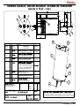
DICHIARAZIONE DI CONFORMITÀ CE ATTREZZATURA A PRESSIONE
EC DECLARATION OF CONFORMITY PRESSURE EQUIPMENT DECLARATION DE CONFORMITE MACHINE SOUS PRESSION
Caldaia1'#$)1",#4)e:
* Boiler in zona di applicazione articolo 3, comma 3 97/23/CE
* Chauffe-eau en zone d’application article 3, alinéa 3 97/23/CE
* Boiler in application area, article 3, section 3 97/23/EC
Norme applicate: Raccolte M,S, VSR edizione '78 e '95 conservate presso la sede legale.
Applied regulations: Collections M,S, VSR editions '78 and '95 and available in the registered office.
Normes appliquées: Recalte M, S, VSR edition '78 et '95 gardées chez la siège legale.
Disegno n° *"' *##+
Amministratore delegato *"$ "*#$"$%",,%,Ottavi Nando
ATTENZIONE: La presente dichiarazione va conservata e deve accompagnare sempre l'attrezzatura. Ogni uso dell'attrezzatura diverso da quello previsto dal
progetto é vietato. L'integrità e l'efficienza dell'attrezzatura e degli accessori di sicurezza sono a cura dell'utente. La presente dichiarazione perde la sua validità nel
caso in cui l’apparecchio venga modificato senza espressa autorizzazione del costruttore oppure se installato o utilizzato in modo non conforme a quanto indicato
nel manuale d’uso e nelle istruzioni.
ATTENTION: This declaration is to be kept with the equipment at all times and must always go together with the equipment. Any use of the equipment than for
the purposes for which it was designed is prohibited. The integrity and efficiency of the equipment of the safety devices are the responsibility of the user. The
declaration is null and void if the machine is modified without the express authorization of the manufacturer or if improperly installed and used in such a way that
does not comply with indications in the user’s manual and the instructions.
ATTENTION: Cette déclaration doit être conservée et doit toujours aller avec la machine. Toute utilisation de la machine différente de celle qui este prévue par le
projet est interdite. L'intégrité et l'efficacité de la machine et des accessoires de sécurité sont à la charge de l'utilisateur. La présente déclaration perd toute validité
dans le cas où l'appareil est modifié sans l'autorisation du constructeur ou si l'appareil est installé ou utilisé de façon non conforme à ce qui est indiqué dans le
manuel et dans le mode d'emploi.
Congratulations,
you have made an excellent choice.
By purchasing the
The purchase of a professional espresso coffee-maker involves various elements of selection: the name of the manufacturing firm, the machine’s
specific functions, its technical reliability, the option of immediate and suitable servicing, its price. You certainly evaluated all these factors and then
.
made your choice: the
We think you have made the best choice and after every coffee and cappuccino you will be able to assess this.
You will see how practical, convenient and efficient working with con
.
If this is the first time you have bought a Nuova Simonelli coffee machine, welcome to high quality coffee-making; if you are already a customer of ours,
we feel flattered by the trust you have shown us.
ENGLISH
Thanks of the preference.
With best wishes,
Nuova Simonelli S.p.A.
37
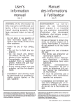
TECHNICAL CHARACTERISTICS
ENGLISH
H
D
B
C
A
Digit Version
2 Groups
NET WEIGHT
74 kg
GROS WEIGHT
POWER
DIMENSIONS
164 lb
88 kg
194 lb
102 kg
225 lb
80 kg
176 lb
100 kg
220 lb
115 kg
254 lb
4500 W
5000 W
5000 W
5000 W
5000 W
A
815 mm
A
32 1\16”
A
1045 mm
A
41 1\8”
A
1275 mm
A
50 3\16”
B
720 mm
B
28 5/16”
B
950 mm
B
37 3/8”
B
1180 mm
B
46 7\16”
C
565 mm
C
22 3\16”
C
565 mm
C
22 3\16”
C
565 mm
C
22 3\16”
D
370 mm
D
14 9\16”
D
370 mm
D
14 9\16”
D
370 mm
D
14 9\16”
H
565 mm
H
22 3/16”
H
565 mm
H
22 3/16”
H
565 mm
H
22 3/16”
2 Groups
3 Groups
NET WEIGHT
76 kg
168 lb
90 kg
198 lb
GROS WEIGHT
82 kg
181 lb
102 kg
225 lb
7300 W
7300 W
9100 W
9100 W
POWER
DIMENSIONS
4 Groups
4500 W
T3 Version
A
815 mm
A
32 1\16”
A
B
720 mm
B
C
565 mm
D
H
38
3 Groups
1045 mm
A
41 1\8”
28 5/16”
B
950 mm
B
37 3/8”
C
22 3\16”
C
565 mm
C
22 3\16”
370 mm
D
14 9\16”
D
370 mm
D
14 9\16”
565 mm
H
22 3/16”
H
565 mm
H
22 3/16”
INDEX
TECHNICAL CHARACTERISTICS . . . . . . .38
. . . . . . . . . .41
1.
DESCRIPTION
1.1
1.2
CONTROL PANEL DESCRIPTION . . . . . . . . . . . . . . 42
ACCESSORIES LIST. . . . . . . . . . . . . . . . . . . . . . . . . 43
2.
SAFETY PRESCRIPTION . . . . . . . . . . . . . .44
TRANSPORT AND HANDLING . . . . . . . . . .47
3.1
3.2
3.3
MACHINE IDENTIFICATION . . . . . . . . . . . . . . . . . . . 47
TRANSPORT . . . . . . . . . . . . . . . . . . . . . . . . . . . . . . . 47
HANDLING . . . . . . . . . . . . . . . . . . . . . . . . . . . . . . . . . 47
4.
INSTALLATION AND
PRELIMINARY OPERATIONS . . . . . . . . . . .47
4.1
4.2
WATER SPECIFICATIONS . . . . . . . . . . . . . . . . . . . . 48
ELECTRICITY SPECIFICATIONS . . . . . . . . . . . . . . . 48
5.
ADJUSTMENTS TO BE MADE
BY A QUALIFIED TECHNICIAN ONLY . . . .49
5.1
5.3
ADJUSTMENTS TO BE MADE
BY A QUALIFIED TECHNICIAN ONLY . . . . . . . . . . . 49
PRESSURE SWITCH (version S and V) / PUMP
(version S, V, Digit and T3) ADJUSTMENT. . . . . . . 49
HOT WATER ECONOMISER ADJUSTMENT . . . . . . 49
6.
USE . . . . . . . . . . . . . . . . . . . . . . . . . . . . . . . .50
6.1
COMMISSIONING PROCEDURE OR
AFTER BOILER MAINTENANCE (T3 VERSION). . .
TURNING THE MACHINE ON. . . . . . . . . . . . . . . . . .
MAKING COFFEE . . . . . . . . . . . . . . . . . . . . . . . . . . .
USING STEAM (Manual steam wand) . . . . . . . . . . .
MAKING CAPPUCCINO . . . . . . . . . . . . . . . . . . . . . .
HOT WATER SELECTION. . . . . . . . . . . . . . . . . . . . .
AUTOSTEAM (optional) . . . . . . . . . . . . . . . . . . . . . .
5.2
6.2
6.3
6.4
6.5
6.6
6.7
50
50
51
52
52
52
52
7.1
7.2
7.2.1
7.2.2
7.2.3
7.2.4
7.2.5
7.2.6
7.2.7
7.2.8
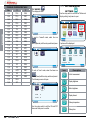
AURELIA T3 and DIGIT PROGRAMMING . .53
KEY. . . . . . . . . . . . . . . . . . . . . . . . . . . . . . . . . . . . . . .
PROGRAMMING (user mode) . . . . . . . . . . . . . . . . .
LANGUAGE . . . . . . . . . . . . . . . . . . . . . . . . . . . . . . . .
DOSE PROGRAMMING. . . . . . . . . . . . . . . . . . . . . . .
SET POINT TEMPERATURE. . . . . . . . . . . . . . . . . . .
KEY AND DISPLAY SETTINGS. . . . . . . . . . . . . . . . .
ENERGY SAVING . . . . . . . . . . . . . . . . . . . . . . . . . . .
DELIVERY COUNT . . . . . . . . . . . . . . . . . . . . . . . . . .
ALARMS. . . . . . . . . . . . . . . . . . . . . . . . . . . . . . . . . . .
TECHNICAL SETTINGS . . . . . . . . . . . . . . . . . . . . . .
53
53
54
54
56
58
60
62
63
64
8.
CLEANING . . . . . . . . . . . . . . . . . . . . . . . . . .66
8.1
8.2
8.3
8.4
SWITCHING OFF THE MACHINE . . . . . . . . . . . . . .
CLEANING THE OUTSIDE OF THE MACHINE . . . . .
CLEANING THE STAINLESS COFFEE-HOLDERS . .
CLEANING THE UNIT WITH
THE AID OF THE BLIND FILTER . . . . . . . . . . . . . . .
CLEANING FILTERS AND FILTER-HOLDERS. . . . . .
8.5
ENGLISH
3.
7.
66
66
66
66
66
9.
MAINTENANCE . . . . . . . . . . . . . . . . . . . . . .67
9.1
RESIN AND SOFTENER REGENERATION . . . . . . . 67
AURELIA II DIGIT T3 V ELECTRIC SYSTEM . . . .101
AURELIA II DIGIT T3 S ELECTRIC SYSTEM . . . .102
AURELIA II DIGIT V ELECTRIC SYSTEM . . . . . . .103
AURELIA II DIGIT BOILER DIAGRAM. . . . . . . . . .104
AURELIA II T3 (3 groups) BOILER DIAGRAM . . .105
AURELIA II T3 (2 groups) BOILER DIAGRAM . . .106
AURELIA II T3 (2-3 groups) BOILER DIAGRAM . .107
39
40
ENGLISH
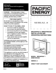
1.
DESCRIPTION
2
1
3
4
17
5
15
ENGLISH
6
16
7
14
13
12
11
10
9
8
Fig. 1
KEY
1 Steam knob
2 Hot water / steam delivery button
3 Control panel
4 Coffee delivery buttons
5 Steam knob
6 Filter-holder
7 Manual steam nozzle
8 Delivery unit
9
10
11
12
13
14
15
16
Main switch
2 coffees spout
Water level inside boiler
Pressure Gauge
Adjustable foot
Manual steam nozzle
Data plate
Hot water nozzle
17 Electric cup warmer (optional)
41
1.1
CONTROL PANEL DESCRIPTION
1
3
4
ENGLISH
2
Sunday
°C
°C
°C
1.2 bar
11
10
9
8
5
21 March 14:45
°C
3
Menu
7
6
Fig. 2
KEY
1 Machine On/Off light
2 Machine On/Off button
3 TFT display
4 Aurelia II Logo
5 USB port
6 Logo (T3 version)
7 Rotary switch
42
8
9
10
11
Cup warmer On/Off button
Cup warmer On/Off button
Wash light
Cup warmer On/Off light
1.2
ACCESSORIES LIST
A11
A03
A02
A06
A01
A07
ENGLISH
A05
A08
A04
A09
A10
CODE
Fig. 3
DESCRIPTION
2 GROUPS
3 GROUPS
4 GROUPS
(Digit only)
A01
Filling tube 3/8
1
1
1
A02
Unit tub draining tube
Ø 20 mm - l. 150 cm
1
1
1
A03
Worktop draining
tube Ø 25 mm l. 150 cm
1
1
1
A04
Filter-holder
3
4
5
A05
Double filte
2
3
4
A06
Single filter
1
1
1
A07
Blind filter
1
1
1
A08
Spring
3
4
5
A09
Double delivery spout
2
3
4
A10
Single delivery spout
1
1
1
A11
Coffee presser
1
1
1
43
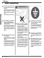
2.
SAFETY PRESCRIPTION
book is an integral and essential
☞ This
part of the product and must be given
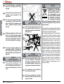
DANGER OF POLLUTION
ENGLISH
to the user.
Read this book carefully. It provides
important information concerning
safety of installation, use and maintenance.
Save it carefully for future reference.
Fig. 5
illustrations in this manual are
☞ The
purely for information purposes.
Your machine may differ slightly from
the one shown here.
Nuova Simonelli reserves the right to
make any changes to products and
the manual without the need for any
updates to previous products and
manuals.
unpacking, make sure the appli☞ After
ance is complete.
In case of doubts, do not use the
appliance, but consult a qualified
technician.
Packaging items which are potentially dangerous (plastic bags, polystyrene foam, nails, etc.) must be kept
out of children’s reach and must not
be disposed of in the environment.
44
Fig. 4
connecting the appliance
☞ Before
make sure the rating plate data cor-
respond with the mains.
This plate is on the front panel at the
top right hand side of the appliance.
The appliance must be installed by
qualified technicians in accordance
with current standards and manufacturer’s instructions.
The manufacturer is not liable for any
damage caused due to failure to
ground the system.
For the electrical safety of the appliance, it is necessary to equip the
system with the proper grounding.
This must be carried out by a qualified electrician who must ensure that
the electric power of the system is
sufficient to absorb the maximum
power input stated on the plate.
In particular you must ensure that the
☞ size
of the wiring cables is sufficient
to absorb power input.
The use of adapters, multiple sockets
or extensions is strictly forbidden. If
they prove necessary, call a fully
qualified electrician.
appliances powered at 220-230 V,
☞ For
the maximum impedance from the
mains must be no higher than 0.37
Ohm.
installing the device, it is nec☞ When
essary to use the parts and materials
supplied with the device itself.
Should it be necessary to use other
parts, the installation engineer needs
to check their suitability for use in
contact with water for human consumption.
machine must be installed in
☞ The
compliance with the local health
standards in force for plumbing systems.
Therefore, contact an authorized
plumber.
device needs to be supplied with
☞ The
water that is suitable for human con-
appliance is not suitable for use
☞ This
by children or persons with reduced
☞
physical, sensory or mental capabilities, or by persons with a lack of
experience or knowledge, unless
supervised or given instructions.
The maximum and minimum storage
temperatures must fall within a range
of [-5, +50]°C.
operating temperature must be
☞ The
within the range of [+5, +35]°C.
the end of installation, the device is
☞ Atswitched
on and taken to rated operat-
ing conditions, leaving it in a state in
which it is “ready for operation”.
The device is then switched off and
the whole hydraulic circuit is bled of
the first lot of water in order to
remove any initial impurities.
installation, the mains power
☞ During
system needs to be equipped with a
disconnector switch to cut off each
phase.
carrying out any maintenance
☞ Before
operation, the authorised service
engineer will switch off the machine
and open the disconnector.
all cleaning operations comply
☞ For
exclusively with the instructions
given in this booklet.
rules must be observed when
☞ Basic
using any electric appliance.
In particular:
do not touch the appliance when
hands or feet are wet;
do not use the appliance when
barefoot;
do not use the appliance when
barefoot;
CAUTION
RISK OF ELECTRIC SHOCK
do not pull the supply cord out of
the socket to disconnect it from
the mains;
do not leave the appliance
exposed to atmospheric agents
(rain, sun, etc.);
do not let the appliance be used
by children, unauthorised staff or
staff who have not read and fully
understood the contents of this
handbook.
Fig. 6
breaks down or fails
☞ Iftotheworkappliance
properly, switch it off. Any
intervention is strictly forbidden.
Repairs should only be made by the
manufacturer or authorized vice centres.
Only original spare parts must be
used.
Failure to observe the above, could
make the appliance unsafe.
installation, the qualified electri☞ For
cian must fit an omnipolar switch in
accordance with the safety regulations in force and with 3 (0,12) or
more mm (in) between contacts.
45
ENGLISH
☞
sumption and compliant with the
regulations in force in the place of
installation. The installation engineer
needs confirmation from the owner/
manager of the system that the water
complies with the requirements and
standards stated above.
This appliance must only be used as
described in this handbook. The
manufacturer shall not be liable for
any damage caused due to improper,
incorrect and unreasonable use.
The device is then refilled and taken
to rated operating conditions.
After reaching the “ready for operation”
condition, the following dispensing
operations are carried out:
- 100% of the coffee circuit through the
coffee dispenser (for more than one
dispenser, this is divided equally);
- 100% of the hot water circuit through
the water dispenser (for more than one
dispenser, this is divided equally);
- opening of each steam outlet for 1
minute;
At the end of installation, it is good
practice to draw up a report of the
operations.
dangerous overheating,
☞ Tomakeavoid
sure the supply cord is fully
CAUTION
uncoiled.
not obstruct the extraction and/or
☞ Dodissipator
grids, especially of the
cup warmer.
ENGLISH
☞
The user must not replace the appliance supply cord. If the cord is damaged, switch off the appliance and
have a qualified technician change
the cord.
appliances with current
☞ Single-phase
above 15 A and three-phase appli-
Fig. 7
CAUTION
RISK OF POLLUTION
the steam nozzle with care and
☞ Use
never place hands below the jet of
steam. Do not touch the nozzle immediately after us.
ances sold without plugs are directly
wired to the mains power and therefore, it is not possible to use a plug.
no longer using the appliance, we
☞ Ifrecommend
making it inoperative;
after removing the plug from the
mains electricity, cut the power supply cable.
CAUTION
RISK OF POLLUTION
not dispose of the machine in the
☞ Doenvironment;
for the disposal, contact an authorized service center or
contact the manufacturer for indications.
Fig. 8
CAUTION
RISK OF INTOXICATION
remind you that before carrying
☞ We
out any installation, maintenance,
unloading or adjustment operations,
the qualified operator must put on
work gloves and protective footwear.
maximum noise disturbance
☞ The
level is lower than 70db.
the pipe connecting to the mains
☞ Ifwater
is replaced the old pipe must
never be re-used.
46
INFORMATION TO THE USERS
Under the senses of art. 13 of
Law Decree 25th July 2005, n.
151 “Implementation of the
Directives/ Guidelines 2002/95/
CE, 2002/96/CE and 2003/108/
CE, concerning the reduction
of the use of dangerous substances in electric
and electronic equipment, as well as the disposal of wastes“.
The symbol of the crossed large rubbish container
that is present on the machine points out that the
product at the end of its life cycle must
Be collected separately from the other wastes.
The user for this reason will have to give the
equipment that got to its life cycle to the suitable
separate waste collection centres of electronic
and electrotechnical wastes, or to give it back to
the seller or dealer when buying a new equipment
of equivalent type, in terms of one to one. The
suitable separate waste collection for the following
sending of the disused equipment to recycling, the
dealing or handling and compatible environment
disposal contributes to avoid possible negative
effects on the environment and on the people's
health and helps the recycling of the materials the
machine is composed of. The user's illegal disposal of the product implies the application of
administrative fines as stated in Law Decree
n.22/1997” (article 50 and followings of the Law
Decree n.22/1997).
3.
TRANSPORT AND HANDLING
3.1
MACHINE
IDENTIFICATION
Always quote the machine serial number in all
communications to the manufacturer, Nuova
Simonelli.
3.2
TRANSPORT
The machine is transported on pallets which
also contain other machines - all boxed and
secured to the pallet with supports.
Before carrying out any transport or handling
operation, the operator must:
SXWRQZRUNJORYHVDQGSURWHFWLYHIRRWZHDU
as well as a set of overalls which must be
elasticated at the wrists and ankles.
The pallet must be transported using a suitable means for lifting (e.g., forklift).
HANDLING
CAUTION
RISK OF IMPACT
OR CRASHING
During all handling operations, the operator
must ensure that there are no persons,
objects or property in the handling area.
The pallet must be slowly raised to a height
of 30 cm (11,8 in) and moved to the loading
area. After first ensuring that there are no
persons, objects or property, loading operations can be carried out.
Upon arrival at the destination and after
ensuring that there are no persons, objects
or property in the unloading area, the proper lifting equipment (e.g. forklift) should be
used to lower the pallet to the ground and
then to move it (at approx. 30 cm (11,8 in)
from ground level), to the storage area.
INSTALLATION
AND
PRELIMINARY
OPERATIONS
After unpacking, assess that the machine and
its accessories unit are complete, then proceed
as follows:
SODFHWKHPDFKLQHVRWKDWLWLVOHYHORQDIODW
surface;
DVVHPEOHLWVVXSSRUWLQJIHHWE\LQVHUWLQJWKH
insert into the cylindrical unit;
WZLVW WKH UXEEHU IRRW LQWR WKH VFUHZ WKUHDG
inside the unit;
VFUHZ WKH ZKROH DVVHPEOHG XQLW LQWR WKH
allotted setting for the machine’s adjustable
feet;
OHYHOWKHPDFKLQHE\UHJXODWLQJWKHDGMXVWDble feet;
NOTE: the unit grooves have to face upwards,
as shown in the following illustration.
CAUTION
RISK OF IMPACT
OR CRASHING
Before carrying out the following operation,
the load must be checked to ensure that it is
in the correct position and that, when the
supports are cut, it will not fall.
The operator, who must first put on work
gloves and protective footwear, will proceed
to cut the supports and to storing the product. To carry out this operation, the technical characteristics of the product must be
consulted in order to know the weight of the
machine and to store it accordingly.
Fig. 10
It is advisable to install a softener (1) and then
a mesh filter (2) on the external part of the
plumbing system, during preliminaries and after
levelling the machine.
47
ENGLISH
Fig. 9
3.3
4.
In this way impurities like sand, particles of
calcium, rust etc will not damage the delicate
graphite surfaces and durability will be guaranteed.
Following these operations, connect the plumbing systems as illustrated in the following figure.
4.2
ENGLISH
WARNING
Avoid throttling in the connecting tubes.
Assess that the drain pipe (3) is able to
eliminate waste.
2
3
1
Fig. 11
KEY
1 Softene
2 Mesh filter
3 Drain Ø 50 mm
4.1
IRUV 230 / monophase voltage
ELECTRICITY
SPECIFICATIONS
CAUTION
RISK OF SHORT CIRCUITS
Fig. 13
KEY
1 Black
2 Grey
3 Brown
4 Blue
5 Yellow-green
The machine must always be protected by
an automatic omnipolar switch of suitable
power with contact openings of equal distance or more than 3mm.
Nuova Simonelli is not liable for any damage to people or objects due to not observing current security measures.
NOTE: At the start of the day’s activities and in
any case, if there are any pauses of
more than 8 hours, then it is necessary
to change 100% of the water in the circuits, using the relevant dispensers.
Prior to connecting the machine to the electrical
mains, assess that the voltage shown on the
machine’s data plate corresponds with that of
the mains.
If it does not, carry out the connections on the
basis of the available electrical line, as follows:
NOTE: In case of use where service is continuous, make the above changes at least
once a week.
IRUV 380 / 3 phases voltage + Neutral:
WATE SPECIFICATIONS
Monitoring of water recipe to keep it within
required levels and maintenance of filtration
system is the user's responsibility.
Failing to meet and maintain water at the following levels will void the entire warranty:
WRWDOKDUGQHVVSSPSDUWVSHUPLOOLRQ
water line pressure between 2 – 4bar and
water to be cold
48
PLQIORZUDWHOKU
ILOWUDWLRQOHYHOEHORZPLFURQ
WGVWRWDOGLVVROYHGVROLGVOHYHOEHWZHHQ
– 250 ppm
alkalinity level between 10 – 150 ppm
FKORULQHOHYHOOHVVWKDQPJO
3KOHYHOEHWZHHQDQG
Fig. 12
5.
ADJUSTMENTS TO BE MADE BY A QUALIFIED TECHNICIAN ONLY
5.1
ADJUSTMENTS TO
BE MADE BY A
QUALIFIED
TECHNICIAN ONLY
To fill the boiler manually for the first time, proceed as follows
UHPRYHWKHZRUNWRSJULG
XVHWKHPDQXDOOHYHOFRFN³$´WRDOORZZDWHU
to enter the boiler;
RQFHWKHPD[LPXPOHYHOKDVEHHQUHDFKHG
as indicated by the optical level, turn tap “A”
off;
A
PRESSURE SWITCH
(version S and V) /
PUMP (version S, V,
Digit and T3)
ADJUSTMENT
NOTE: this operation can be carried out while
the machine is turned on.
are fitted with a hot
All models
water mixer, which serves to adjust the temperature of the water leaving the wand and to
optimise system performance.
To set the hot water economy device, use a
screwdriver on the screw in the top part of the
machine, as shown in the figure.
7XUQLW&/2&.:,6($17,&/2&.:,6(WR
REDUCE / INCREASE the temperature of
the hot water;
5.3
HOT WATER
ECONOMISER
ADJUSTMENT
The electronic control unit has a lithium battery
to power the clock; the battery has an autonomy of about three years, after which it will need
to be replaced.
In case of an extended period of machine stoppage, the clock can be stopped:
ZLWKWKHPDFKLQHRIIWKHGLVSOD\ZLOOUHDG
CLOCK DISABLED
®
OFF
KROGWKH212))NH\GRZQ
to release the clock.
MAX
for 5 sec.
WARNING
Fig. 15
MIN
Fig. 14
VZLWFKWKHPDFKLQHRQE\SODFLQJWKHJHQeral switch on “I”; this will activate the level
gauge which will automatically maintain the
water level inside the boiler.
Replacement of the lithium battery must be
carried out EXCLUSIVELY by Qualified
Technician.
Nuova Simonelli cannot be held liable for
any damage to people or things due to non
observance of the safety prescriptions
described in this booklet.
49
ENGLISH
NOTE: this operation must be carried out with
the machine turned off.
are equipped with a
All models
level gauge to keep the water level inside the
boiler constant. When using the machine for
the first time, it is advisable to fill the boiler by
hand to avoid damaging the electrical resistor
and turning on the electronic protection.
If this should happen, just turn the machine off
and then start it up again to complete its loading procedure (see “MACHINE OPERATION
MESSAGES”).
5.2
6.
USE
Before starting to use the appliance, the operator
must be sure to have read and understood the
safety prescriptions contained in this booklet.
6.2
SWITCH ON:
ENGLISH
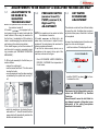
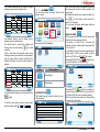
6.1
COMMISSIONING
PROCEDURE OR
AFTER BOILER
MAINTENANCE
(T3 VERSION)
When commissioning the machine for the first
time or after carrying maintenance switch ON
the machine using the main switch positioned
lower down and on the right and proceed as
follows:
,I WKH PHVVDJH ³2)) ± &/2&.
DISENABLED” appears on the display proceed as follows in step three.
2) If the display reads “OFF“ press the ON/
7KHGLVSOD\ZKLFKLVQRWLOOXPLQDWHGZLOOUHDG
TURNING THE
MACHINE ON
plug the machine into the
power socket and press the
switch “A” so it is in position “I”;
the machine will switch on.
Pressing the switches “B” and
"C" in the “I” position will switch
on the LEDs, independently of
the position of switch "A".
OFF
NOTE: The machine is not operational, since
the main switch only powers the electronic card.
WARNING
B
C
A
Fig. 16
For electronic card maintenance, turn the
machine off by means of the external main
switch or disconnect the plug.
MANUAL SWITCHING ON/OFF
WARNING
OFF
NH\XQWLOLWUHDGV³2))±&/2&.
DISABLED“ and then proceed as described
in step 3.
3) Switch on the machine using the ON/OFF
If the self-diagnostics report anomalies or
failures, the operator MUST NOT intervene.
Please contact the Assistance Centre.
key and automatically after the
machine has switched on, some water will
be poured from the groups for about 45
seconds to make sure that the coffee boiler
tanks have been properly filled.
This cycle cannot and must not be interrupted.
If this cycle is interrupted due to a power
outage or if the machine is accidentally
switched off from the main switch, the next
time the machine is switched on, the cycle
will be started again for approximately 45
seconds more.
The lit display will show the firmware version
for about 1 second:
50
®
Automatic On/Off NOT PROGRAMMED
NOTE: make sure that the general switch is
always on the position “I”.
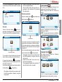
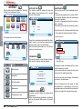
SWITCH ON:
®
Release firmware 0.37.1
press the On/Off button
for about 2 seconds until the
light switches on and the buzzer makes a beep sound.
The control unit will start up an
auto diagnosis cycle to check
the functions, all the selection
keys will light up.
After the diagnostics stage, the
"Home Page" will open on the
screen:
Sunday
°C
°C
6.3
Automatic On/Off PROGRAMMED
NOTE: make sure that the general switch is
always on the position "I".
21 March 14:45
°C
Menu
NOTE: on completion of the check up all the
selection keys are activated.
Unhitch the filter-holder and fill it with one or
two doses of ground coffee depending on the
filter used.
Fig. 17
Sunday
WARNING
°C
°C
21 March 14:45
°C
In case the auto diagnosis indicates error or
malfunction, call an assistance centre; the
operator MUST NOT intervene.
0.05 bar
SWITCHING OFF: press the ON/OFF button
for about 2 seconds, until the
light switches off.
The machine will switch off and
the display will read:
Menu
NOTE: once the auto diagnosis has been completed all the keys are activated.
WARNING
If the self-diagnostics report anomalies or
failures, the operator MUST NOT intervene.
Please contact the Assistance Centre.
®
OFF
Press the coffee with the provided coffee
presser, dust off any coffee residue from the rim
of the filter (this way the rubber gasket will last
longer).
Insert the filter in its unit.
Press the desired coffee button.
NOTE: when in pause, leave the filter-holder
inserted in the unit so that it will keep
warm.
To guarantee the utmost thermic stability during use, the delivery units are
thermo-compensated with complete hot
water circulation.
The machine will SWITCH ON at the first
programmed switch-on time (see the
PROGRAMMING chapter and the ENERGY
SAVING section).
NOTE: the machine can be switched on or off
manually as indicated in the previous
paragraphe.
51
ENGLISH
0.05 bar
The machine will SWITCH OFF at the first
time set for stopping the coffee maker (see
the PROGRAMMING chapter and the
ENERGY SAVING section).
The control unit will perform an auto diagnosis
of all functions and all of the selection keys will
light up.
After the diagnostics stage, the "Home Page"
will open on the screen:
MAKING COFFEE
6.4
USING STEAM
(Manual steam
wand)
6.5
CAUTION
RISK OF BURNS OR SCALDING
ENGLISH
While using the steam nozzle, you must pay
attention to not place your hands beneath it
or touch just after it has been used.
To use the steam function, pull or push the relevant lever, as shown in the figure.
By pulling it completely the lever will hold a
position of maximum delivery; by pushing it, the
lever will automatically give way.
The two steam nozzles are articulated to guarantee their easy use.
MAKING
CAPPUCCINO
To obtain the typical cappuccino foam, immerse
the nozzle all the way into a container 1/3 full of
milk (preferably cone-shaped). Turn on the
steam. Before the milk starts to boil, pull the
nozzle slightly up and lightly move it vertically
across the surface of the milk. When you have
completed the procedure, clean the nozzle
carefully with a soft cloth.
The hot water wand will deliver water for the
amount of time equivalent to the set value (see
PROGRAMMING section and the DOSE
PROGRAMMING section) or press the button
again to stop pouring.
NOTE: Hot water can be delivered at the same
time as coffee.
6.7
AUTOSTEAM
(optional)
CAUTION
RISK OF BURNS OR SCALDING
Fig. 19
6.6
HOT WATER
SELECTION
When using autosteam, take great care not
to place your hands underneath it and never
touch it immediately afterwards.
This serves to deliver steam and the temperature is controlled by a probe. The temperature is
set during the programming stage.
To enable autosteam, press the steam button
Fig. 18
NOTE: Before using the steam wand, always
bleed out any condensation for at least
2 seconds or according to the manufacturer’s instructions.
CAUTION
RISK OF BURNS OR SCALDING
While using the hot water nozzle, pay careful attention not to place your hands beneath
it or touch it just after it has been used.
This nozzle delivers hot water to make tea or
herb teas.
Place a suitable container under the hot water
nozzle. Press the hot water select button once;
the light
52
will switch on.
; the light will switch on.
The steam delivery will stop as soon as the set
temperature for the liquid is reached.
NOTE: Steam can be delivered at the same
time as coffee.
7.
AURELIA T3
and DIGIT
PROGRAMMING
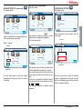
7.1
7.2
2
Sunday
°C
°C
Icon
Switch on the machine as described in the
“Use” chapter – the “Switching the machine On/
Off” section. The display shows the "Home
Page".
KEY
1
PROGRAMMING
(user mode)
3
Group temperatures
(T3 version only, if enabled
during programming)
21 March 14:45
°C
Description
Language.
Dose programming.
Setpoint temperature and
group/boiler offset.
ENGLISH
Key and display settings.
Sunday 21 March 14:45
1.2 bar
Menu
°C
5
4
Nr.
°C
°C
1
Domenica 21 Marzo 14:45
5
Energy saving.
Fig. 20
Interactive programming /
viewing area.
DATE and TIME
ROTARY SWITCH:
Turn to move through the
interface.When the icon is
selected, it changes colour
and lights up white; press
to enable the selected
function/icon.
Programming also makes it
possible to increased and/
or reduce settings.
3
4
°C
Description
°C
2
°C
Menu
MENU ICON
To open the main menu
and return back a level during navigation.
Home
HOME ICON:
To return to the "Home
Page" while navigating
through the interface.
Delivery counts.
1.2 bar
Menu
Current boiler
Delivery times
pressure
(if enabled during programming)
Alarms.
Technical settings.
Menu
Select
and press the rotary switch to
access the main menu.
Main Menu
Language
Dose
programming
Energy
saving
Pour
count
Temperature
ure Key
u
ey and displa
display
disp
setpointt
settings
Alarms
Technical
settings
53
3 options will be displayed:
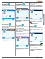
7.2.1 LANGUAGE
Use the rotary switch to move to the "Language"
icon. Press the icon to open:
Main Menu
Language
Dose
programming
Energy
saving
Pour
count
All programmable keys will start to flash:
Dose prog
programming
Dose
Dose
programming transferr
Standard
doses
Temperature
ure Key
u
ey and displa
disp
display
setpointt
settings
ENGLISH
Fig. 21
Alarms
Technical
settings
Icon
Description
Programming single doses.
This shows the page for selecting the language
for the whole interface.
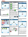
Coffee:
Press the button to be programmed; the display
will show the icon for the selected button and
the setting already programmed.
Dose transfer between groups.
Dose programming
Language
L
Standard dose setting.
Italian
English
h
Franch
German
G
Use the rotary switch to select one of the three
options and then press to access.
Spanish
Use the rotary switch to move within the screen
and press to confirm the language selection.
7.2.2
DOSE PROGRAMMING
DOSE PROGRAMMING
The display will show:
:
Dose
programming
Select dose
Main Menu
Language
Energy
saving
54
Pour
count
Alarms
Key
ey and displa
disp
display
settings
Technical
settings
Programmed volume
Dose programming
Use the rotary switch to move to the "Dose
Program." icon and press to open:
Dose
Temperature
mperature
re
programming setpoint
Volume CC
Select the icon
switch and press.
again with the rotary
It is possible to change the dose using the rotary
switch and then pressing it to confirm the setting.
Or, press the coffee key to programme, the delivery
will start and in the meantime, all of the other lights
will switch off.
Once the required dose has been poured, press the
to stop delivery.
continuous coffee button
7KH GLVSOD\ ZLOO VKRZ WKH QHZ YDOXH DQG LW
will still be possible to change it using the
rotary switch.
3UHVVWKHURWDU\VZLWFKLQDQ\FDVHWRFRQfirm the programmed dose.
7KHFRIIHHEXWWRQWKDWKDVEHHQSURJUDPPHG
is then switched off by pressing the rotary
switch.
To continue programming the different keys,
select the icon with the rotary switch and press
on it.
Dose programming
3UHVVWKHURWDU\VZLWFKLQDQ\FDVHWRFRQfirm the programmed dose.
7KH KRW ZDWHU EXWWRQ WKDW KDV EHHQ SURgrammed is then switched off by pressing
the rotary switch.
Autosteam (optional):
Dose
programming
Select dose
Transfert doses
and make sure
Press the steam button
that the button
DOSE TRANSFER
:
This function serves to transfer the value of the
programmed dose settings to other groups.
Select the group to be used as a “source” and
confirm:
lights up:
3
Source
Dose programming
to be proPress the hot water button
grammed; the display will show the icon for the
chosen function and the programmed setting.
Temperature °C
S
Select
the “destination” group for the copy of the
settings and confirm
NOTE: The group used as a source is uninhibited.
Transfert doses
Dose programming
Set temperature
Volume CC
Programmed volume
IT Is possible to change the dose using the rotary
switch and then pressing it to confirm the setting.
to programme,
Or, press the hot water key
the delivery will start and in the meantime, all of the
other lights will switch off.
Once the required dose has been poured, press the
hot water button
It is possible to change the temperature using the
rotary switch and the press to confirm the setting.
Or, press the steam key to programme, the delivery
will start and in the meantime, all of the other lights
will switch off.
Once the required temperature has been reached,
to stop delivery.
press the steam button
7KH GLVSOD\ ZLOO VKRZ WKH QHZ YDOXH DQG LW
will still be possible to change it using the
rotary switch.
3UHVVWKHURWDU\VZLWFKLQDQ\FDVHWRFRQfirm the set temperature.
The programmed steam button switches off
when the rotary button is pressed.
3
Source
3
Destination
STANDARD DOSES
:
This function serves to recall the “Standard
dose" settings for groups.
The display shows:
Standard doses
Select standard dose
3
to stop delivery.
7KH GLVSOD\ ZLOO VKRZ WKH QHZ YDOXH DQG LW
will still be possible to change it using the
rotary switch.
Select the coffee unit to apply the “standard dose"
settings and press the rotary switch to confirm.
55
ENGLISH
Hot water:
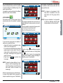
7.2.3
SET POINT
TEMPERATURE
Use the rotary switch to move to the "Set point
temperature" and press to enter:
GROUP SETPOINT (T3 version only)
The display will show:
:
GROUP OFFSET ADJUSTMENT:
From the screen:
Group setpoint
Group setpoint
M
Main Menu
3
3
Group setpoint
Language
Dose
programm
ming
programming
Temperature
ture Key
y and dis
disp
display
setpoin
ntt
n
setpoint
settings
Group setpoint
94.0
94.0
93.8
93.8
ENGLISH
Group temperature
Energy
saving
Pour
count
s
Alarms
Technical
settings
Setpoint
Boiler
Boiler
se
etpointt
setpoint
Steam
Ste
eam boiler
bo
oiler
settpoint
setpoint
92.8
Cup
Cup warmer
93.8
92.0
92.8
92.8
92.8
Use the rotary switch to select the coffee group
to adjust and confirm by pressing.
4 options will be displayed:
Group
setpointt
92.0
93.8
Group temperature
Group 1 example:
Hold down the washing key
to access
offset and group temperature adjustment.
The next screen will be:
Setting programmed
/ to be programmed
3
Group offset
Group setpoint
3
1.0
1.0
1.0
Group setpoint
Icon
Description
94
94.0
0
93.8
93.8
Group temperature
Group setpoint
(T3 version only).
Setpoint caldaie
(solo versione T3).
Steam boiler setpoint.
Cup warmer.
56
110.8
109.6
109.6
Instant setting
Turn the rotary switch to select the required
temperature for the group, then press to confirm.
With the rotary switch it is possible to select the
group offset to be adjusted and press to proceed.
Use the rotary switch to adjust the value of the
group offset and then confirm with by pressing
the switch.
At this point, it is possible to adjust the offset of
the other groups with the same procedure or to
select Menu or Home .
This setting is reserved to qualified service
engineers.
BOILER SETPOINT (T3 version only):
The display shows:
BOILER OFFSET ADJUSTMENT:
From the screen:
STEAM BOILER SETPOINT
The display shows:
Boiler setpoint
:
Steam boiler setpoint
3
Boiler setpoint
3
Boiler setpoint
93 4
93.4
93 4
93.4
Steam boiler setpo
setpoint
93.4
1 17
1.17
Boiler setpoint
93
4
93.4
93
4
93.4
Boiler temperature
93.4
Max
Max
Steam boiler setpoint
Max
0.86
Boiler temperature
Max
Max
Max
Hold down the washing key
to access
offset and boiler temperature adjustment.
The next screen will be:
Select the steam icon and confirm with the
rotary switch.
Set value
Boiler 1 example
Set value
Steam boiler setpoint
Group setpoint
3
Boiler Setpoint
3
Steam boiler setpo
setpoint
Group setpoint
94.0
Boiler setpoint
94
0
94.0
93.8
93.8
93.8
93.8
Group temperature
92.0
92.8
1.17
1
17
Steam boiler setpoint
0.86
92.8
Boiler temperature
110.8
109.6
109.6
Instant value
Instant value
Turn the rotary switch to select the required
temperature for the group; press it to confirm
the setting.
Use the rotary switch to select the coffee boiler
for offset adjustment and press it to proceed.
Also use the rotary switch to set the offset value
for the group and then press the switch to confirm.
At this point it is possible to adjust the offset of
other groups with the same procedure or select
Menu
or Home .
This setting is reserved to qualified service
engineers.
Turn the rotary switch to select the required
pressure / temperature for the boiler (see the
table on the following page) and then press the
switch to confirm the setting.
57
ENGLISH
Select the coffee boiler to be adjusted and confirm by pressing the rotary switch.
ENGLISH
PRESSURE-TEMPERATURE TABLE
Bar
°C
°F
0,50
110,5
230,9
0,55
111,5
232,7
0,60
112,5
234,5
0,65
113,5
236,3
0,70
114
237,2
0,75
115
239
0,80
115,5
239,9
0,85
116,5
241,7
0,90
117,5
243,5
0,95
118
244,4
1,00
119
246,2
1,05
119,5
247,1
1,10
120,5
248,9
1,15
121
249,8
1,20
122
251,6
1,25
122,5
252,5
1,30
123
253,4
1,35
124
255,2
1,40
124,5
256,1
1,45
125
257
1,50
126
258,8
1,55
126,5
1,60
127
7.2.4
CUP WARMER
:
The display will read:
Cup warmer
KEY AND DISPLAY
SETTINGS
Use the rotary switch to move to the "Button and
display setting” and press to open:
Main Menu
Manual
Manua
al
Timed
T
Language
To work in "manual" mode, select the icon
Manual
(Manual) with the rotary switch and press:
Energy
saving
Dose
Temperatur
Temperature
re
programming setpoint
Pour
count
Alarms
Key and display
settings
Technical
settings
6 options will be displayed:
Key
Ke
ey an
and
d displa
display settings
Cup warmer
Manuall
Timed
To work in “timer” mode, select the timer icon
Timed
(Timed) with the rotary switch and press it.
The following screen will open:
Cup warmer
Unit of
measure
Display
Diiisplay
brightness
brrrightne
ess
Pour
temperature
temperat
ture
Pour
Po
our
time
tim
me
Icon
Key
Key
brightness
brightnes
ss
Display
Display
timeout
tim
meout
Description
Unit of measurement
Display brightness
Button brightness
Manual
Timed
T
Time ON
20
Time OFF
40
Display timeout
Delivery temperature
Use the rotary switch to edit the ON and OFF
times and then press to confirm.
58
Delivery time
UNIT OF MEASURE
:
This screen serves to change the unit of measure for the temperature used to control the
whole interface:
:
BUTTON BRIGHTNESS
Use this function to set the brightness of the
keys:
DELIVERY TEMPERATURE
(T3 version only):
This function serves to activate/deactivate the
display for the group delivery temperature on
the "Home Page":
Key brightness
Pour temperature
Unit of measure
Unit of measure
9
DISPLAY BRIGHTNESS
:
This function serves to adjust the standard
brightness of the display:
Display brightness
10
Use the rotary switch to choose the level and
press it to confirm.
Use the rotary switch to select
/
and press to confirm.
:
DISPLAY TIME OUT
Use this function to set the display "Time-out"
time (low-brightness display).
Example. Set to 5 min, if the machine is not
used for more than 5 minutes, the display
brightness will be reduced.
The brightness will return to normal as soon
as the machine is used again.
:
DELIVERY TIME
This function serves to activate/deactivate the
display for the delivery time on the "Home
Page"
Pour time
Display timeout
Timed
Use the rotary switch to choose the level and
press it to confirm.
20 min.
Use the rotary switch to choose the time (minutes) and press to confirm.
If you decide to view the delivery time
,
use the rotary switch to select from the following
options:
7LPHUYDQLVKHVDIWHUVHF
3HUVLVWHQW UHPDLQV RQ WKH GLVSOD\ XQWLO WKH
next coffee).
59
ENGLISH
Use the rotary switch to select and press it to
confirm.
Pour time
Icon
Description
Programmable day example:
Weekly program
Weekly schedule.
Monday
Active groups.
Persistent
Times ON
ENGLISH
Standby active.
After selecting the option with the rotary switch,
confirm by pressing.
7.2.5 ENERGY SAVING
Use the rotary switch to select the "Energy saving" icon and press to open the function:
WEEKLY PROGRAMMING
:
This page serves to set the days off for the
machine and the days in which its automatic
switch on and off functions are programmed.
When the page is opened it will show the configuration of the first day of the week (Monday).
Turn the rotary switch to view the configuration
for the days until the last day of the week, after
Menu
Home
and
which select with the
icons.
The operation is cyclical.
Main Menu
Times OFF
00:00
Weekly program
00:00
OFF day example:
Weekly program
Sunday
To save changes, press the rotary switch. At this
point, the day is active, the hours will start to
flash for the ON time.
Monday
Language
Dose
prog
gramming
programming
Energy
saving
Pour
count
Weekly program
emperature
ure Key
u
y and display
disp
displ
Temperature
setpointt
settings
Times ON
Alarms
Technical
settings
00:00
Monday
Times OFF
00:00
Times ON
This shows 3 options:
Energy saving
Energ
Weekly
program
60
Active
A
groups
groups
Active
Active
Standby
Sttandby
To change the configuration for one day, this
day must be shown on the display and then the
rotary switch must be pressed.
At this point, an icon
/
will be
selected to signal if that day there is a programmed switch on or off time (
) or not
(
).
00:00
Times OFF
00:00
Turn the rotary switch to view and change the
setting.
Turn the rotary switch to view and change the
setting.
Press the rotary switch to store the setting and
pass on to change the minutes for the ON time.
The previous procedure is repeated with minutes and hours for the ON and OFF times.
Once the minutes have been saved for the OFF
time, the machine returns to the initial condition
where, by turning the rotary switch, it is possible
to view the settings for the different days of the
week, home and menu.
it is possible to view the settings for the different
days of the week, home and menu.
Active groups
Active
groups
°C
°C
21 March 14:45
°C
The change is not permanent in that every time
it is switched on from the main switch, all of the
groups will be active.
NOTE: The change is not permanent in that
every time it is switched on from the
main switch, all of the groups will be
active.
1.2 bar
Menu
The change is permanent and can only be cancelled following the same procedure as used to
enable it.
It is also possible to deactivate the groups without entering the programming mode.
From the following stand-by screen:
NOTE: If a group is disabled, it is not possible
to make any deliveries and the boiler
heating elements will be switched off.
Sunday 21 March 14:45
1
2
3
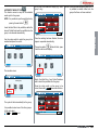
To set the active groups when the machine is
switched on, proceed as follows:
$FFHVV WKH IXQFWLRQ E\ SUHVVLQJ WKH URWDU\
switch on the active group icon.
,WLVSRVVLEOHWRDFWLYDWHGHDFWLYDWHLQGLYLGXDO
groups using the rotary switch. Press the
rotary switch to confirm and pass on to the
next group. Confirming the last group will
return to the menu.
3UHVV WKH LFRQ Home to go back to the
home page.
°C
°C
°C
1.2 bar
Menu
Press the button
and coffee key together
in case of the S version, or the long coffee
key
on the V version; the corresponding
group will be disabled, causing the display to
read (E.g. group 1 de-activated):
Sunday
NOTE: To make the change effective, it is necessary to quit the programming mode,
switch the machine on and off from the
main switch, which us located In the
bottom right.
When the deactivated group is switched back on,
its colour will be darker and the group will no
longer be operational (e.g. group 1 deactivation).
°C
°C
1.2 bar
21 March 14:45
°C
Menu
61
ENGLISH
ACTIVE GROUPS
:
This function serves to set the groups that are
actually active when the machine is switched
on:
Sunday
ENGLISH
ACTIVE STANDBY
:
This function allows the machine to enter standby mode or not, which makes it possible to
choose whether or not to switch off the machine
completely or to keep it at a set pressure (less
than working levels).
Use the rotary switch to select the following
options:
OFF: during the OFF state, the machine is
completely switched off and the display
reads "OFF"
Active standby
0.50 bar
ON 0.80 bar: during the OFF state, the
machine maintains a pressure of 0.80 bar
and the display (set to minimum brightness)
reads "LOW CONSUMPTION"
Main Menu
Language
ge
Dose
prog
gramming
programming
Energy
saving
Pour
count
Tem
emperature
ure Key
u
y and disp
Temperature
display
setpoint
s
setpoint
settings
Technical
settings
A
Alarms
A screen will open to view the counters:
Pour count
Active standby
Active standby
Pour count
0.80 bar
Select the delivery counter icon
press the rotary switch.
ON 0.10 bar: during the OFF state, the
machine maintains a pressure of 0.10 bar
and the display (set to minimum brightness)
reads "LOW CONSUMPTION".
Active standby
0.10 bar
ON 0.50 bar: during the OFF state, the
machine maintains a pressure of 0.50 bar
and the display (set to minimum brightness)
reads "LOW CONSUMPTION.
62
Press the rotary switch to confirm the required
option.
This operation is used with both manual switching
on/off using the button
, and automatic
switching on/off by programming the machine.
On the counter page, it is possible to view 2
tables that show the counters; to pass from one
to the other, use the rotary switch.
The first table shows the counts for the single
doses of each group:
If the on/off button
, is pressed during one of
the three active standby states (0.10 bar, 0.50
bar, 0.80 bar), the machine will switch off completely.
If the button is pressed again, this will switch on
the machine.
7.2.6 DELIVERY COUNT
Use the rotary switch to move to the "Delivery
count" icon and press to open:
and
3
Continue
5
0
0
0
0
0
0
0
0
0
0
0
1
0
0
The second table shows the total for groups,
washing, services and absolute total:
7.2.7 ALARMS
Use the rotary switch to select "Alarms" and
press to open:
3
Main Menu
Total grp
6
6
6
Washes
7
1
2
Total
18
4
Language
Dose
programming
programm
ming
Energy
saving
Pour
count
Temperature
Key
Temperatu
emperature
u
ure
y and display
disp
displ
setpoint
settings
setpoint
s
Turn the rotary switch to navigate through the
two pages with the list of errors stored in the
control unit.
To delete the alarm history, press the wash button
. on the control panel and hold it
down for 3 seconds.
To quit, press the rotary switch again and then
Menu or
Home .
select
1
. for a few
holding down the wash button
seconds.
Once in this mode, the table will contain a red
rectangle showing the value that can be deleted.
Use the rotary switch to select the field to be
deleted and press the rotary switch again to
delete it.
Technical
Te
echnical
settings
se
ettings
Two options will be displayed:
Alarms
Alarms
history
w
washing
a
llarm
allarm
WASH ALARMS:
This function serves to set the timer (hours and
minutes) for the group wash alarm.
E.g. setting 1 h and 30 min., will cause the
machine to send a wash alarm message after
1h and 30 min.
It is possible to access this function pressing the
rotary switch. Use the rotary switch to select
from the ACTIVE and NON ACTIVE modes.
Selecting NON ACTIVE
using the rotary switch will return to the main menu.
Icon
Description
3
Total grp
6
6
6
Washes
7
1
2
4
1
Alarm history
Wash alarms
Total
18
To quit the delete mode, press the wash button
again.
ALARM HISTORY
:
This function serves to view the history of control unit alarms:
To quit the count mode, press the rotary switch
Menu or
Home .
again and then select
Selecting ACTIVE
it is then necessary to
use the rotary switch to set the hours and minutes after which the alarm message appears.
After the minutes have been set, the machine
returns to the main menu.
Error found
Cup warmer probe 1 error
Pressure error
Group dose error 1
Group dose error 2
hh mm
Group dose error 1
03 30
63
ENGLISH
The different fields in the two tables can be
deleted using the delete mode.
The delete mode is entered by pressing and
Alarms
7.2.8
TECHNICAL
SETTINGS
Use the rotary switch to highlight the “Technical
settings” icon and press to open:
Main Menu
DATE AND TIME
:
This function serves to change the date and
time setting for the machine and it is viewed
from the "Home Page".
ENGLISH
Date and time
Language
Dose
programming
Energy
saving
Pour
count
emperatur
ure Key
y and display
disp
Temperature
setpoint
settings
setpoint
Alarms
Technical
settings
2013
March
8
Friday
14:59
Technical settings
Technica
g
In
nformattion
n
Information
Up
pdate
Update
firmware
firm
mware
Select the icon with the rotary switch and press
it. The number of deliveries will start to flash.
Number of deliveries
The display will show the 5 options:
Date and
d time
MAINTENANCE
:
This function serves to set scheduled maintenance.
It is possible to programme the number of deliveries and the date after which the maintenance
alarm will be enabled.
The alarm is triggered when the hour counter or
date is reached.
The machine will continue to operate as normal.
M
Maint
Once the icon has been selected with the rotary
switch, press it to access the change mode for
the year, month, day, hour and minutes.
After the minutes have been set, the machine
returns to the main menu.
12000
9
Automatic wash.
Cycle
Icon
:
INFORMATION
This function serves to view the main information about the machine and the software.
Description
Date and time.
TFT display
Release firmware: 0.23
Information.
Aurelia TFT V
Release firmware: 0.23
Firmware update.
64
2013
Maintenance date
Change the number of deliveries with the rotary
switch and press to confirm.
Use the same method to change the day, month
and year for the maintenance date.
Once the year has been changed, the machine
will return to the main menu.
Internal temperature: 28°C
Maintenance.
Automatic wash cycle.
March
FIRMWARE UPDATE:
:
his screen is used to update the firmware inside
the machine.
Follow the procedures described on the display
and use the special USB socket in the control
panel.
One the changes have been made, to make
them effective, it is necessary to exit the programming mode, and the switch the machine off
and then on again from the main home page.
:
AUTOMATIC WASH CYCLE
This function serves to carry out an automatic
wash cycle for the groups.
NOTE: It is possible to open the wash function by
pressing the wash button
In this case, the screen will display (E.g. Wash
group 1 only):
NOTE: During the selected group wash cycle, it
is possible to deliver coffee from the
groups that have not been selected.
Sunday 21 March 14:45
°C
°C
°C
.
Insert the blind filter in the portafilter, add half a
dose of Pulicaff and insert the portafilter into the
group to be cleaned automatically
Automatic wash. Cycle
Select group
0.86 bar
Menu
ENGLISH
Use the rotary switch to select the group to be
washed and press the switch:
W
Once the washing has been finished, the rinse
stage is requested automatically:
The washing button
will start to flash; press
it and the machine will display:
Automatic wash. Cycle
1
2
3
Select group
1
Rinse
e
The machine views:
2
3
Automatic wash. Cycle
Select group
1
Washing
Washin
ng
n
g
2
3
Empty the blind filter of any Pulicaff residues
and re-insert the portafilter into the group.
Press the rotary switch on the group to be
rinsed, then select Home the screen will show:
Sunday 21 March 14:45
°C
°C
°C
The cycle will start automatically for the group.
It is possible to select one of the other groups.
At the end, select
Menu
or Home to exit.
R
0.86 bar
Menu
65
8.
CLEANING
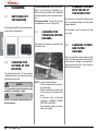
8.1
SWITCHING OFF
THE MACHINE
ENGLISH
Stop the machine with the three main switches,
moving them to the position 0.
Cleaning the work area: remove the worktop,
lifting it up from the front and sliding it out.
Remove the water collection dish underneath
and clean everything with hot water and cleansers.
Cleaning the bottom: To clean all the chromium-plated areas, use a soft, damp cloth.
8.3
CLEANING THE
STAINLESS COFFEEHOLDERS
The stainless steel showers are located under
the delivery units.
Fig. 22
8.2
WARNING
It is not possible to clean the machine using
water jets or standing it in water
WARNING
Do not use solvents, chlorine-based products or abrasives.
66
CLEANING THE UNIT
WITH THE AID OF
THE BLIND FILTER
The machine is set to wash the delivery group
with an automatic cleaning cycle and specific
powder detergent.
It is advisable to wash the machine at least
once a day.
8.5
CLEANING FILTERS
AND FILTERHOLDERS
Place two spoonfuls of special cleanser in half
a litre of hot water and immerse filter and filterholder (without its handle) in it leaving them to
soak for at least half an hour. Then rinse abundantly with running water.
CLEANING THE
OUTSIDE OF THE
MACHINE
The machine must be set to “O” power (switch
off and disconnector open) before any cleaning
operations are performed.
8.4
Fig. 23
NOTE: To clean proceed as follows:
7XUQWKHVFUHZSODFHGLQWKHFHQWUHRI
the coffee-holder.
6OLGHWKHFRIIHHKROGHURXWDQGFKHFN
that its holes are not obstructed but
clean.
,I REVWUXFWHG FOHDQ DV GHVFULEHG
(Paragraph “CLEANING FILTERS
AND FILTER-HOLDERS”)
We recommend cleaning the coffeeholder once a week.
9.
MAINTENANCE
NOTE: During maintenance/repairs, the parts
used must be able to guarantee compliance with the safety and hygiene
requirements envisaged for the device.
Original replacement parts can offer
this guarantee.
Regeneration procedures are as follows:
1) Turn the machine off and place a container
large enough to contain at least 5 litres
under tube E.
Turn levers C and D from left to right; take
the cap off by unscrewing knob and fill with
1 Kg normal kitchen salt.
C
C
IN
F
E
Fig. 27
OUT
RESIN AND
SOFTENER
REGENERATION
D
Fig. 25
To avoid scaling deposits in the boiler and in
the heating exchangers, the softener must
always be kept efficient.
Therefore, the ionic resins must be regularly
regenerated.
Regeneration times are established according
to the quantity of coffee delivered daily and the
hardness of the water utilised
These can be seen in the diagram included in
the following figure.
3) Reposition lever D towards the left.
G
C
C
D
Fig. 26
Fig. 28
Fig. 24
67
ENGLISH
NOTE: After the repair or replacement of any
components of parts that come into
contact with food or water, it is necessary to carry out the washing procedure
as described in point 1.4 or according
to the manufacturer’s instructions.
9.1
2) Put the cap back on and reposition lever C
moving it towards the left and allowing tube
F to discharge the salty water until it has
been eliminated and the water becomes
fresh again (about half and hour).
68
ENGLISH
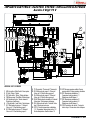
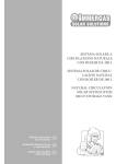
IMPIANTO ELETTRICO / ELECTRIC SYSTEM / INSTALLATION ÉLECTRIQUE
Aurelia II Digit T3 V
9
8
7
16
12
13
4
17
18
7
8
10
11
15
6
14
9
9
5
1
2
3
LEGENDA / KEY / LÉGENDE
1
2
3
4
5
MS Interruttore / Main Switch / Interrupteur.
R Relè / Relay / Relais.
RS Relè statico / Relay / Relais statique.
PM Motore pompa / Pump Motor / Moteur pompe.
HE Resistenza boiler / Heater element /
Résistance chauffe-eau.
6 LP Sonda livello / Level Probe / Sonde niveau.
7 EV1 Elettrovalvola gruppo 1 / Solenoid
Valve unit 1 / Electrovanne groupe 1.
8 EV2 Elettrovalvola gruppo 2 / Solenoid
Valve unit 2 / Electrovanne groupe 2.
9 TE Termostato / Thermostat / Thermostat.
10 EV3 Elettrovalvola gruppo 3 / Solenoid
Valve unit 3 / Electrovanne groupe 3.
11 EV4 Elettrovalvola gruppo 4 / Solenoid
Valve unit 4 / Electrovanne groupe 4.
12 EVHW Elettrovalvola miscelatore / Solenoid
Valve mixer / Electrovanne mélangeur.
13 EVL Elettrovalvola livello / Solenoid Valve
level / Electrovanne niveau.
14 STS1-2 Sonda temperatura scaldatazze
1-2 / Cupwarmer temperature probe 1-2 /
Sonde température chauffe-tasses 1-2
15 SPC Sensore pressione caldaia / Sensor
pressure boiler / Capteur pression chaudière.
16 RS1 Resistenza scaldatazze 1 /
Cupwarmer heating element 1 /
Résistance chauffe-tasses 1
17 RS2 Resistenza scaldatazze 2 /
Cupwarmer heating element 2 /
Résistance chauffe-tasses 2
18 CRS Connettore relè statici / Connector
static relays / Connecteur relais statiques.
101
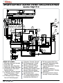
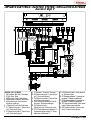
IMPIANTO ELETTRICO / ELECTRIC SYSTEM / INSTALLATION ÉLECTRIQUE
Aurelia II Digit T3 S
9
7
16
12
13
4
17
18
7
8
10
11
15
6
14
9
9
5
1
2
3
LEGENDA / KEY / LÉGENDE
1 MS Interruttore / Main Switch / Interrupteur.
2 R Relè / Relay / Relais.
3 RS Relè statico / Relay / Relais statique.
4 PM Motore pompa / Pump Motor / Moteur pompe.
5 HE Resistenza boiler / Heater element /
Résistance chauffe-eau.
6 LP Sonda livello / Level Probe / Sonde niveau.
7 EV1 Elettrovalvola gruppo 1 / Solenoid
Valve unit 1 / Electrovanne groupe 1 .
8 EV2 Elettrovalvola gruppo 2 / Solenoid
Valve unit 2 / Electrovanne groupe 2.
102
9 TE Termostato / Thermostat / Thermostat.
10 EV3 Elettrovalvola gruppo 3 / Solenoid
Valve unit 3 / Electrovanne groupe 3.
11 EV4 Elettrovalvola gruppo 4 / Solenoid
Valve unit 4 / Electrovanne groupe 4.
12 EVHW Elettrovalvola miscelatore / Solenoid
Valve mixer / Electrovanne mélangeur.
13 EVL Elettrovalvola livello / Solenoid Valve
level / Electrovanne niveau.
14 STS1-2 Sonda temperatura scaldatazze
1-2 / Cupwarmer temperature probe 1-2 /
Sonde température chauffe-tasses 1-2.
15 SPC Sensore pressione caldaia / Sensor
pressure boiler / Capteur pression chaudière.
16 RS1 Resistenza scaldatazze 1 /
Cupwarmer heating element 1 / Résistance
chauffe-tasses 1.
17 RS2 Resistenza scaldatazze 2 /
Cupwarmer heating element 2 / Résistance
chauffe-tasses 2.
18 CRS Connettore relè statici / Connector
static relays / Connecteur relais statiques.
IMPIANTO ELETTRICO / ELECTRIC SYSTEM / INSTALLATION ÉLECTRIQUE
Aurelia II Digit V
15
17
16
12
13
4
7
8
10
11
18
6
14
19
5
9
1
2
LEGENDA / KEY / LÉGENDE
1 MS Interruttore / Main Switch / Interrupteur.
2 R Relè / Relay / Relais.
3 RS Relè statico / Relay / Relais statique.
4 PM Motore pompa / Pump Motor / Moteur pompe.
5 HE Resistenza boiler / Heater element /
Résistance chauffe-eau.
6 LP Sonda livello / Level Probe / Sonde niveau.
7 EV1 Elettrovalvola gruppo 1 / Solenoid Valve
unit 1 / Electrovanne groupe 1.
8 EV2 Elettrovalvola gruppo 2 / Solenoid Valve
unit 2 / Electrovanne groupe 2.
9 TE Termostato / Thermostat / Thermostat.
10 EV3 Elettrovalvola gruppo 3 / Solenoid Valve
unit 3 / Electrovanne groupe 3.
11 EV4 Elettrovalvola gruppo 4 / Solenoid Valve
unit 4 / Electrovanne groupe 4.
12 EVHW Elettrovalvola miscelatore / Solenoid
Valve mixer. / Electrovanne mélangeur.
13 EVL Elettrovalvola livello /
Solenoid Valve level / Electrovanne niveau.
14 STS1-2 Sonda temperatura scaldatazze 1-2 /
Cupwarmer temperature probe 1-2 / Sonde
température chauffe-tasses 1-2
3
15 EVS Elettrovalvola sfiato / vacuum electrovalve / Electrovanne évent
16 RS1 Resistenza scaldatazze 1 / Cupwarmer heating element 1 / Résistance chauffe-tasses 1.
17 RS2 Resistenza scaldatazze 2 / Cupwarmer heating element 2 / Résistance chauffe-tasses 2
18 SPC Sensore pressione caldaia / Sensor pressure boiler / Capteur pression chaudière.
19 CRS Connettore relè statici / Connector static
relays / Connecteur relais statiques.
103
SCHEMA CALDAIA / BOILER DIAGRAM / SCHÉMA DE CHAUDIERE
Aurelia II DIGIT
Donnees de projet generateur de vapeur
Type
Type
Design pressure MPa
Pression MPa
Working pressure MPa
Pression de service MPa
Design temperature (C°)
Températures de projet (C°)
Working temperature (C°)
Températures de service (C°)
Fluid contained
Fluide contenu
Saturated water vapour
Vapeur d’eau saturée
Hydraulic test pressure MPa
Pression de test hydraulique MPa
Supply
Alimentation
Water pipes
Conduite d’eau
KEY
LEGENDE
MATERIAL
MATERIAU
Clips (sheet metal)
Bande (tôle)
Curved bottom
Fond bombé
Base – Flange
Fonde – Flasque
Cast OT
Fusion OT
Nozzles Flanges
Flasques Bocchelli
Cast OT
Fusion OT
Tubes and Stubs
Tubes
WELDING PROCESS
PROCEDE DE SOUDURE
A) TIG automatic between copper and copper (Cu DHP UNI 331)
A) TIG automatique entre cuivre et cuivre (Cu DHP UNI 331)
B) TIG automatic between copper and brass (Cu DHP UNI)
B) TIG automatique entre cuivre et laiton (Cu DHP UNI)
C) Oxy-fuel welding between copper (Cu DHP UNI 3310-72 Group 1) and brass (CuZn40Sni UNI 4891 Group 5c)
C) Soudure oxy-acétylénique en cuivre (Cu DHP UNI 3310-72 Groupe 1) et laiton (CuZn40Sni UNI 4891 Groupe 5c)
SAFETY VALVE
VANNE DE SURETE
See attached certificate
Voir certificat ci-joint
104
Capacité
Longueur
SCHEMA CALDAIA / BOILER DIAGRAM / SCHÉMA DE CHAUDIERE
Aurelia II T3 (3 Gr.)
List of Parts Liste des composants
ELEMENT QTY PART NO.
ELEMENT QTE NUMERO COMPOSANT
MATERIAL
MATERIAU
DESCRIPTION
DESCRIPTION
STANDARD
NORMES
Boiler body Aurelia 0.180 2 Gr II T3 Copper CIJ-DHP 99.9
Corps chaudière Aurelia 0.180 2 Gr II T3 Cuivre CIJ-DHP 99.9
Copper CIJ-DHP 99.9
Cuivre CIJ-DHP 99.9
Bevel gear D.180 2 holes
Coupe D.180 2 trous
BOILER FLANGE d 180
FLASQUE CHAUDIERE d 180
Coupling 3/8” Male OT57 CW51DL
Prise 3/8” Mâle OT57 CW51DL
Elbow for welding 3/8 M OT57 CW51DL
Coude à souder 3/8 M OT57 CW51DL
Steam inlet coupling OT 57 CW51DL
Prise vapeur OT 57 CW51DL
Pipe D16X1
Tube échangeur D16X1
Copper CIJ-DHP 99.9
Cuivre CIJ-DHP 99.9
PROJECT DATA FOR DIRECTIVE PED 97/13/EC
DONNEES PROJET DIRECTIVE PED 97/13/CE
VOLUME
VOLUME
Coupling G1-8 F through OT57 CW510L
Prise G1-8 F passante OT57 CW510L
Material Matériau
Copper, brass
Cuivre, laiton
Treatment
Traitement
Tolerance
Tolérance
Pickling
Décapage
Average
Moyenne
Description Description
Scale
Echelle
Date Date
Caldaia Boiler Chaudière
Description
Description
Code
Designer
Concepteur
Code
FLUID
FLUIDE
105
SCHEMA CALDAIA / BOILER DIAGRAM / SCHÉMA DE CHAUDIERE
Aurelia II T3 (2 Gr.)
List of Parts
ELEMENT
ELEMENT
QTY PART NO.
QTE NUM. COMPOSANT
Liste des composants
DESCRIPTION
DESCRIPTION
MATERIAL
MATERIAU
STANDARD
NORMES
Boiler body Aurelia 0.180 2 Gr II T3 Copper CIJ-DHP 99.9
Corps chaudière Aurelia 0.180 2 Gr II T3 Cuivre CIJ-DHP 99.9
Bevel gear D.180 2 holes
Coupe D.180 2 trous
Copper CIJ-DHP 99.9
Cuivre CIJ-DHP 99.9
Pipe D16X1
Tube échangeur D16X1
Copper CIJ-DHP 99.9
Cuivre CIJ-DHP 99.9
BOILER FLANGE d 180
FLASQUE CHAUDIERE d 180
Steam inlet coupling OT 57 CW51DL
Prise vapeur OT 57 CW51DL
PROJECT DATA FOR DIRECTIVE PED 97/13/EC
DONNEES PROJET DIRECTIVE PED 97/13/CE
Elbow for welding 3/8 M OT57 CW51DL
Coude à souder 3/8 M OT57 CW51DL
Coupling 3/8” Male OT57 CW51DL
Prise 3/8” Mâle OT57 CW51DL
VOLUME
VOLUME
Coupling G1-8 F through OT57 CW510L
Prise G1-8 F passante OT57 CW510L
Material Matériau
Copper, brass
Cuivre, laiton
Description
Caldaia Boiler
Description
Treatment
Traitement
Tolerance
Tolérance
Pickling
Décapage
Average
Moyenne
Date Date
Description
Chaudière
Description
Designer
Concepteur
106
Scale
Echelle
Code
Code
FLUID
FLUIDE
SCHEMA CALDAIA / BOILER DIAGRAM / SCHÉMA DE CHAUDIERE
Aurelia II T3 (2 - 3 Gr.)
List of Parts Liste des composants
ELEMENT
ELEMENT
DESCRIPTION
DESCRIPTION
QTY PART NO.
QTE NUM. COMPOSANT
MATERIAL
MATERIAU
Flange Pr machined, stainless steel +1 Microbar STAINLESS STEEL
AISI316L
Flasque Pr finition inox +1 Microbar
Flange 4 holes machined, stainless steel Microbar STAINLESS STEEL
AISI316L
Flasque 4 trous finition inox Microbar
Stainless steel pipe D.76.1 sp1.5 Aisi 316L
Tube inox D.76.1 ép.1.5 Aisi 316L
STAINLESS STEEL
AISI316L
Heating element for welding 1000W 230V
Stainless steel version 2009 (Dwg. GGS63597)
Résistance à souder 1000W 230V Inox
version 2009 (Dessin GGS63597)
Stud M3x8 stainless steel
Boulon prisonnier M3x8 inox
STAINLESS STEEL
Bulb support tube microbar stainless steel STAINLESS STEEL
Tube porte-bulbe Microbar Inox
Stud M4x15 stainless steel
Boulon prisonnier M4x15 Inox
STAINLESS STEEL
Material Matériau
Stainless steel Aisi 316L
Acier inox Aisi 316L
Description
Description
Boiler
Chaudière
Description
Treatment
Traitement
Tolerance
Tolérance
Scale
Echelle
media
Average
Moyenne
Date Date
Description
Designer
Concepteur
Code
Code
Note: Boiler in application area, article 3, section 3 97/23/CE
Note: Chauffe-eau dans zone d’application article 3, alinéa 3 97/23/CE
107
108
109
110
Ed. 02 del 02/2014
Codice 31000386
Nuova Distribution Centre
LLC 6940Salashan PKWY BLDG A 98248
Ferdale, WA
Via M. d’Antegiano, 6
62020 Belforte del Chienti
Macerata Italy
Tel. +1.360.3662226
Fax +1.3603664015
videoconf.+1.360.3188595
www.nuovasimonelli.it
[email protected]
Tel. +39.0733.9501
Fax +39.0733-950242
www.nuovasimonelli.it
E-mail: [email protected]
Graphics and printing by: X TYPE ENGINEERING S.r.l.
La Nuova Simonelli si riserva di apportare tutte le modifiche ritenute necessarie.