1
4 - Emulator Features
ST7MDT5-EMU2B Emulator User Manual
core and gives access to all on-chip peripherals.
•
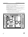
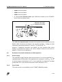
Control logic: Control logic is provided to manage the software execution by
the user (i.e. program running and halting).
•
Application VCC follower: The probe emulation MCU is supplied with the
same voltage as the application (i.e. must be in the range 4.5 V to 5.5 V).
•
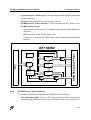
ST7 HDS2 interface: All of the communication buses connecting the active
probe to the ST7 HDS2 board are buffered:
-
ST7 Address bus (16-bit) of the ST72141 in emulation mode.
-
Data bus (8-bit) of the ST72141 in emulation mode.
-
ST7 emulation chip control bus for trace breakpoints and memory mapping.
Data
Clock
Source
Control/Status
Control
PLD
Automaton
Control
Decoder
Data
ST7-Addresses
Emulation Signals
I/O
Periph.
Device
Adapter
I/O, Peripherals
Addresses
Power Supply
Application Follower
ST7MDT5 Control
46/65
ST7
Emulation
MCU
ST7MDT5 MCU Adapter
Application Board
Data
Data
ST7-Data
Addresses
HDS2 Dedication Board
ST7 ACTIVE PROBE