1
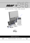
PRO-LD
DIALLER ALARM SYSTEM
Installer Manual
Quality
Endorsed
Company
ISO9001
LIC.No. QEC2074
NSW Head Office only
Ness Security Products Pty Ltd ACN 069 984 372
SYDNEY
02 8825 9222
MELBOURNE
03 9878 1022
BRISBANE
07 3343 7744
WWW.NESS.COM.AU
N55
PERTH
08 9328 2511
ADELAIDE
08 8277 7255
NZ (NFS SECURITY)
©2000 Ness Security Products Pty Ltd. All rights reserved.
PRO-LD Installer Manual V3.0
To the best of our knowledge, the information contained in this manual is correct at the time of
going to print. Ness Security Products reserves the right to make changes to the features and
specifications at any time and without notice in the course of product development.
64 9 573 0401
HONG KONG
852 2721 8097
INTRODUCTION
The PRO-LD local alarm has been designed to provide you, the installer, with
all your most requested features including, ease of installation, ease of
programming and user friendly operation in a package which is functional and
attractive.
The new patented PRO Series polycarbonate cabinet continues NESS
Security Products’ commitment to innovative design and quality,
incorporating features never before seen in this type of product.
The PRO-LD is an Australian designed and built product which is available at
an affordable price without compromising quality or features.
This manual will tell you all that you need to know about installing and
programming the PRO-LD. For information about operating instructions,
refer to the PRO-L User’s Manual.
PACKAGE CONTENTS
The PRO-LD package contains the following;
l
1 x PRO-LD Control Board
l
1 x PRO Series Cabinet
l
1x
l
1x
Transformer
l
10 x
End-of-Line Resistors
l x Spare
Rechargeable Battery
or
Fuse
l x PRO-LD Keypad
l x PRO-L Zone List
l x Conduit Clip
l
l x Installation Manual
l x User Manual
l
1 x Telephone Lead
PRO-LD
DIALLER TELEPHONE CONNECTION
MOM 3/S SOCKET
PROUI PLUG
Pf?o-ul
The PRO-LD dialler connects to a
telephone line via a Mode 3 or 5 socket.
A Mode 3 or 5 connection allows the
dialler to cut-off any existing devices
(e.g. phones, faxes) and “seize” the
Telephone line for it’s own use, this is to
ensure secure operation.
If a mode 3 or 5 socket is not available
on site then a mode 3 double adaptor
which allows for a phone and a dialler to
be connected can be purchased from
retail outlets.
The dialler must always be connected directly to the incoming phone line,
connection to a PABX line will either dramatically lessen your security and
increase your problems, or in some cases the dialler will not work at all e.g. a
Telecom Commander System does not allow you to connect to the extension lines.
The PRO-LD carries in Australia the Austel Permit A92/03/0365 Please note that
under the Telecommunications Act 1991 it is illegal to tamper with or to wire into
the tiers network for connection of telephones, diallers, Securitel devices etc.
unless the work is carried out by or under the supervision of an Austel licensed
wiring technician. Breaches of the Telecommunications Act leave the installer
liable to prosecution with penalties of up to $12,000 per offence and immediate
disconnection of any illegally wired devices.
Your attention is also drawn to the Act which states that where a permitted
alarm device is connected to a carriers network all cabling including
connection to Keypads, Detectors etc. shall be carried out to Austel Technical
Standards using Austel approved cable only.
Note - wiring of the alarm system cables apart
the telephone line
connection does not require an Austel licensed technician to carry out the
work.
INPUTS
ZONE INPUTS -The PRO-LD has 9 separate monitored inputs
8 x programmable zones
1 x Tamper
Each input must be terminated with a 2k2 (2,200 ohm) end-of-line resistor as
supplied.
The input resistor tolerance is plus 1,200 or minus 900 ohms. Two end-of-line
resistors may be used to secure two cable runs on one zone. See below for
connection details.
POWER - AC input - Connect the brown and blue wires (no polarity) from
the NESS Plugpak to the AC terminals. The PRO-LD requires an A.C.
transformer rating of 1.4A @ 16VAC minimum.
BATTERY - Connect a sealed lead acid rechargeable 12V battery with a
minimum capacity of 2.4 Ah to these terminals. Charge current is limited to
350 mA maximum. Charge voltage is factory preset at 13.8V via pot V 1.
EARTH - For maximum protection against damage caused by lightning
strikes to the phone line, connect a good earth to the earth terminal of the
PRO-LD. The PRO-LD incorporates two 600 Volt Gas Surge Arresters from
each phone line to earth and a 275 Volt M.O.V. surge arrestor across the two
lines.
8
NESS Security Products
OUTPUTS
12V OUTPUTS - A regulated 13.8V dc output is available to power detectors
etc.
This output is available from two sets of terminals marked "+12F2" and “OV”.
It is fused by fuse F2 (1 .5A or 1.6A fastblow 2AG). A maximum load of 1A
may be connected to these terminals.
SIREN - An oscillating output,
via Fl (1
or 1.6A fast blow 2AG) for
connecting horn speakers. (3 x 8 ohm horns or 1 x 8ohm plus 1 x 4ohm)
STROBE - A latched 12Vdc voltage output, fused via F3 (1.5A or 1.6A fast
blow 2AG), for connecting strobes or piezo sirens.
RESET - A non-latched 12V dc voltage output controlled by the Siren Timer,
P29E and fused via F3 (1 .5A or 1.6A fast blow 2AG) for connecting piezo
sirens, relays etc.
Note: A total of 1.5A or 1.6A continuous is available from the reset and strobe
terminals.
SAT - The SAT terminal can be used to trigger satellites that require a highgoing-low input. The SAT voltage is nominally 13.8V via a 2k2 ohm resistor
and less than 2V in alarm.
J7 OUTPUTS - The outputs are open collector (switched negative) which can
supply a maximum 50mA Outputs available are:- Area 1 (armed), Area 2
(armed), Alarm 1, Alarm2, Tamper, Exclude, Battery low, Mains off, 12V (ext.
power).
The J7 outputs can be used to trigger external relays, or drive LEDs. The
Alarm 1, Alarm 2, Tamper and Exclude outputs latch until reset by a code.
The siren relay and satellite outputs turn on for the alarm reset time or until
reset by a code.
J6 LISTEN PINS - Connect any 8 ohm(or greater) speaker to these pins to listen
to the dialler progress. This is useful for fault fading .
9
PRO-LD REMOTE KEYPAD
Installation
Unclip the housing using a screwdriver to lever off the top half. Push the
screwdriver hard into each of the two holes in turn and lever upwards. Unplug
the keypad tail from the circuit board connector.
Remove the PCB by lifting off the 2 retaining rubber grommets and lifting the
PCB out.
Screw the base to the wall using the 2 mounting holes provided. These holes
match a standard switch plate spacing.
Clip the board back into the base bringing the 4 connecting wires through the
cable entry hole. Plug the rubber grommets back onto the posts provided.
Connect the wires to the screw terminals or solder them to the B 1 solder pads.
Plug the keypad tail onto the PCB and clip the top half onto the base by first
engaging the bottom clips and swinging the top closed, push hard to ensure the
clips engage.
Stick the zone list to the inside of the hinged lid. Clip the hinged lid onto the
keypad.
Wiring
The PRO-LD Keypad connects to the PRO-LD Control Panel via a 4 wire
connection. (See page 11)
A maximum of 5 keypads can be connected, each wired in parallel.
The maximum cable run is 100m using 14/0.20 cable. If you want to share a
cable run, then divide 100m by the number of keypads to be connected. e.g. 2
keypads on the one cable reduces the maximum run to 50m.
12
NESS Security Products
Armed LED Option
The Armed LED on the PRO-LD Keypad can be selected to indicate one of 4
options;
1/
2/
3/
A1A - Area 1 armed
A2A - Area 2 armed
A1B - Area 1 OR Area 2 Armed
A2B - Area 1 AND Area 2 Armed only
Select the option required by placing the jumper on J2 connector on the
appropriate pins. The Keypad comes with the jumper preset to the A 1B
position. ie. the armed LED will light when Area 1 OR Area2 are armed.
For split system operation with separate keypads, use option 1 (Area 1) and 2
(Area 2) on each Keypad respectively.
NOTE: It is possible to hard-wire your own LEDs if you require more than
the one. Details are available from NESS.
0
0
WIRING DETAILS
PANEL
PRO-LD
13
PROGRAMMING OPTIONS SUMMARY
User and Install Mode Access
Access Code 1 - (master) .......................... P11E
Access Code 2 ......................................... P12E
Access Code 3 ......................................... P13E
Access Code 4 ......................................... P14E
Access Code 5 ......................................... P15E
Access Code 6 ......................................... P16E
Access Code 7 ......................................... P17E
Access Code 8 ......................................... P18E
Access Code 9 ......................................... P19E
Access Code 10 ....................................... P20E
Access Code 11 ....................................... P21E
Access Code 12 ....................................... P22E
Access Code 13 ....................................... P23E
Access Code 14 ....................................... P24E
Access Code 15 ....................................... P25E
Entry Time1 .............................................. P26E
Entry Time2 .............................................. P27E
Exit Time ................................................... P28E
User and Install Mode Access
Alarm Time (Reset) ...................................
Normal Sens Zones ..................................
VIB SENS 1 Zones ...................................
VIB SENS 2 Zones ...................................
VIB SENS 3 Zones ...................................
VIB SENS 4 Zones ...................................
VIB SENS 5 Zones ...................................
VIB SENS 6 Zones ...................................
VIB SENS 7 Zones ...................................
VIB SENS 8 Zones ...................................
DoubleTrigger Zones ................................
Instant Zones ............................................
Entry 1 Zones ...........................................
Handover Zones .......................................
Entry 2 Zones ...........................................
Lockout Zones ..........................................
Assign Area1 Zones .................................
Assign Area2 Zones .................................
Area1 Active Codes 1 - 8 ..........................
Area1 Active Codes 9 - 15 ........................
Area2 Active Codes 1 - 8 ..........................
Area2 Active Codes 9 -15 .........................
Monitor Zones ...........................................
24 hr Zones ..............................................
Day Zones ................................................
Reset Output Zones ..................................
Strobe Output Zones ................................
Sonalert Output Zones ..............................
Siren Output Zones ..................................
AL 1 Output Zones ...................................
AL2 Output Zones ....................................
14
P29E
P30E
P31E
P32E
P33E
P34E
P35E
P36E
P37E
P38E
P39E
P40E
P41E
P42E
P43E
P44E
P45E
P46E
P47E
P48E
P49E
P50E
P51E
P52E
P53E
P54E
P55E
P56E
P57E
P58E
P59E
Miscellaneous ........................................... P60E
I Entry warning Beeps
2 Keyswitch monitor mode
3 Keyswitch Arming
4 Tamper siren lockout
5 Duress Reset Output
6 Auto Exclude Zones
7 Disable LEDs
8 O/P (A1 & A2) on after Exit
Tamper & Panic Outputs .......................... P61E
1 Tamper to Reset
2 Tamper to Strobe
3 Tamper to Sonalert
4 Tamper to Siren
5 Panic to Reset
6 Panic to Strobe
7 Panic to Sonalert
8 Panic to Siren
Shortcuts .................................................. P62E
1 Memory Display shortcut
2 Exclude shortcut
3 Monitor Arm shortcut
4 Panic shortcut
5 Area1 Arm shortcut
6 Area2 Arm shortcut
7 2 sec siren warning Auto Exclude
8 Exit Time x 10
Day & Monitor Outputs ............................ P63E
1 Monitor Reset Output
2 Monitor Strobe Output
3 Monitor Sonalert Output
4 Monitor Siren Output
5 Day Reset Output
6 Day Strobe Output
7 Day Sonalert Output
8 Day Siren Output
Miscellaneous ........................................... P64E
1 2 second Monitor Alarm
2 2 second Day Alarm
3 Pre-Alarm Monitor
Upload from Panel ................................... P96E
Download to Panel .................................... P97E
Return to DefauIt (only AccessCodes 1 - 15) . P98E
Program Installation Code ......................... P99E
PRO-LD
DIALLER OPTIONS SUMMARY
Telephone No. 1 (numeric entry only) ........ P70E
Telephone No. 2 (numeric entry only) ........ P71E
Client Code 1 ............................................ P72E
Client Code 2 (Used for Area 2 Open/Close) .......... P73E
Report Zone alarms ..................................
Report Miscellaneous Alarms ...................
Report Zone alarms Restored ...................
Report Miscellaneous alarms Restored .....
Report Multiple Zone Alarms .....................
Zone Mapping to Client Code ....................
P74E
P75E
P76E
P77E
P78E
P79E
Telephone No. 1 (inc *, #, and Pause) ....... P80E
Telephone No. 2 (inc *, #, and Pause) ....... P81E
Area Zone Restore Reports ...................... P82E
1 Immediately on Input resealed
2 After Siren Reset
3 After Opening + Input Sealed
4 After Opening Always
Time between Test Calls (2 hr steps) ........ P83E
Time before first Test Call (2 hr steps) ...... P84E
Dialling Method ......................................... P85E
1 Automatic
2 Decadic (pulse) Dial
3 V.F. (DTMF) Dial
Miscellaneous Reporting ........................... P86E
1 Ademco Extended/Audible Format
2 Enable Test Calls
3 Delay Mains Fail by 1 Hour
4 Ademco Extended (no checksum)
Miscellaneous Dial .................................... P87E
1 Split Dial or Alternate
2 Dial without Dial tone
3 New Zealand Dial
4 4 or 10 Dial Attempts
Miscellaneous Open/Close ....................... P88E
1 Send Area 1 Open/Close
2 Send Area 2 Open/Close
3 2 Sec. Siren on Closing
4 2 Sec. Strobe on Closing
PRO-LD
15
PROGRAMMING
Access To Program Modes from Initial Power Up
When power is applied for the first time with the box tamper open,
the panel will enter Install Program Mode (3 beeps + Prog light flashing)
Access To Program Mode from Operating Mode
The Panel must be fully disarmed (no area, no monitor on). Press
You are now in User
<MASTER-CODE
beeps Prog light ste
de. Then to enter Ins
<INSTALL CODE>
(3 beeps - Prog led flashing) Note: Default install code is 000000
NOTE: For security purposes, the Install Code on its own will not allow
access to Install Program mode. The Master Code must be entered first.
How To Program
The program sequence always follows this pattern;
<2 digit option>
eps if OK, 1 long
(
The lights will display status or value.
Enter the new val
<New Value?
t
Display new value, 3 beeps
To Clear Programme Information
(from install mode only)
Press;
P 98 E to clear access codes 1 to 15
NESS Security Products
LOCAL DOWNLOAD/UPLOAD
The PRO-LD control panel contains a unique method of programming or
storing all of its programmable options onto a tiny board called the PRO
LDU.
The PRO LDU allows you to upload an existing program (for servicing,
storage or use as a master program key) from a PRO-LD panel. Alternatively
you can take an existing program stored on a PRO LDU and download it into
a PRO-LD. Use of the PRO LDU can save time in programming (you could
keep 4 or 5 commonly used programs since the information is non-volatile and
will last up to 10 years in storage) and will save time when servicing.
To use the PRO LDU1. Plug the PRO LDU onto J3. The LED will light on the LDU to
show correct connection,
2. Place the PRO-LD panel into install program mode,
3. To upload or store a program to the PRO LDU, press P96E The
PRO-LD programmed options are copied to the PRO LDU
4. To download a program from the PRO LDU to the PRO-LD,
press P97E. The PRO LDU options are copied to the PRO-LD.
Write Protection
The PRO LDU has a link which is accessible from the top of the board.
Remove the link to write protect the stored information on the PRO LDU.
This will prevent accidental erasure of information you wish to keep.
PRO LDU
Jumper
OPTION DESCRIPTIONS
Codes
The PRO-LD has a total of 16 operator codes. One code is the installer access
code and is used only for access to Installation Program Mode. The remaining
15 codes are used for arming/disarming etc. These codes are assigned user
numbers 1 to 15 (options 1 l-25).
- User 1 is the master code. The master code is the only code which can
access User Program Mode.
- Codes can be 3 to 6 digits in length.
- User codes cannot start with " 0 "
To clear an existing code you must re-program that code with a number
that starts with “0”.
For more information on codes see “PRO-L User Manual”
The installer code is defaulted to “000000” (option 99), this is an optional
code.
To Clear codes, use P98E in Install Program Mode.
Area Operation
The PRO-LD Control Panel allows for the 8 zones to be split into two groups
known as Area 1 and Area 2. The two Areas can be assigned access codes so
that a user may have access to either Area 1 or Area 2 or both Areas. This
allows for partial Arming of the premises or protecting two separate premises
with one PRO-LD. (Eg,. Petrol Station and Workshop.) Options 45-50 are
used to assign zones and codes to Areas. The default is all codes and all zones
selected to Area 1.
Arming and Disarming is carried out as normal. You may install a Keypad in
each Area with its own Armed Led. (See page 11.)
Area operation only applies to zones when they are in the armed state, this
means that day, 24hr and monitor zones are independent of the area operations.
18
NESS Security Products
Zone Assignment
All zones can be programmed to operate in all 3 Panel Modes i.e. a Night
Zone, as well as Monitor Zone and also a Day Zone. These zones must always
exist in Area 1 or Area 2 to operate. These Zones can be programmed to turn
on different outputs for each Mode of panel operation when they alarm.
These zones can also be programmed to be one of 4 types; Instant, Handover,
Entry Delay 1 and Entry Delay 2.
Zones may be programmed to operate as 24 Hour Zones where they
automatically operate in all of three modes (Night, Monitor, Day). These zones
work independently of Area 1 and 2. Therefore, a 24 Hour zone cannot be
selected in an Area. When alarmed, these zones will always turn on the same
outputs regardless of the Panel Mode. 24 Hour Zones are always Instant.
ZONE MAPPING OPTIONS
Only One Per Zone
20
NESS Security Products
I
I
I
I
ZONE TYPE DESCRIPTION
Instant Zones P40E
Instant zones operate only in the Armed state. When Armed, these zones will
not operate for the programmed exit time (P28E). At the expiry of exit time
these zones will activate assigned outputs immediately if they are alarmed.
Entry 1 Zones P4lE (l-99 seconds)
Entry 1 zones operate only in the Armed state. When Armed these zones will
not operate for the programmed exit time (P28E). At the expiry of exit time
these zones will activate an entry 1 timer (P26E) if they are alarmed. If the
entry 1 timer is activated a code must be entered to reset the timer. If not reset
at the expiry of the entry 1 timer, the entry 1 zone outputs will be activated.
NOTE: During entry 1 timer activation the sonalert will BEEP as a pre-alarm
warning. To disable entry beeps, program P60E 1E
Entry 2 Zones P43E (10 - 990 seconds)
As per entry 1 above but utilising entry 2 timer (P27E) which is set in 10
second increments instead of 1 second increments. Eg. 60 secs = 6
Handover Zones P42E
Handover zones operate as per “Instant” zones above with the exception that
if either one of entry 1 or 2 timers has been activated then the handover zones
will be inoperative for the duration of those times.
NOTE: Zone alarms (other than Day and 24hrs) can only be reset by a code
assigned to the Area that the zone alarm occured in, however the siren output
can be reset by any valid code.
24 Hour Zones P52E
24 hour zones operate at all times regardless of the mode of panel operation,
ie. Armed, Disarmed or Monitor. When alarmed, these zones will activate
assigned outputs immediately.
To reset those alarms any valid user code must be entered.
PRO - LD
21
Dav Zones
Day zones operate only when the panel is in a totally disarmed state, ie. no
areas Armed or Monitor on. When armed, these zones will activate the
assigned outputs immediately (instant operation).
-If
2E is selected, Day Zones will turn on the outputs assigned by
Option 63 for 2 seconds. This is useful for daytime
monitoring.
-If
2E is not selected then the Day Zones will turn on the outputs
assigned to the zones (option 54-59). The outputs will behave as normal. Use
this setting for dedicated Day alarm zones.
Monitor Zone
Monitor zones are used primarily for securing perimeter or high risk zones
while a residence is occupied. Monitor mode allows a user to Arm those
zones with a simple keypad operation. Monitor zones will only operate when
the panel is in the Monitor mode i.e. Armed LED flashing.
If
is selected then the Monitor zones will turn on the outputs
assigned by option 63 for 2 seconds.
If
is not selected then the Monitor zones will turn on the outputs
assigned to the zones (option 54-59). The outputs will behave as normal.
If
3E is selected then the Monitor zones will all behave as Entry/Exit
zones. This allows the user to have a
pre-alarm warning of a monitor
If
3E is not selected then the Monitor zones will behave as
programmed for the zone types (options
Siren Lockout
All 8 zones and tamper input can be programmed to lockout, ie. cause the
siren to sound only once whilst the panel is armed. The siren is “locked out”
for that zone until the panel has been reset by entering a valid code.
DEFAULT = ALL ZONES LOCKOUT
Tamper is defaulted to lockout. If you wish to change it, program
4E
NOTE: Only the first zone to cause an alarm will lockout while the sirens are
sounding.
22
Security Products
Sensitivity P38 - 39E
The 8 zones of PRO-LD can be programmed with one of 9 sensitivities.
Normal, (P 30 E), the zone must be unsealed for 200ms continuously.
Vibration Sensitivities 1 to 8 (P 3 1-38 E). This is used with “Nessensors”.
Sensitivity 1 is the most sensitive and sensitivity 8 the least sensitive.
NOTE: Sensitivity 1 and 8 should not normally be used, they are provided as
a guide to the upper and lower limits only.
Double Trigger P39E
All 8 zones can be programmed to be double trigger, ie. the zone has to alarm
twice within 4 minutes before the panel will recognise an alarm condition.
The PRO-LD also incorporates our unique setting, whereby if any 2 zones
which are programmed to be double trigger, alarm once each, an alarm is
generated so as to not to lessen security.
NOTE: If a double trigger zone is left unsealed for longer than 15 seconds
then an alarm is generated as a safety override.
ON = YES
DEFAULT
PRO - LD
I
23
Output Assignment P54 - 59 E. P61 & 63 E
When a zone alarms, it can turn on any or all of the following 6 outputs;
Sonalert, Strobe, Siren, Reset, AL 1, AL 2. The programming is selected with
options 54-59. Simply set the zone number to the output to select it. The zone
LED will indicate if the zone is selected.
The Tamper input and the Keypad Panic can be programmed to turn on the
Reset, Strobe, Sonalert and Siren. Programming is achieved using option 6 1.
Monitor and Day are assigned in the same manner using option 63. Tamper
and Monitor outputs are displayed on zone LEDs 1-4 while Panic and Day
outputs display on zone LEDs 5-8. (See table below)
OUTPUT MAPPING
Option Output
58
Zones
AL 1
NOTE: the Reset, Siren and Satellite output will turn on for the duration of
the alarm timer (P29E) or until it is reset via a valid code. The Strobe, AL 1
and AL 2 outputs latch until reset by a valid code.
Kev Operation Shortcuts P62E
Keypad operations can be programmed to operate with or without (shortcut)
a user code. The operations available are; entry to Monitor mode, Exclude
and Memory modes, Arming and keypad Panic. The default is Arm with
code, all other operations shortcut.
Operations With Code, example;
To Arm, press <ARM> <CODE NO> <ENTER>
Operation Short Cut, example;
To Arm, press <ARM> < ENTER>
NOTE: Never program Arm Area 1 and Area 2 shortcut (5E & 6E) together
without allocating an access code to Area 2. If you do so and Arm both areas,
Area 2 will remain armed which will bar entry into program mode until Area 2
is disarmed.
24
NESS Security Products
Kevswitch P60E 2E 3E
A normally open momentary keyswitch can be used to Arm, Disarm or change
the PRO-LD to Monitor mode.
If a keyswitch is required it is wired to zone 8 as shown (obviously zone 8 is
no longer used as an alarm input)
NC.
C
Z8
Option 60, 2 or 3 must be programmed to allow keyswitch operation.
Option 2 allows change to Monitor or Disarming only, on each momentary
keyswitch contact of greater than 200 ms.
Option 3 allows Arming and Disarming only, on each momentary keyswitch
contact of greater than 200ms
If Option 2 and Option 3 are both programmed, the Panel will cycle through
all three operating modes on each 200ms keyswitch contact, ie.
NOTE: Momentary keyswitch operation allows for more than 1 keyswitch to
be used - just add more switches in parallel. If the input is opened, a full alarm
will occur. Use this feature to add an additional panic button in series with the
2k2 resistor.
WARNING - The Keyswitch will Am and Disarm Area 1 and Area 2. Always
Disarm both Areas to allow entry to Program Mode.
PRO -
25
Auto Exclude P60E 6E
Zones are programmed to auto exclude (no alarm) if they are unsecured at the
end of exit time. If you require the zone to alarm if unsecured at the end of
exit then unset P60E 6E.
End of Exit/Auto Exclude Warning P62E 7E
If you require a 2 second siren burst at the expiry of exit time to indicate a
faulty auto excluded zone, then program P62 7E.
l
Duress
To generate a silent duress alarm (ie. an alarm to indicate a forced disarm),
simply prefix an existing user code with either digits 5, 6, 8 or 9 (when
disarming). eg. to Disarm normally, press 2391 <ENTER>. To Disarm with a
Duress, press 52391 <ENTER>. The duress alarm can be programmed to
activate the Reset output (option 60E 5E)
Keypad Tamper
A keypad tamper alarm will be generated after 4 successive attempts to enter
an invalid code. The keypad tamper alarm outputs are the same outputs as
programmed to external tamper.
Extended Exit Time P62E 8E
If you require a longer than normal exit time you can multiply your exit time
(P28E) by 10 by programming P62E 8E.
e.g. P28E = 22 seconds if P62E 8E is set then exit time = 22 x 10 = 220
seconds.
Display Disable P60E 7E
The LED indicators on the keypad can be programmed to blank after 4
minutes of no keypad use (useful to stop annoying lights in a bedroom). To
blank the display program P60E 7E. Beeps, or pressing any key will restore
the display. (Use <ENTER> preferably.)
Area 1 and Area 2 Outputs P60E 8E
The outputs marked area 1 and area 2 on connector J7 turn on immediately
Area 1 or Area 2 are armed. If you require them to turn on only after exit time
has expired then program P60E 8E
26
NESS Security Products
DIALLER OPTIONS
The PRO-LD Control Dialler communicates all of its alarm information via a
standard telephone line to a Central Monitoring Station using Ademco
Extended High Speed Format.
To minimize the amount of programming required to make the dialler operate
correctly, all of the available alarms have been allocated to fixed channels and
cannot be re-programmed. You will find in practice that since only 15 Alarms
are available for transmission and the Ademco format allows for 16 Alarm
channels to be transmitted, it is not necessary to re-map these channels. All
re-mapping can be handled at the Central station. All of the 15 alarms are
reported on client code 1.
The table below indicates the allocation of Alarm channels in the PRO-LD;
I
With 9th CHANNEL = 7
(CHANNEL 1 - 8)
ZONE
CHANNEL
1
1
2
3
4
5
6
7
8
2
3
4
5
6
7
8
With 9 t h CHANNEL = 1
(CHANNELS 9 16)
MISC. ALARM
CHANNEL
ID uress
I
1
Keyswitch Panic
2
Keypad Panic
3
Spare
4
Panel Tamper
5
External Tamper
6
Keypad Tamper
7
Instal Prog. Entry
8
PRO LD
27
Telephone No. 1 P70E
P 70 E Telephone no. E
Telephone No. 1 may be up to 14 digits only ( 0, 1-9). This is the Main
telephone number for your central monitoring station.
If you require pauses or the V.F. digits * or # to appear in your number then
use program option P 80 E. To clear telephone No. 1 program option P80E.
Telepone No. 2 P71E
P 71 E Telephone no E
Telephone number 2 may be up to 14 digits only ( 0, l-9). This is the back-up
telephone number for your central monitoring station and is optional.
If you require pauses or the V.F. digits * or # to appear in your number then
use program option P 8 1 E. To clear telephone No. 2 program option P8 1E.
Client Code 1 P72E
P 72 E digit code E
This is the identification code for all alarms and Area 1 open/close reports.
Client Code 2 P73E
P 73 E digit code E
This number is only used to report Area 2 Open/Close messages. Program this
code if Area 2 Open/Close reports are to be sent.
Dialler Disable
If you wish to disable the Dialler functions altogether, clear telephone No. 1
(see P80E). This may be useful if you want to enable monitoring at a later stage.
28
NESS Security Products
Telephone No.s 1 & 2 with Pauses, * and # P80E P81EPP
P 80 E or P 8 1 E Telephone no, P, extra digit E P P
To program Pauses of 1.6 second duration and or the V.F digits * or # then a
special programming method is used which is unique to the Telephone
programming only. To include one of the special digits in the telephone
number programming you must first press the Program key (this works like a
Shift key on a calculator) and then Digit 1, 2 3 or 0. Where:
1 = 1.6 Second pause.
2 = V.F. *
3 = V.F. #
0 = Clear the number.
When you have finished programming your telephone number by pressing
Enter, you must also press the Program key twice to save the new values.
Example 1
To program Telephone number one with 624-3655 starting with a 0 to access a
PABX with a pause after the 0 then press;
P80E 0 P1 6 2 4 3 6 5 5 E P P .
Example 2
To program Telephone number two with a Telecom Easy Dial number 23
ending with a *, then press;
P81E 2 3 P 2 E P P .
When the PRO-LD displays the telephone number, the following lights are
used to display the special digits;
= TAMPER LED
PAUSE
*
= LINE LED
#
= ARM LED
Example 3 To clear Telephone No. 1 then press,
P80E PO E PP
NOTE: If both telephone numbers are cleared, then all dialler reporting is
disabled. If telephone number 2 is disabled, all calls are made on
telephone number 1 and the setting of P87E 1E has no effect. To view
telephone No. 1 or No. 2 use P70E or P7 1E.
WARNING - If you enter P80E or P81E you must press the Program key twice
to exit the special program mode - even if you don’t want to program anything.
PRO - LD
29
Alarm Reporting P74 - 79 E
The zone alarms and the miscellaneous alarms may be selected to ;
Report/Don’t Report, Send Restores/Don’t send Restores,
and Send Multiple
.
alarms/Don’t send Multiple alarms.
Option P79E allows you to select which Client Code to report the Zone alarms
and excludes to. If the Zone LED is OFF, then the Zone alarms and excludes
are reported on Client code 1 (this is the default). If the Zone LED is ON, then
the Zone alarms and excludes are reported on Client code 2.
ALARM TABLE
Displayed on
1
8 ON = YES
REPORT RESTORES
REPORT MULTIPLE
USE CLIENT CODE 2
Dures
Displayed on
1 8 ON = YES
K’pad Spare Panel Ext
Kpad Install
REPORT ALARMS
REPORT RESTORES
.
Default
Zone Restore Reporting P82E
P 8 2 E option E
Default = 4
To select when the dialler will send zone Restore reports select one of the
following values.
1 Immediately the input restores
2 At the end of siren time (with input restored)
3 After Opening (with input restored)
4 After Opening (regardless of input state)
Miscellaneous Alarms Restore Reporting
Miscellaneous Alarms which have been selected to send a Restore report
(P77E) will always send the Restore report when a valid code is entered to
reset an alarm or at Opening.
30
NESS Security Products
Time Between Test Calls P83E
P83E Time E
Default = 84 (168 hrs)
The PRO-LD can send automatic test reports with an interval between 2 and
198 hours in 2 hour increments. Note - the value programmed is 1 to 99, this is
multiplied by 2 by the PRO-LD to derive the Test Call time.
Time Before Next Test Call P84E
P84E Time E
Default = 0
This is the time set before the PRO-LD generates it’s next test call, use this to
set your preferred time for test calls. If you want the call to occur immediately
then program this value to 0. The time before next test call is programmable
from 2 to 198 Hours as per the Time between test call option above.
The time before the next test call is constantly updated. When it is viewed the
current value will be displayed.
Dialling Method P85E
P 8 5 E option E
Default = 1
1 = Automatic, dial in the format of the Dial Tone.
2 = Decadic (pulse) Dial only.
3 = V.F. (DTMF) Dial only.
Note - If no tone is detected after looping the line then the dialler will attempt
to dial regardless using Decadic first and then V.F. dialling in an alternate
method.
Miscellaneous Reporting Options P86E
P 8 6E option E
Default = 1 ON, 2 OFF, 3 ON, 4 OFF
1 - On = Ademco Extended High Speed, Off = Audible Format
2 - On = Enable Test calls,
Off = Disable Test calls
3 - On = Delay Mains Fail report by 1 Hr Off = No delay
4 - On = If Ademco format, do not send checksum.
Note - Removing the checksum may make this format suitable for
some receivers that do not recognise the extended format.
PRO - LD
31
Audible Dial Format P86E 1E
To select Audible format press;
P 86 E 1 E (led off)
(This will toggle the Ademco High Speed option off.)Audible format works in
the following manner;
1. When triggered the PRO-LD will call the programmed telephone
number 1 as normal.
2. At the end of the dialling sequence, the PRO-LD will wait to hear an
acknowledge tone for a fixed period of 15 seconds.
3. If the PRO-LD receives no acknowledge tone it will output a series of
DTMF tones (this is actually a standard high speed message report)
lasting for about 8 seconds. The dialler tones sound like a series of fast
beeps.
4. The dialler needs to be kissed-off (shut down) by pressing any of the
following buttons - 2, 3, 5, 6, 8, 9, 0 or # on a phone capable of
outputting tones. The button should be pressed continuously until the
tones from the dialler have stopped. If tone is not available on the
telephone, then a hand held tone generator can be used - these are
available from Dick Smith, Tandy and similar electronic retail outlets as
used with answering machines.
5. If the dialler does not receive the kiss-off tone it will re-dial and repeat
the sequence, this will continue for up to 9 dial out attempts.
6. If the phone is answered prior to the 15 second wait time as described
in 2. above, there will be silence until the time has elapsed. The message
from the dialler may be started by pressing any one of the buttons as
described in 4. above, the tone generated by the phone acts as an
acknowledge tone.
NOTE: Some telephones that are capable of outputting tones may only output
the tone for a very short period. This will sound like a beep instead of a
continuous tone when a button is pressed. This type of output is unacceptable
and will result in intermittent operation, a hand-held generator would be
recommended in this case.If you are using a Telecom 200 series phone you
may need to press the MODE button to allow tones to be generated
particularly if tone dialling is not available at the telephone exchange. Refer to
the phone manual if you are unsure of its use.
32
NESS Security Products
Miscellaneous Dial ODtions - P87E
P 8 7 E option E
Default = 1, 2, 3 ON, 4 OFF
1 - On = Alternate dial i.e. Dial telephone No. 1 first, if no answer, dial
telephone no. 2, continue alternating until successful.
1 - Off = Split dial i.e. Dial Telephone No. 1 for half of the call attempts, if
unsuccessful, Dial Telephone No.2 for the last half of call attempts.
NOTE - Option 1 is only relevant if you have programmed Telephone No. 2
otherwise ignore it.
2 - On = Dial without Dial-tone only after attempting to obtain a valid tone
first. The PRO-LD will dial Decadic first and then V.F.
2 - Off = Dial immediately without a Dial-tone, use for PABXs with
non-standard Dial tones etc.
3 - On = Dial Australian Decadic, Off = New Zealand Decadic
4 - On = Make a maximum 4 dial attempts before a 5 minute sleep and 4 more
retries if unsuccessful.
4 - Off = Make a maximum 10 dial attempts before a 5 minute sleep and 10
more re-tries if unsuccessful.
Miscellaneous Open/close Reports - P88E
P 8 8 E option E
Default = 1, 2 ON
1 = Send Area 1 Open/Close reports (Off = Don’t send).
2 = Send Area 2 Open/Close reports (Off = Don’t send).
3 = Give a 2 Second Siren burst on a successful Closing report.
4 = Give a 2 Second Strobe on a successful Closing report.
Options 3 and 4 are normally used to give the User an indication that the
Dialler is working correctly when they Arm their system and leave the
premises.
PRO - LD
33
SOFTWARE UPGRADE HISTORY
This manual is current for Version 1.4 software.
Version 1.4 option additions are:
P79E Zone Mapping to Client Code. (Page 30)
P82E 4E Send Restores on Opening always. (Page 30)
P86E 4E Transmit Ademco Extended Format without checksum. (Page 3 1)
P87E 4E Dial 4 or 10 attempts. (Page 33)
Other software enhancements in the V1.4 upgrade:
a) Entry beeps now stop when a button is pressed on keypad.
b) Zones which have sent an alarm report to a central station will now report a 6 (Outstanding)
until re-sealed, instead of a 5 (Normal) in Ademco format.
c) Test reports now include the status of Zones 1 to 8.
d) Arm/Disarm, Mains Fail or Low Battery beep warnings added.
e) A Zone is restored when the Area that it is in is Disarmed, previous versions required both
areas to be Disarmed.
f) Entry 2 Zones triggered were causing any subsequent Entry 1 Zones to have long delay times,
this is fixed in this version.
g) Code 8 could not be selected via the P47E and P49E options however it could be selected by
P48E and P50E. This has been fixed.
h) Turning the display back on after being extinguished with the P60E 7E option is now done
automatically whenever the beeper sounds.
i) If Audible format is selected, Manual and Auto-Excludes will not report.
j) Restores are now sent for Duress, Keyswitch Panic and Keypad Panic. (Page 30).
Version 1.4 software or greater requires the resistor R7 on the PRO-L(D) to be changed from
a 15K 1% to a 12K 1% type (alternatively a 56K 1% could be added in parallel with the
existing 15K 1% resistor).
If a software upgrade is carried out without this modification, the keypad will not work properly
with key presses being read incorrectly.
Version 1.4 and earlier software has a software bug which renders the Program option P64E
4E (chirp the reset and strobe output on Arm and Disarm) virtually unusable. The
problem arises when the panel is disarmed using the Keyswitch input, the alarm output’s
(siren, reset, strobe, etc.) do not work in the disarmed state. Therefore Tampers, Keypad,
Panic and 24 hour zones will not sound the siren in the disarmed mode if P64E 4E is set.
Note - The option is still selectable but reference removed from this manual.
34
NESS Security Products
TROUBLESHOOTING
SYMPTOM
CAUSE
REMEDY
Keypad not working correctly.
Keypad wired incorrectly or
excessive cable resistance.
Check keypad wiring for polarity
and resistance. Note the cabling
restrictions on page 10.
User code not being accepted.
Code already programmed for
another user or code forms a
subset of another.
Select another user code. Note
the restrictions of code sub-sets
in the user manual.
User code is programmed
successfully but not accepted in
normal mode.
Code programmed to begin with
the digit "0"
Reprogram the code. User
codes beginning with "0" are
used to clear codes.
Cannot access install program
mode.
- Install code entered in run
mode instead of user program
mode.
- Enter user program mode first
using a master code, then enter
the install code.
- Install code lost.
- Power down the system fully,
then power up with the box
tamper open.
Cannot make PRO LDU
download/upload.
PRO LDU not plugged in
correctly.
Plug the PRO LDU in and check
the LED lights.
Control Panel not starting up
when A.C. voltage IS
Excess load connected to the
power supply. Current limit
protection operating.
Check for short circuits and
excessive load on the power
supply outputs.
For security, Client Program
mode automatically exits if no
keys are pressed within 4
minutes.
Avoid leaving the Panel in
program mode without
The Heat Sink is warm to touch.
Normal operation.
This is normal operation.
Sirens, Strobes or Detectors not
working.
Blown Fuse.
Check for short circuits on
outputs and replace blown fuse.
The internal and external sirens
sound for two seconds at the
end of exit time.
The Panel has been Armed with
a zone unsecured.
Disarm, then secure all zones
and re-arm.
The Battery light is flashing.
The Panel has been powered up
initially on AC. The battery IS not
connected or the battery is flat.
- Arm and Disarm the Panel to
force a dynamic battery test.
applied
Panel automatically exits Client
Program mode.
PRO-LD
Pressing buttons for long
periods of time.
- Connect the battery, or replace
the battery.
35
SPECIFICATIONS
3mm Polycarbonate (equivalent to 1.2mm mild steel)
Construction
Dimensions
350 wide x 270 high x 120 deep
4.2kg (inc battery)
Weight
Input 240 Vac, Output 17Vac @ 1.4A
Plug pack
13.8Vdc @ 1.25A (current limited)
Power Supply
140mA with 1 Keypad - 20mA per additional keypad
Quiescent Current
9.5V - 14V dc
Operating Voltage
Rechargeable Battery 12V 2.4 - 6.5Ah Lead Acid
Batt. Charge Voltage 13.4 - 13.8V float
Batt. Charge Current 350mA max. current limited
Dynamic Battery Test Every hour and when the panel is armed
Dynamic Battery Test 10.75V with 5A load
2 x 1.5A or 1.6A fast blow (5 x 20mm 2AG)
Fuses
End
of Line Resistor 2,200 ohm (+1,200 -900 ohm)
Zone Input
End of Line Resistor 2,200 ohm (+1,200 -900 ohm)
Tamper Input
Remote Keypad Input Proprietary
Maximum Keypads 5
Open Collector Fused (1.5A or 1.6A) 500Hz - 2700Hz
Siren Outputs
3 x 8 ohm or 1 x 8ohm + 1 x 4 ohm
Maximum Sirens
Open Collector fused 230mA @ 12V 500mA 10V
Strobe Output
Open Collector fused 1.5A or I .6A
Reset Output
Switch Satellite Trigger Open Collector 2K2 pull-up 13.8V nom. 1.6V alarm
Misc. Alarm Output
Open Collector 50 mA @ 12V (J7) connector
Power Output for
1A @ 12V
Optional Equipment
Austel Permit Number A92/03/0365
Important Test Points and Voltages
12 V Output Terminals 13.2 - 13.8V (load connected)
Battery Terminals 13.4 - 13.8V (no battery connected)
Zone & Tamper Inputs 50% of 12V output 5%
(eg. 12V o/p = 13.6V, zone =
Siren and Strobe + 12 Terminal
via fuse F1
A.C. Terminals
17 - 23Vac
P.N. 890-073 Version 3
I