1
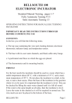
LIGHTING CONTROL CONSOLE
Manual
STAGE Software V 1.2
10
8
PRES
6
ET 1
4
2
0
FLASH
10
10
8
8
6
PRES
6
ET 2
2
2
CHA
SER
LEVE
L
4
LEVEL
10
ASSIG
N
2
0
8
FWD
0
0
REV
ADD
6
SOLO
CUE
P1
4
6
GRA
B
GRAB
1
GRAB
6
0
7
0
8
2
5
ETS
P2
10
4
3
H
2
PRES
6
2
FLAS
4
GO
10
8
4
8
9
11
12
2
10
2
10
RATE
6
4
4
10
8
8
0
6
CLEA
R
SAMP
LE
4
CLEA
R
SAMP
LE
2
0
1
©1993 Jands Electronics
This instruction manual and the software described in it are copyrighted,
with all rights reserved. Under the copyright laws, this manual or the
software may not be copied, in whole or part, without the written consent
of Jands Electronics.
10 September 1993
Technical Help and Support
If you have queries regarding the use of the STAGE or any other Jands
product, please contact us at:
Phone: +61 2 9582 0909
between 9:00am and 5:00pm Australian Eastern Standard Time
Fax:
+61 2 517 1045
Jands Electronics Pty Ltd
ACN 001 187 837
40 Kent Road Mascot
NSW 2020 AUSTRALIA
Internet: http://www.jands.com.au
2
3
Introduction
Stage 12/24 lighting control consoles are primarily designed to provide
the user with an economically priced unit of compact size offering
features and capabilities not available in similar units. These consoles are
also engineered to provide the user with the ability to expand the scope of
a lighting control system without the console becoming obsolete. This
important quality was provided by incorporating within Stage 12/24 units
DMX-512 digital outputs and other facilities usually only found in more
elaborate consoles.
The use of the USITT (1990) DMX-512 protocol, the communication
standard supported by all leading manufacturers of lighting equipment,
enables consoles and dimming systems to be linked together by means of
a common data path. This compatibility ensures that a lighting system
can be expanded without making the system infrastructure redundant.
1
Design Features
- 60 mm Presets arranged in 2 Preset format providing individual control
over channel levels.
- Channel Flash buttons to add or solo channel outputs regardless of the
current setting of the channel level fader.
- Add/Solo Master fader controlling the overall level of flash buttons.
- Add/Solo selector to determine the function of the flash buttons.
- Preset master faders providing control over each bank of Presets.
- Two independent Grab faders used to store scenes. These Grab faders
may also be considered as 3rd and 4th Presets.
- Master Flash buttons provided on Presets 1 and 2, Master faders, Chase
level master and Grab 1 and 2 faders.
- Chaser controls including Go/Cue, Speed, Direction and Level all of
which have the ability to chase through all or selected
channels in ascending or descending order.
- Audio trigger enabling the chase sequence to follow audio signal
- Wide Mode operation doubles the number of available control channels
which enables the Stage 12 console to operate as a single preset 24
Channel Console (48 single presets in the case of the Stage 24).
- DMX-512 output conforming with USITT DMX-512 (1990) Protocol
(AXR Output connector 5 pin Alcatel/Cannon).
- Stage 12/24 consoles may be used as slave consoles for the Jands
Event and ESP II consoles.
- Power input 12 V DC by means of a supplied plug-pak (Connector:
2.5mm co-axial).
2
Getting Started
Connecting Power
Plug the socket end of the plugpack output into the power receptacle
located on the rear face of the Stage 12/24 console. The plugpack
should be plugged into a mains outlet, and then the outlet switched on.
Please note that when power is removed from the console, all settings
are lost.
Connecting the Output of a Console to a Dimmer Rack
The DMX-512 control protocol output is standard on all Stage 12/24
consoles. Connect from the console's DMX output to the DMX input on
the dimmer rack, then check the dimmer instruction manual for details
on selecting DMX channels and looping the DMX line to other dimmer
racks.
Connecting the Audio Trigger Input
The Audio Trigger input is used to step the chase. Use a stereo plug
with balanced signals or a mono plug with unbalanced signals.
Input connector: 6.5mm jack; line level; 100 Hz trigger frequency
3
4
B. Channel Flash Buttons
A. Preset Faders
I. DIP Switch
AUDIO
TRIGGER
3
4
5
8
9
10
11
12
6
6
6
2
0
2
0
FLASH
4
4
7
6
6
6
8
8
GRAB 1
GRAB 2
RATE
6
8
10
0
2
4
6
8
10
CLEAR
SAMPLE
CLEAR
SAMPLE
E. Preset Masters
0
0
2
GRAB
LEVEL
4
P2
GO
CUE
REV
FWD
ASSIGN
LEVEL
CHASER
2
P1
PRESETS
SOLO
ADD
FLASH
MANUFACTURED BY JANDS ELECTRONICS (AUSTRALIA)
4
6
8
10
0
0
0
10
2
2
2
10
4
4
4
2
8
8
PRESET 2
10
10
PRESET 1
DMX
OUTPUT
H. DMX Output
8
(LINE, LEVEL)
(12V DC/500mA)
POWER
G. Power Input
10
OPTION
J. Audio Input
C. Grab Controls
F. Flash Controls
D. Chase Controls
Description of Major Parts
General Description of Major Parts
The front panel of the Stage 12/24 lighting control console is divided into
two main areas. The left section consists of the Preset Faders (A), and Flash
Buttons (B), which are used for both direct control and chase assigning. The
right section consists of all mastering controls including the Grab Controls
(C), Chase Controls (D), Preset masters 1and 2 (E), and Flash controls (F).
The rear panel of the Stage 12/24 houses all the input and output
connections for power, control signals, and the configuration DIP switch.
A Preset Faders are used to set up channel levels. The two Preset banks
are used to allow the operator to set up the next scene on one Preset
bank while the output from the other Preset bank is sent live to the stage.
B Flash Buttons (Channel) are used to momentarily flash on a channel to
the level of the Add/Solo Master. There is a flash button for each channel when the desk is operating in the normal 2 preset mode. If the console is set to Wide mode, only the first 12 channels have flash buttons
(24 channels in the case of the Stage 24).
C Grab Controls are used to store and playback two (2) independant
"snapshots" of the Stage 12/24 output.
D Chase Controls. There are five (5) controls in the Chase section:-
Level fader
Go/Cue button used to activate the chase output
Rate control fader
Fwd/Rev direction button
Assign button used in conjunction with the channel flash buttons to
select which channels will be included in the chase sequence
E P1 and P2 Masters. These two faders scale the level of the top (P1) and
bottom (P2) preset banks.
F Flash Master Controls. The Flash Master fader is used to set the level
of the flash buttons. The Add /Solo switch to the left of this fader sets
the method of operation for the flash buttons.
G Power Input consists of a 2.5 mm plugpack power receptacle for
connection to a suitably rated plugpack. See the appendix for plugpack
details.
5
H DMX Output. Control output for connection to a dimmer system or
other interfaces using the DMX-512 protocol.
I
DIP Switch allows the user to customise the operation of the console.
This is described in further detail on pages 10 and 11.
J
Audio Input allows the operator to automatically step the chaser in time
with the audio programme. Plugging a 6.5mm (1/4") plug into this
receptacle automatically forces the chaser to step in accordance with low
frequency peaks in the audio trigger signal.
Input connector: 6.5mm jack; line level; 100 Hz trigger frequency
6
Using Presets
Channel Preset Faders
There are two (2) rows of preset faders on the Stage 12/24. The top row of
faders is Preset 1 and the bottom row is Preset 2. These faders are used to
set lights to desired levels. The output level produced by the Preset faders is
dependent on the level of the P1 (or P2) Master fader.
Example:- Bring the P1 Master faders to 10 (100%).
- Move the Channel 1 Preset fader to 100% and you should see the lights
connected to that channel fade up to full level.
- Now fade up Channel 2 to 5 (50%) and check that the lights connected
to Channel 2 are at about 1/2 level.
- Finally fade the P1 Master down and Up to see how it scales the
Channel Preset faders.
Doubling Number of Channels
Using all Preset faders as a single preset to obtain double the number of
channels. (See Page 11) To double number of channels by using the console
in a single preset bank mode
Channel Flash Buttons
These buttons correspond to the Channel faders and perform two functions:
1
Flash. The buttons are used to momentarily flash on a channel. The type
of operation (add, solo) of the flash button depends on the setting of the
Add / Solo master switch. See page 8.
2
Chase Assign. Pressing the Asn button puts the Stage 12/24 into chase
assign mode, indicated by the LED in the Asn button being on. See Page
9.
7
Using Master Controls
P1 and P2 Master Faders
The P1 Master fader scales the top row of Preset faders. Likewise the P2
Master fader scales the overall level of the bottom row of Preset faders. By
moving the P1 fader up while moving the P2 fader down it is possible to
crossfade between the settings on the two rows of Preset faders.
Add/Solo Master Switch
All of the Flash buttons, including those associated with both channels,
Preset master, and Grab buttons, can be set to operate in two ways. To
change the operation of the flash buttons press the Add / Solo switch. With
each press of the button the LED within the switch will change to indicate
which mode has been selected.
•
Add - Indicated by the LED being OFF. Pressing a Flash button causes
that output to flash instantly to the level set by the Flash Master fader.
•
Solo - Indicated by the LED being ON. Pressing a Flash button causes
that output to flash instantly to the level set by the Flash Master fader,
while at the same time turning OFF all other desk outputs.
Add/Solo Fader
This fader scales the intensity of all flash buttons, including Preset and Grab
flash buttons.
While no dead blackout (DBO) facility is provided, the DBO effect can be
achieved by moving the Add/Solo fader to 0, setting the flash buttons to
Solo mode, and pressing any flash button.
8
Working with Grabs
The Stage 12/24 has two (2) fully independent Grab controls.
The Grab Controls:Grab Faders 1 and 2
These Level faders control the output level of the Grab scene
ranging from 0 to 100%.
Grab Flash Buttons 1 and 2
These buttons correspond to the Grab faders and act in a similar
way to Preset flash buttons, but will flash the Grab'd scene to the
Add/Solo level.
Grabbing a Scene
•
•
•
•
•
Decide which Grab fader is to be used to store the new scene.
If the Grab LED to the left of the Grab fader is on, press the button to
clear the fader.
Use the Preset faders, Flash buttons, Chaser, and the other Grab fader
outputs in any combination to generate the scene to be Grab'd.
Press the Grab button to store the current output.
The LED in the Grab button will illuminate to indicate there is a scene
stored in the Grab controls.
.
9
Working with Chases
The Stage 12/24 has the ability to chase through all or selected channels in
either ascending or descending order.
The Chase Controls:The chase controls are used to set the speed, direction, level of the Chase
output, assign channels to the chase, and enable the output.
Rate Fader
The Rate fader can be used to speed up or slow down a Chase.
Pushing it to zero will slow the chase to a STOP; pushing it to full
will increase the speed to the maximum speed of 1000 beats per
minute.
Please note that the chase is automatically stepped from the audio
signal when a plug is inserted in the Audio Trigger input on the back
panel.
Chase Direction
The Direction button is used to set the direction of the Chase. Push the
button to change the setting. With each press of the button the
direction changes from either forward (ascending, LED off) to
reverse (descending, LED on).
Assign Button
The Assign button is used to change the console from normal to chase
assign mode. When in chase assign mode (Asn LED on), the channel
mimic LEDs show which channels are currently assigned to the
chase; pressing a channel flash button alternately adds or deletes a
channel from the chaser.
Please note that when the console is first turned on, all channels are
automatically assigned to the chaser.
Go/Cue Button
The operation of the Go/Cue button is changed by the position of
configuration DIP switch 3 accessible from the back panel. However,
in either mode when the Go/Cue button is pressed, the Chase is reset
to the lowest step if forward mode is selected or the highest step if
reverse mode is selected.
10
When DIP switch #3 is off, pressing the Go/Cue button alternately activates/
deactivates the Chase. When the chaser is not active, the LED in the switch
flashes at the chase step rate; when the chaser is active, the LED is on
continuously.
When DIP switch #3 is on, the chase is always active at the level of the
chase level fader. Additionally, the Go/Cue button is used as a chase flash
button, flashing the chase to the level of the Add/Solo fader when the button
is pressed. As with all other flash buttons, if the console is in Solo mode all
other output is removed when the chase Go/Cue button is pressed.
11
Configuring the Console
A 4 way DIP switch accessible through the rear panel enables the user to
change some of the operating parameters of the console. These are as
follows:#1
Use the STAGE as a slave console to an Event or ESP II
master console.
#2
Reverse the operation of the P2 master fader such that it is at
full when it is at the 0 position. This is used to enable single
action crossfades.
#3
Change the operation of the chase. See page 10.
#4
Single preset wide mode. The console operates as a single
preset console, with flash buttons on the first 24 channels.
(12 for Stage 12)
To change the console configuration, remove console power, change
switch positions as desired, and reapply power. Changes will be active
immediately.
Please note that when DIP switch #1 is on, all other switches are ignored.
When DIP switch #4 is on, DIP switch #2 is ignored.
12
Appendix 1 - Pin Assignments
DMX Digital
Output Socket
PIN No
Signal
1
2
3
4
5
SHIELD
SIGNAL SIGNAL +
NOT USED
NOT USED
Connector type: Cannon 5 pin AXR
USITT DMX-512(1990) Protocol
Desk Link Cable
To slave a STAGE console to expand an Event, Event Plus, or
ESP II console connect a cable wired as detailed below between
the DMX output of the STAGE to the MIDI input on the Event,
Event Plus, or ESP II console. Set DIP switch #1 on and apply
power to the STAGE console. Configure the Master console as
per the user manual. It is not possible to link two STAGE
consoles together.
Cannon 5 Pin
Din 5 Pin
PIN No
PIN No
2
390R 1/4w 5% 4
3
5
Power
Voltage
Consumption
Connector
12 volts DC, floating output
6 watts (9 watts 24 channel)
2.5mm co-axial plugpak connector
The STAGE consoles accept standard 12 volt DC plugpacks,
rated at 0.5A for 12 channels and 0.75A for 24 channel
consoles. Plug tip positive. Do not use the plugpack to power
other equipment at the same time.
Audio Trigger
Connector
Level
Trigger Frequency
6.5mm (1/4") Jack
line voltage
Approx 100Hz
Use a stereo connector for a balanced input signal, or a mono
connector for a single ended signal. Connector insertion automatically sets the chase trigger source to the Audio signal
source.
13
Table of Contents
Introduction.........................................................................................1
Design Features...................................................................................2
Getting Started....................................................................................3
Description of Major Parts.................................................................5
Using Presets..................................................................................7
Using the Master Controls.............................................................8
Working with Grabs..........................................................................9
Working with Chases ......................................................................10
Configuring the Console..................................................................12
Appendix .........................................................................................13
14