1
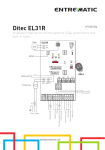
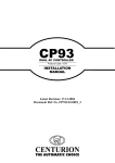
USER’S MANUAL MIG ____________________________________________________________________ SLIDING GATE OPERATORS INSTALLATION MANUAL CE ____________________________________________________________________________________ MATT di LIEVORE SRL Via Bianche 7 36010 Carre’ ( VI ) Tel. 0445 / 892223 Fax 0445 / 390346 USER’S MANUAL MIG ____________________________________________________________________ GENERAL SAFETY If correctly installed and used, this automation device satisfies the required safety level standards.However, it is advisable to observe some practical rules in order to avoid accidental problems. Before using the automation device, carefully read the operation instructions and keep them for future reference. Keep children, people and things outside the automation working area, particularly during its operation. Keep radio control or other control devices out of children’s reach, in order to avoid any unintentional automation activation. Do not intentionally oppose the leaf movement. Do not modify the automation components. In case of malfunction, disconnect the power supply, activate the emergency release to have access to the automation and request the assistance of a qualified technician (installer). Before proceeding to any outside cleaning operation, disconnect the power supply. Keep the photocell optical components and light signal devices clean. Check that the safety devices (photocells) are not obscured by branches or shrubs. For any direct assistance to the automation system, request the help of a qualified technician (installer). Have qualified personnel check the automation system once a year. Manual release activation could cause the door to be subject to uncontrolled movements in the case where any mechanical faults are present or the door is not balanced. Inspect the installation frequently if it shows any unbalance or signs of mechanical damage to cables and supports”. Do not use the operator if it needs to be repaired. Keep the instructions together with the technical brochure for future reference. This product was exclusively designed and manufactured for the use specified in the present documentation. Any other use not specified in this documentation could damage the product and be dangerous. The Company declines all responsibility for any consequences resulting from improper use of the product, or use which is different from that expected and specified in the present documentation. Do not install the product in explosive atmosphere. The construction components of this product must comply with the following European Directives: 2004/108/CEE, 2006/95/EEC, 98/37/EEC and subsequent amendments. As for all non-EEC countries, the above-mentioned standards as well as the current national standards should be respected in order to achieve a good safety level. The Company declines all responsibility for any consequences resulting from failure to observe Good Technical Practice when constructing closing structures (door, gates etc.), as well as from any deformation which might occur during use. The installation must comply with the provisions set out by the following European Directives: 2004/108/CEE, 2006/95/EEC, 98/37/EEC and subsequent amendments. Disconnect the electrical power supply before carrying out any work on the installation. Also disconnect any buffer batteries, if fitted. ____________________________________________________________________________________ MATT di LIEVORE SRL Via Bianche 7 36010 Carre’ ( VI ) Tel. 0445 / 892223 Fax 0445 / 390346 USER’S MANUAL MIG ____________________________________________________________________ Fit an omnipolar or magneto thermal switch on the mains power supply, having a contact opening distance equal to or greater than 3,5 mm. Check that a differential switch with a 0.03A threshold is fitted just before the power supply mains. Check that earthing is carried out correctly: connect all metal parts for closure (doors, gates etc.) and all system components provided with an earth terminal. Fit all the safety devices (photocells, electric edges etc.) which are needed to protect the area from any danger caused by squashing, conveying and shearing. Position at least one luminous signal indication device (blinker) where it can be easily seen, and fix a Warning sign to the structure. The Company declines all responsibility with respect to the automation safety and correct operation when other manufacturers’ components are used. Only use original parts for any maintenance or repair operation. Do not modify the automation components, unless explicitly authorized by the company. Instruct the product user about the control systems provided and the manual opening operation in case of emergency. Do not allow persons or children to remain in the automation operation area. Keep radio control or other control devices out of children’s reach, in order to avoid unintentional automation activation. The user must avoid any attempt to carry out work or repair on the automation system, and always request the assistance of qualified personnel. Check that the stated temperature range is compatible with the place where the operator is to be installed. If present, the hold button (hold-to-run control) must be fitted within sight of the door but away from the moving parts, at a height of 1.5 m, and must not be accessible to the public. If the operator is fitted at a height lower than 2.5 m, you must guarantee an adequate degree of protection for the electrical and mechanical parts. Make sure that squashing is avoided between the moving parts and surrounding fixed parts. Fit all the safety devices (photocells, safety edges etc.) required to protect the area from any danger of squashing, drawing in and shearing. After completing the installation, ensure that the motor is set correctly and that the protection and release systems operate correctly. Anything which is not expressly provided for in the present instructions is not allowed. ____________________________________________________________________________________ MATT di LIEVORE SRL Via Bianche 7 36010 Carre’ ( VI ) Tel. 0445 / 892223 Fax 0445 / 390346 USER’S MANUAL MIG ____________________________________________________________________ 1. GENERAL OUTLINE Electromechanical operator designed to automate residential-type gates. The operator keeps the gate blocked on closing and on opening, without needing an electric lock. The operator has no mechanical clutch. It must be controlled by an electronic control panel provided with torque setting. The end-of-stroke operation is managed by the control panel. GROUND is a series of powerful and silent gearboxes made for the automatic movement of the winged gates and doors up to 3 meters for the leaf. GROUND OIL and GROUND 24 V version, prepared for intensive use, are an ideal choice for condo applications. 2. INSTALATION Preliminary checks Check that: • The gate structure is sufficiently sturdy. • Also make sure that the actuator pushes against the leaf reinforced section. • The leaves move manually and without effort all along their stroke. • The door stop plates are fitted at the end of both closing and opening strokes. • If the gate has not been recently installed, check the wear condition of all components. • Repair or replace faulty or worn parts. - moto-riduttore una piazzola in cemento. Power supply cable The board power supply cable must be of the H 05 RN-F type or equivalent. The equivalent cable must guarantee: - permanent outside use - rated voltage of 300/500 V ____________________________________________________________________________________ MATT di LIEVORE SRL Via Bianche 7 36010 Carre’ ( VI ) Tel. 0445 / 892223 Fax 0445 / 390346 USER’S MANUAL MIG ____________________________________________________________________ - maximum temperature on the cable surface of +50° C - minimum temperature of -25° C Moreover, it must have a minimum section of 3 x 1.5 mm2 and, for the cable to hold correctly, it must be provided with an external sheath of Ø = 7.1 to 9.6 mm. The wiring of the terminal board must be carried out as shown in Fig. 3 M1= operation 1 M2= operation 2 T= earthing N = common WARNING! When the power supply cable is damaged, it must be replaced by the manufacturer or its technical assistance service, or else by a person having similar qualification, in order to prevent any risk. External meausures ____________________________________________________________________________________ MATT di LIEVORE SRL Via Bianche 7 36010 Carre’ ( VI ) Tel. 0445 / 892223 Fax 0445 / 390346 USER’S MANUAL MIG ____________________________________________________________________ 3. POSITIONING FOR BASE PLATE prepare the sub structure in order to fix base plate, respecting approximately measures like Fig. 2 4. POSITIONING OF GEAR MOTOR Position the gear motors (Fig. 3) on the great plate (A), using the appropriate screws supplied. The right coupling between rack and pinion may be carried out by registering of fixing the small plates (B) to the great, through the eyelets associated. unlock the gear motors, through appropriate release lever (Fig. 4). For the following positioning and attaching the rack. ____________________________________________________________________________________ MATT di LIEVORE SRL Via Bianche 7 36010 Carre’ ( VI ) Tel. 0445 / 892223 Fax 0445 / 390346 USER’S MANUAL MIG ____________________________________________________________________ 5. FIXING RACK AND END-RUN DEVICE 6. THE ELECTRICAL PLANT SET-UP Position the first element of rack on the cogwheel, previously unlocked, as in Fig. 5. Following fix the element to the gate, in the way you wish, by applying to it the other elements of rack necessary, ensure that all be united and aligned. Locate the desired position and fix end-run device (F) on Rack as indicated in the previous Fig. 2, those with grains included. Close the release lever and perform the necessary electrical connections. Fig.6 Lay out the electrical installation fig. 6 with reference in force for electrical installation. The mains power supply connections must be kept totally separate from the service connections (photocells, electric edges, control devices etc.). ____________________________________________________________________________________ MATT di LIEVORE SRL Via Bianche 7 36010 Carre’ ( VI ) Tel. 0445 / 892223 Fax 0445 / 390346 USER’S MANUAL MIG ____________________________________________________________________ Connect the control and safety devices in compliance with the previously mentioned electrical installation standards. The main automation components are: Control panel and incorporated receiver Key selector Blinker tuned in with antenna Operator Pair of outside photocells Pair of inside photocells 1-2-4 channel transmitter Antenna cable Warning! For actuator wiring and accessory connection, refer to the relevant instruction manuals. The control panels and accessories must be suitable for use and conform to current standards. Should the opening or closing direction be incorrect, it is possible to invert the connections of operation 1 and operation 2 on the control board. The first command after an interruption of the power supply should be an opening maneuver. 7. CHECKING THE AUTOMATION Before considering the automation completely operational, the following checks must be made with great care: • Check that all the components are firmly anchored. • Control all the safeties work properly (i.e. photocells, pneumatic skirt, etc.). • Check the emergency maneuvers control. • Check the opening and closing maneuvers using the controls. • Check the control unit’s electronic logic in normal (or customized) operation. 8. USE OF THE AUTOMATION Since the automation may be remote controlled either by radio or a Start button, it is essential that all safeties are checked frequently. ____________________________________________________________________________________ MATT di LIEVORE SRL Via Bianche 7 36010 Carre’ ( VI ) Tel. 0445 / 892223 Fax 0445 / 390346 USER’S MANUAL MIG ____________________________________________________________________ Any malfunction should be corrected immediately by a qualified specialist. Keep children at a safe distance from the field of action of the automation. 9. THE CONTROLS With the automation the gate has a power driven opening and closing. The controls can come in various forms (i.e. manual, remote controlled, limited access by magnetic badge, etc.) depending on needs and installation characteristics. For details on the various command systems, consult the specific instruction booklets. Anyone using the automation must be instructed in its operation and controls. 10. MAINTENANCE When carrying out maintenance operation on the controller, disconnect it from the mains power supply. The actuator does not require periodical maintenance operations. • Check the safety devices of the gate and automation. • Periodically check the pushing force and correct the value of the electric torque in the control board if necessary. • In case of unsolved operation failures, disconnect the unit from the mains power supply and ask for the intervention of qualified personnel (installer). When the unit is out of order, activate the manual release to perform manual opening and closing maneuvers. 11. NOISE The aerial noise produced by the gear motor under normal operating conditions is constant and does not exceed 70dB (A). 12. TROUBLES AND SOLUTIONS Incorrect operation of gear-motor ____________________________________________________________________________________ MATT di LIEVORE SRL Via Bianche 7 36010 Carre’ ( VI ) Tel. 0445 / 892223 Fax 0445 / 390346 USER’S MANUAL MIG ____________________________________________________________________ Check for the presence of power supply to the gear motor using a suitable instrument after opening or closing commands have been given. If the motor vibrates but does not turn, the causes could be the following: a) incorrect connection of the C common wire. b) operation capacitor not connected to the terminals on the control board. c) if the moving direction of the leaf is opposite to the right one, invert the motor running connections. Incorrect operation of the electrical accessories All control and safety devices can cause, in case of failure, malfunctioning or stoppage of the automation. To identify the failure, it is advised to disconnect all the devices of the automation one by one until the one causing the problem is found. After fixing or replacing the defective device, reset all the devices previously disconnected. Refer to the relevant instruction manual for all the devices installed on the automation. 13. MANUAL MODE In case of interruption of the power supply, failure, or need activities on the plant, is possible to operate the gate in manual mode, as shown in Fig. 4. Insert the key in lock release lever and rotate in order to open it. Pull off the lever up to a corner ____________________________________________________________________________________ MATT di LIEVORE SRL Via Bianche 7 36010 Carre’ ( VI ) Tel. 0445 / 892223 Fax 0445 / 390346 USER’S MANUAL MIG ____________________________________________________________________ over 90° and make the manoeuvres you like. At the end of the operations, restore the lever in the starting position. 14. CARATTERISTICHE Supply Engine supply Engine power Max weight Max thrust Thermal protection Temperature range Cycle Weight (Vac 50Hz) (Vac/Vdc) (W) (kg) (Nm) (°C) (%) (Kg) MIG 400 MIG 600 MIG 1000 230 24/220 70/300 400 300 -/integrated -25 / +70 90/40 9 230 220 400 600 690 integrated -25 / +70 50 9,5 230 220 500 1000 870 integrated -25 / +70 50 10 ____________________________________________________________________________________ MATT di LIEVORE SRL Via Bianche 7 36010 Carre’ ( VI ) Tel. 0445 / 892223 Fax 0445 / 390346 USER’S MANUAL MIG ____________________________________________________________________ 11. ELECTRONIC EQUIPMENT L1 (220V) INTRODUCTION The electronic equipment Type S1R can be used to control one actuator for a sliding gate. The max. absorption of the device is 600W per 230V 50Hz. The set-up of the parameters must be carried out after the installation of all the equipment. DESCRIPTION TR1 – TR4 DSW1 DL1-DL8 F1 F2 M1 M2 CN2 K1-K3 TF1 U1 JR1 = = = = = = = = = = = = Trimmers Dip switches LED Line 230V fuse Low voltage fuse Signal terminal board Power terminal board Antenna terminal board Relais Transformer Microprocessor Reset jumper ____________________________________________________________________________________ MATT di LIEVORE SRL Via Bianche 7 36010 Carre’ ( VI ) Tel. 0445 / 892223 Fax 0445 / 390346 USER’S MANUAL MIG ____________________________________________________________________ INSTALLATION Before making the electrical connections it is necessary to turn off the mains of 230V 50Hz and regulate the motor torque to a minimum. Use 0.5mm2 wires to make connections to the pushbuttons, photocells and 24V power supply. For connections to the electric lock, flasher and motors it is necessary to use at least 1.5mm2 wires. Use wires of at least 2,5mm2 to make connections to supply mains of 230V 50Hz. ____________________________________________________________________________________ MATT di LIEVORE SRL Via Bianche 7 36010 Carre’ ( VI ) Tel. 0445 / 892223 Fax 0445 / 390346 USER’S MANUAL MIG ____________________________________________________________________ M1 terminal board START STOP ST.P PHOTO SAFETY L.S.C. L.S.O. COM + 24V - 24V W.LIGHT = = = = = = = = = = = Normally open pushbutton (opening / closing) Normally closed pushbutton (stop) Normally open pushbutton (pedestrian opening) Normally closed input external photocell Normally closed safety contact Normally closed contact limit switch closing Normally closed contact limit switch opening Common for inputs and warning light Positive supply accessories 24V CC Negative supply accessories 24V CC Warning light 24V 3W max M2 terminal board L N FLASH COM C O = = = = = = Input 230V 50Hz Line Input 230V 50Hz Neutral (Flash light common contact) Flash light 230V 50Hz 15W max Motor common coils Motor closing windings Motor opening windings It is necessary to connect a capacitor between C and O terminals. It is necessary to clamp the cables of the M1-signals terminal board to M2-power terminal separately. Fit a jumper cable on the normally-closed contacts when they are not in use. If one of the normally-open inputs (START and STOP) is closed, or one of the normallyclosed inputs is open, the TEST LED flashes at high frequency. In this case it is not possible to carry out the learning strokes procedure. ____________________________________________________________________________________ MATT di LIEVORE SRL Via Bianche 7 36010 Carre’ ( VI ) Tel. 0445 / 892223 Fax 0445 / 390346 USER’S MANUAL MIG ____________________________________________________________________ OPERATING MODES CONDOMINIUM AUTOMATIC: The gate is opened when the START button is pressed whether the gate is closed or being closed. The START command is ignored while the gate is being opened, whereas during the pause phase it makes the timing of this phase restart. After pressing STOP, pressing START closes the gate. SUPERAUTOMATIC: The gate is opened when the START button is pressed whether the gate is closed or being closed. While the gate is being opened however it produces a STOP, after which a subsequent START closes the gate. During the pause phase, pressing the START button closes the gate. After pressing STOP, pressing START closes the gate. AUTOMATIC: The gate is opened when the START button is pressed whether the gate is closed or being closed. The START command is ignored while the gate is being opened, whereas during the pause phase it makes the gate close again. After pressing STOP, pressing START closes the gate. SEMIAUTOMATIC: The START button controls the opening, closing and halting of the gate. After it is opened, it is necessary to press the START button to close it again. While the gate is being opened, pressing START halts the gate and another pulse makes the gate close. If START is pressed during the closing phase the direction is inverted. After pressing STOP, pressing START closes the gate. STEP BY STEP: The gate is opened when START pulse is pressed while the gate is closed. The START command produces a STOP during the opening phase, subsequently pressing START causes the gate to close, and pressing START again produces a STOP. After pressing STOP, pressing START closes the gate. MAINTENANCE ____________________________________________________________________________________ MATT di LIEVORE SRL Via Bianche 7 36010 Carre’ ( VI ) Tel. 0445 / 892223 Fax 0445 / 390346 USER’S MANUAL MIG ____________________________________________________________________ There are two 5x20-size fuses on the board that protect the 230V line and the secondary of the transformer. The fuses have the following values: 230V line F1 = 5 A fast Secondary F2 = 630 mA fast Before replacing the fuses it is necessary to turn off the 230V mains power supply. The power of these fuses must not be modified. There is no other component on the board that can be repaired or replaced by the installation personnel. For any other intervention it is necessary to contact technical support. SETTINGS DIP 1 OFF OFF OFF OFF ON ON ON ON DIP 4 5 6 DIP 7 OFF DIP 2 OFF OFF ON ON ON ON OFF OFF DIP 3 OFF ON OFF ON OFF ON OFF ON Operating mode Condominium automatic Condominium automatic + Comfort (*) Superautomatic Superautomatic + Comfort (*) Automatic Automatic + Comfort (*) Semiautomatic Step by step Function Preflashing Flash light type Photocell retrigger(***) DIP 8 OFF ON Enabled With board Enabled (**) OFF Disabled Lamp only Disabled (**) Installation type SLIDING GATES (*) The function comfort enables the gate to be closed 5 seconds after the photocells have received a pulse, regardless of the timing of the pause setting. ____________________________________________________________________________________ MATT di LIEVORE SRL Via Bianche 7 36010 Carre’ ( VI ) Tel. 0445 / 892223 Fax 0445 / 390346 USER’S MANUAL MIG ____________________________________________________________________ (**) If comfort is enabled dip 6 don't cares (***) The function photocell retrigger makes the timing of the pause restart if the photocells are in use during the pause itself. After each mode change it is necessary to short circuit JR1 reset contacts for a few seconds so that the change can take effect) REGULATIONS Trimmer (TR1) DELAY (TR2)TORQUE (TR3) SK - CU (TR4) BRAKE Function Pause time Motor torque Slowing speed Brake intensity Range From 0 to 140 secondi From 20 to 100% From 0 to 100% From 0 to100% The TR1 DELAY trimmer regulates the timing of the pause (the time the gate remains still before being closed automatically), which varies from 1 to 120 seconds. The TR2 TORQUE trimmer regulates the torque of the motor. For motors equipped with a clutch or for oil-pressure motors it is necessary to rotate the TR2 TORQUE trimmer to the maximum extent possible (i.e., a complete clockwise rotation). The TR3 SK-CU trimmer regulates the speed at which the timing is slowed, which can be regulated within the safety parameters. By regulating the TR3 SLACK trimmer to the maximum extent possible (i.e., a complete clockwise rotation), the slowing does not take place (see learning procedure without slowing). The TR4 BRAKE trimmer regulates the brake intensity. To disable the brake it is necessary to regulate the trimmer to a minimum. ____________________________________________________________________________________ MATT di LIEVORE SRL Via Bianche 7 36010 Carre’ ( VI ) Tel. 0445 / 892223 Fax 0445 / 390346 USER’S MANUAL MIG ____________________________________________________________________ REMOTE CONTROLS LEARNING The SR equipment is equipped with a built-in decoder able to memorize up to 128 rolling-code remote controls or one fixed-code remote controls. Start function In closed-gate mode, press the PROG.B button and hold it down until the TEST LED starts to flash. Release the PROG.B button. Within 10 seconds, set the remote control button that you want to connect to the START command. The completion of the process will be indicated by the simultaneous flash of the TEST LED, of the flasher and of the pilot lamp, followed by the termination of the flashing of the TEST led. With rolling code remote controls, repeat the process for each remote control to be set. With fixed-code remote controls it is sufficient to carry out the process for only one model. Pedestrian start function In closed-gate mode, press the PROG.B button and hold it pressed until the TEST led starts to flash; don’t release the button and wait until the flashing speeds up. Release the PROG.B button. Within 10 seconds set the button of the remote control to learn and to be connected with the PEDESTRIAN START control. When the learning has been carried out it will be indicated by the simultaneous flash of the TEST led, flasher and of the pilot lamp, followed by the termination of the flashing of the TEST led. In case of rolling code-type remote controls repeat the operation for each remote control to learn. In case of fixed-type remote controls it is sufficient to carry out the learning of one single model. Complete erasing of the learnt remote controls In closed-gate mode, press the PROG.B button and hold it pressed till when the TEST led starts to flash; don’t release the button and wait until the flash gets quicker; don’t release the button and wait until the flash gets very quick; don’t release the button. When the blanking /blackout of ALL the learned remote controls has been carried out it will be indicated by the simultaneous flash of the TEST led, flasher and of the pilot lamp, followed by the termination of the flashing of the TEST led. ____________________________________________________________________________________ MATT di LIEVORE SRL Via Bianche 7 36010 Carre’ ( VI ) Tel. 0445 / 892223 Fax 0445 / 390346 USER’S MANUAL MIG ____________________________________________________________________ INSTALLATION SLIDING GATE TYPE TRIMMER • • • • Trimmer Trimmer Trimmer Trimmer TR1 TR2 TR3 TR4 DELAY as you need. TORQUE to the minimum. SK-CU as you need. BRAKE as you need. DIP SWITCH From 1 to 6 as you need. • dip switch 7 = OFF and dip switch 8= OFF Press the PROG.A learning button for at least 3 seconds, until the TEST LED starts to flash, then do as follows. Learning ends when the TEST LED turns off. ____________________________________________________________________________________ MATT di LIEVORE SRL Via Bianche 7 36010 Carre’ ( VI ) Tel. 0445 / 892223 Fax 0445 / 390346 USER’S MANUAL MIG ____________________________________________________________________ CONNECTIONS ____________________________________________________________________________________ MATT di LIEVORE SRL Via Bianche 7 36010 Carre’ ( VI ) Tel. 0445 / 892223 Fax 0445 / 390346 USER’S MANUAL MIG ____________________________________________________________________ 15. ELECTRONIC EQUIPMENT L1LW (24V) Firmware versione 1.02 JEXP1 ____________________________________________________________________________________ MATT di LIEVORE SRL Via Bianche 7 36010 Carre’ ( VI ) Tel. 0445 / 892223 Fax 0445 / 390346 USER’S MANUAL MIG ____________________________________________________________________ SETTINGS DIP 7 OFF DIP 1 2 3 4 5 8 JEXP1 DIP 6 OFF Operating mode SLIDING GATE Function Preflashing 3 SECONDS Condominium automatic Automatic closing Stop function ON Enabled Enabled Enabled Photocell open Closing after photocell action Enabled Safety mode Always on o Out K OPT 2 canale radiocomando OFF Disabled Disabled Disabled Emergency button Disabled Only opening Pedestrian passage TRIMMER SET Trimmer TR1 - TR OPEN TR2 - TR CLOSE TR3 - SP SLK TR4 - DELAY TR5 - BR / TRSLK Function Opening power Closing power Slowing speed Pause time Regulation Slowing speed from 2 to 120 secondi ____________________________________________________________________________________ MATT di LIEVORE SRL Via Bianche 7 36010 Carre’ ( VI ) Tel. 0445 / 892223 Fax 0445 / 390346 USER’S MANUAL MIG ____________________________________________________________________ REMOTE CONTROLS LEARNING The SR equipment is equipped with a built-in decoder able to memorize up to 128 rolling-code remote controls or one fixed-code remote controls. Start function In closed-gate mode, press the P2 button and hold it down until the TEST LED starts to flash. Release the P2 button. Within 10 seconds, set the remote control button that you want to connect to the START command. The completion of the process will be indicated by the simultaneous flash of the TEST LED, of the flasher and of the pilot lamp, followed by the termination of the flashing of the TEST led. With rolling code remote controls, repeat the process for each remote control to be set. With fixed-code remote controls it is sufficient to carry out the process for only one model. Pedestrian start function In closed-gate mode, press the P2 button and hold it pressed until the TEST led starts to flash; don’t release the button and wait until the flashing speeds up. Release the P2 button. Within 10 seconds set the button of the remote control to learn and to be connected with the PEDESTRIAN START control. When the learning has been carried out it will be indicated by the simultaneous flash of the TEST led, flasher and of the pilot lamp, followed by the termination of the flashing of the TEST led. In case of rolling code-type remote controls repeat the operation for each remote control to learn. In case of fixed-type remote controls it is sufficient to carry out the learning of one single model. Complete erasing of all learnt remote controls In closed-gate mode, press the P2 button and hold it pressed till when the TEST led starts to flash; don’t release the button and wait until the flash gets quicker; don’t release the button and wait until the flash gets very quick; don’t release the button. When the blanking /blackout of ALL the learned remote controls has been carried out it will be indicated by the simultaneous flash of the TEST led, flasher and of the pilot lamp, followed by the ending of the flashing of the TEST led. ____________________________________________________________________________________ MATT di LIEVORE SRL Via Bianche 7 36010 Carre’ ( VI ) Tel. 0445 / 892223 Fax 0445 / 390346 USER’S MANUAL MIG ____________________________________________________________________ Erasing of one learnt remote controls In closed-gate mode, press the P2 button and hold it pressed till when the TEST led starts to flash; don’t release the button and wait until the flash gets quicker; don’t release the button and wait until the flash gets very quick; release the button and push the start button on the remote controller that you want to erase by the ending of the flashing of the TEST led you erased the remote controller. LEARNING WARNING the GATE has to be closed Press the P1 learning button for at least 3 seconds, until the TEST LED starts to flash, then do as follows: WARNING If do not start with learning until 10 sec DL4 LED turns off and learning is not done correctly, so you have to restart. During the learning you have to pay attention on photocells and do not press STOP button, otherwise you have to restart learning. 1° input START: the gate begins to open at standard speed 2° input START: When you decide to start the slow-stroke phase, press START: the slowstroke phase starts After 3 seconds boom starts closing. the boom begins to close at standard speed ____________________________________________________________________________________ MATT di LIEVORE SRL Via Bianche 7 36010 Carre’ ( VI ) Tel. 0445 / 892223 Fax 0445 / 390346 USER’S MANUAL MIG ____________________________________________________________________ 3° input START: When you decide to start the slow-stroke phase, press START: the slowstroke phase starts until the limit switch After 3 seconds gate starts opening. 4° input START: gate stops at pedestrian point decided. After 3 seconds gate starts closing. Wait until the DL4 LED turns off. Learning finished. The subsequent maneuver will be standard within the parameters just set If one of the normally-open inputs (START, CL/SP, OPEN) is closed, or one of the normally-closed inputs (STOP, PHOTO, SAFETY) is open, the TEST LED flashes at high frequency. In this case it is not possible to carry out the learning strokes procedure. Fit a jumper cable on the normally-closed contacts when they are not in use. ____________________________________________________________________________________ MATT di LIEVORE SRL Via Bianche 7 36010 Carre’ ( VI ) Tel. 0445 / 892223 Fax 0445 / 390346 USER’S MANUAL MIG ____________________________________________________________________ CONNECTION M1 1 OPEN 2 START 3 CL/SP Opening if boom is down, or if boom is closing Opening if boom is down, stop during opening if DIP 2 OFF, closing if boom is stopped, opening if boom is closing Pedestrian passage with boom down, closing if boom is open If DIP 4 OFF stop any boom action, if activated no action 4 STOP/EM 5 PHOTO If DIP 4 ON stops any boom action, boom remains closed until command is activated than star opening. Opening if boom closing, if active no action. If DIP 8 OFF change direction if boom closing, if active no action. If DIP 8 ON Se DIP 8 ON: OFF change direction if boom closing or opening, if active no. 6 SAFETY 7 COM 8 L.S.C. 9 L.S.O. 10 COM Common for inputs 11 K OPT Fast flashing during closing slow flashing during opening, light on if boom is open, light off if boom closed. 12 K OPT supply accessories 24V CC (picture down) 13 + V 24 V Positive supply accessories 24V CC 14 - V 24 V Negative supply accessories 24V CC Common for inputs Normally closed contact limit switch closing Normally closed contact limit switch opening. ____________________________________________________________________________________ MATT di LIEVORE SRL Via Bianche 7 36010 Carre’ ( VI ) Tel. 0445 / 892223 Fax 0445 / 390346 USER’S MANUAL MIG ____________________________________________________________________ CONNECTION M4 1 + LOCK OR LBC 2 - LOCK OR LBC 3 + FLASH 4 - FLASH 5 + M1 6 - M1 Active during opening/closing, fixed if boom stopped Flashing during opening/closing, if DIP 1 ON preflashing, 3 sec before any action Motor CONNECTION M3 1 GND 2 + ANTENNA 1 S1 Sec 1 trasformatore 22 V 2 0 com trasformatore 0 V 3 S2 Sec 2 trasformatore 22 V antena CONNECTION CN2 ____________________________________________________________________________________ MATT di LIEVORE SRL Via Bianche 7 36010 Carre’ ( VI ) Tel. 0445 / 892223 Fax 0445 / 390346 USER’S MANUAL MIG ____________________________________________________________________ WARNINGS Correct controller operation is only ensured when the data contained in the present manual are observed. The Company is not to be held responsible for any damage resulting from failure to observe the installation standards and the instructions contained in the present manual. The descriptions and illustrations contained in the present manual are not binding. The Company reserves the right to make any alterations deemed appropriate for the technical, manufacturing and commercial improvement of the product, while leaving the essential product features unchanged, at any time and without undertaking to update the present. Dichiarazione CE di conformità Con la presente dichiariamo che il prodotto RED 2-4-6 è conforme alla direttiva sulla compatibilità elettromagnetica (89/336/CCE, 93/68/CEE). Norme applicate in particolare: EN 55022, EN 61000-3-2, EN 61000-3-3, EN 50082-1 Norme nazionali applicate: UNI 8612 Lievore srl ____________________________________________________________________________________ MATT di LIEVORE SRL Via Bianche 7 36010 Carre’ ( VI ) Tel. 0445 / 892223 Fax 0445 / 390346