1
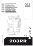
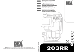
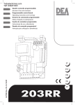
Quadro comando programmabile
Istruzioni d’uso ed avvertenze
Programmable control board
Operating instructions and warnings
Armoire de commande programmable
Notice d’emploi et avertissements
Cuadro de maniobra programable
Instrucciones de uso y advertencias
Quadro de comando programável
I67700X Rev. 07- 10/07/08
Instruções para utilização e advertências
203RR
R
UTILIZZO DEL LIBRETTO
Per facilitare la comunicazione e la rintracciabilità di particolari importanti informazioni all’interno del testo DEA System adotta
la simbologia riportata.
USE OF THIS BOOKLET
In order to facilitate communication and the traceability of
particularly important parts of the text, DEA System adopts the
symbols provided.
UTILISATION DE CE LIVRET
Pour faciliter la communication et le repérage de renseignements spéciaux et importants à l’intérieur du texte, DEA System a
adopté la symbologie indiquée.
UTILIZACIÓN DEL MANUAL
Para facilitar la comunicación y la trazabilidad de informaciones de particular importancia, DEA System adopta, en el interior
del texto, la simbología reproducida.
UTILIZAÇÃO DO FOLHETO
Para facilitar a comunicação e localizar pormenores importantes de informações no interior do texto, a DEA System adoptou
os símbolos apresentados.
Avvertimento
Warning
Avertissement
Advertencia
Advertência
Pericolo
Danger
Danger
Peligro
Perigo
Consultazione
Consultation
Consultation
Consultación
Consulta
Osservazione
Observation
Observation
Observación
Observação
Ispezione
Inspection
Inspection
Inspección
Inspecção
Certificazione
Certification
Certification
Certificación
Certificado
Operating instructions and warnings
203RR
Control board 230V for gate operators
Instructions and warnings
ENGLISH
INDEX
OVERVIEW ................................................................................................................................13
1 PRODUCT CONFORMITY .....................................................................................................13
2 WARNINGS ..........................................................................................................................13
3 MODELS AND CONTENTS OF THE PACKAGE .......................................................................14
4 PRODUCT DESCRIPTION ......................................................................................................14
5 TECHNICAL DATA.................................................................................................................15
6 OPERATING CONDITIONS ...................................................................................................15
7 ASSEMBLY AND WIRING INSTRUCTIONS ..............................................................................15
8 USE INSTRUCTIONS .............................................................................................................16
8.1 Visualization of inputs status .......................................................................................16
8.2 Setup and memorization of the motor stroke ...............................................................16
8.3 Built-in radio receiver ..................................................................................................17
8.4 Personalization of working parameters ........................................................................19
8.5 Reset of default parameters (p.007) .............................................................................19
8.6 Safety devices .............................................................................................................19
8.7 Messages shown on the display ...................................................................................20
9 MAINTENANCE ....................................................................................................................21
10 PRODUCT DISPOSAL ............................................................................................................21
11 COMPLETE CLOSING ASSEMBLY...........................................................................................21
OVERVIEW
These instructions were prepared by the manufacturer and are an integral part of the product. The
operations described are designed for adequately trained and qualified personnel and must be carefully
read and kept for future reference.
1 PRODUCT CONFORMITY
The 203RR programmable control board bears the EC label. DEA SYSTEM guarantees the conformity
of the product to European Directives 89/336/CE and subsequent amendments (concerning electromagnetic compatibility), 73/23/CE and subsequent amendments (low voltage electrical equipment)
2 WARNINGS
Read these warnings carefully. Failure to respect the following warnings may result in dangerous situations.
WARNING DEA System reminds all users that the selection, positioning and installation of all materials
and devices which make up the complete automation system, must comply with the European Directives
98/37/CE (Machinery Directive), 89/336/CE and subsequent amendments (electromagnetic compatibility), 73/23/CE and subsequent amendments (low voltage electrical equipment). In order to ensure a
suitable level of safety, besides complying with local regulations, it is advisable to comply also with the
above mentioned Directives in all non-European countries.
A1
13
WARNING Using the product under unusual conditions not foreseen by the manufacturer may cause
dangerous situations; this is the reason why all the conditions prescribed in these instructions must be
followed.
WARNING Under no circumstance must the product be used in an explosive environment or surroundings that may prove corrosive and damage parts of the product.
A3
R
203 RR
Operating instructions and warnings
WARNING To ensure an appropriate level of electrical safety always keep very low tension cables (controls, electric lock, aerial and auxiliary circuits power supply) apart from (min 4 mm if not insulated, 1
mm through insulation) 230V power supply cables. To keep them apart put cables inside a tubing tray
and fasten them with clamps near the terminal board. Make sure cables are not damaged or worn off
during installation.
A4
WARNING Any installation, maintenance or repair operation on the whole system must be carried out
exclusively by qualified personnel. All these operations must be performed only after disconnecting the
power supply, and operating in strict compliance with the electrical standards and regulations in force
locally.
A5
WARNING See the user’s manual of the operator by DEA System you are working on for further instructions on assembling and control board wiring operations (such as drilling holes to allow for wire
passage, cable clamps use, ect). Failure to comply with these instructions may jeopardize the level of
electrical safety.
A6
WARNING During the motors stroke memorization, the control board detects automatically the presence and type of photocells, safety devices and limit switches which are installed. It is therefore essential
that during this phase the latter be properly connected and working.
A7
WARNING Wrong assessment of impact forces may cause serious damage to people, animal and
things. DEA System reminds all personnel that the installer must ascertain that these impact forces,
measured according to EN 12245 prescriptions, are actually below the limits indicated by EN12453
regulation.
A8
WARNING Any external safety device installed in order to conform to the limits set for impact forces
must comply with EN12978.
A9
WARNING Using spare parts not indicated by DEA System and/or incorrect re-assembly may endanger
people, animals and property, and may also cause malfunctioning of the product: always use parts
provided by DEA System and follow assembly instructions
A10
WARNING Disposal of packaging materials (such as plastic, card board, etc.) must be done according
to regulations in force locally. Do not leave plastic bags and polystyrene within the reach of children
3 MODELS AND CONTENTS OF THE PACKAGE
The control board 203RR can be supplied together with DEA System gate operators for counterweight
overhead doors, sliding doors and barriers, or they are supplied individually as spare part to be used only
with DEA System above mentioned gate operators.
4 PRODUCT DESCRIPTION
14
203RR control board has been designed for the control of DEA System 230V gate operators with
built-in magnetic encoder. It can therefore be used to automate counterweight overhead doors, sliding
doors and barriers. It is extremely versatile, easy to install and fully complies with European regulations
concerning electromagnetic compatibility and electric safety
Main features of the product:
1. setting all parameters by 3 keys and a 4-digit display;
2. possibility of fine tuning of motor speed both during its complete stroke and during the last phase of it
(slow-down). It preserves motor torque even at very low speed;
3. encoder-controlled positioning system (only end of stroke or stop while closing are needed)
4. possibility to set at will the slow-down duration
5. Internal anti-crash safety device whose sensitivity can be adjusted (according to a 70-level scale) separately for both operating directions;
6. inputs to connect both normal and powered external safety devices (mechanical ribs or photocell barriers), with the possibility to run a self-test before each operation. Controlled photocells;
7. built-in 433,92MHz radio receiver for both HCS and HT12E coding offering the possibility to search
and delete each transmitter separately.
R
203 RR
Operating instructions and warnings
WARNING DEA System reminds all users that the selection, positioning and installation of all materials
and devices which make up the complete automation system, must comply with the European Directives
98/37/CE (Machinery Directive), 89/336/CE and subsequent amendments (electromagnetic compatibility), 73/23/CE and subsequent amendments (low voltage electrical equipment). In order to ensure a
suitable level of safety, besides complying with local regulations, it is advisable to comply also with the
above mentioned Directives in all extra European countries.
A1
5 TECHNICAL DATA
Power supply ....................................................230 V a.c. +/- 10% 50Hz
Flashing light output .........................................230 V a.c. max 40W art. Lumy
Auxiliary power supply output (+24VAUX) ..........24 V a.c. (max 200mA AUX+SIC)
Safety devices power supply output (+24VSIC) ...24 V a.c. (max 200mA AUX+SIC)
Electric lock output ............................................12 V a.c. max 15VA (max 1 electric lock art. 115)
LC/SCA contact capacity ...................................max 5A
Max motor capacity ..........................................2 X 500W max
Fuse F1 ............................................................T5A
250V (retarded)
Fuse F2 ............................................................T160mA 250V (retarded)
Radio receiver frequency ...................................433,92 MHz coding rolling code / dipswitch
Max. number of transmitter controlled................100
6 OPERATING CONDITIONS
203RR control board is designed only to control DEA SYSTEM 230 V a.c. gate and door operators,
whose motor is equipped with magnetic encoder, and is therefore suitable for counterweight overhead
doors, sliding doors and barriers. This control board has been designed and tested for operation under
“normal” conditions for both residential and industrial use. The level of protection against dust and water
is illustrated in the instructions booklet of DEA System gate operators equipped with built-in 203RR control
boards.
WARNING Using the product under unusual conditions not foreseen by the manufacturer may cause
dangerous situations; this is the reason why all the conditions prescribed in these instructions must be
followed.
A2
WARNING Under no circumstance must the product be used in an explosive environment or surroundings that may prove corrosive and damage parts of the product.
A3
ASSEMBLY AND WIRING INSTRUCTIONS
WARNING To ensure an appropriate level of electrical safety always keep very low tension cables (controls, electric lock, aerial and auxiliary circuits power supply) apart from (min 4 mm if not insulated, 1
mm through insulation) 230V power supply cables. To keep them apart put cables inside a tubing tray
and fasten them with clamps near the terminal board. Make sure cables are not damaged or worn off
during installation.
A4
WARNING Any installation, maintenance or repair operation on the whole system must be carried out
exclusively by qualified personnel. All these operations must be performed only after disconnecting the
power supply, and operating in strict compliance with the electrical standards and regulations in force
in the nation of installation.
A5
WARNING See the user’s manual of the operator by DEA System you are working on for further instructions on assembling and control board wiring operations (such as drilling holes to allow for wire
passage, cable clamps use, ect). Failure to comply with these instructions may jeopardize the level of
electrical safety.
A6
15
Connect to the power supply 230 V a.c.± 10% 50 Hz through a multi pole switch or a different device
that can ensure multi pole disconnection from the power supply, with a contact opening of 3 mm. Use a
cable with a minimum section of 3 x 1,5 mm² (e.g. a H07RN-F type).
Make all connections to the terminal board and remember to short-circuit, whenever necessary, all
unused inputs. (See table 1 terminal board connection and Fig. 1 basic and complete wiring diagram)
R
203 RR
Operating instructions and warnings
Terminal board connection
1-2
3-4
Free contact max. capacity 5A : this contact can be used to control an open gate warning light (P27=0) or a courtesy lamp (P27≠0)
Flashing light output 230 V a.c. max 40W
Motor output max 2X 500W (7 opens, 8 common, 9 closes)
Electric lock output 12 V a.c. 15VA
Common inputs
N.C. external safety device input. In case of activation it reverses the movement (P18=0)
or it stops (P18=1). If unused, short circuit to terminal n°11
N.C. input end of stroke while opening. If unused, short circuit to terminal n°11
N.C. input end of stroke while closing. If unused, short circuit to terminal n°11
N.O. pedestrian opening button input. If activated, it opens partially of the gate
N.C. Photocell input. In case of activation it reverses the movement only while closing
(P26=0) or it reverses the movement while closing and stops while opening (P26=1). If
unused, short circuit to terminal n°11
N.C. stop input. If activated, it stops the movement during any operation If unused, short
circuit to terminal n°11
N.O. open input. If activated, it opens or closes the gate. It can work in “reversal” mode
(P25=0) or “step-by-step” mode (P25=1)
Aerial ground input
Aerial signal input
+24 V a.c. power supply output for auxiliary circuits and uncontrolled safety devices To
be used as power supply for any auxiliary devices, photocell receivers (in all cases), and
of safety devices when testing these latter before each gate operation
+24 V a.c. power supply output for controlled safety devices. To be used as power supply for photocell transmitters (in all cases) and of safety devices when testing these latter
before each gate operation
Common safety devices
5-6
7-8-9
10-11
11
12
13
14
15
16
17
18
19
20
21-23
22-23
23
8 USE INSTRUCTIONS
After making all connections to the terminal board, remember to short-circuit, whenever needed, any
unused input (see “connection to the control board”) and power the card: on the display you will read for
a few seconds “rES-” followed by the symbol “----” which stands for gate closed.
8.1 Visualization of inputs status
START
STOP
FOTO
PED
FCC
FC A
CST
16
Press on the “OK” key to check that all inputs have been properly connected.
By pressing the “ OK “ key when the control board
awaits further instructions (“- - - -”) the display
shows some vertical segments: each one of them is
associated to one of the control board inputs (see
the picture above). When the segment is lighted
it means that the contact associated to it is closed,
on the contrary, when it is not lighted the contact is
open. In order to do this:
8.2
Setup and memorization of the motor stroke
WARNING During motor stroke memorisation, the control board detects automatically the presence
and type of photocells, safety devices and limit switches which are installed. It is therefore essential that
during this phase the latter be properly connected and working.
A7
R
203 RR
Operating instructions and warnings
Instructions
Display
Function
The control board is ready to receive instructions
Door/gate positioning
Scroll down the parameters until you visualize procedure P001
Confirm! The control board is ready for the positioning of the gate/door
Position gate/door in its standstill position after opening1
Confirm! The control board has memorized the gate/door position
Motor stroke memorization
Scroll down the parameters until you visualize procedure P003
Confirm! The control board awaits a further confirmation
Confirm by pressing on the OK key for a few seconds! The procedure starts
Now the gate/door starts to close at a slow speed until it reaches the
stroke end while closing (or the limit switch).
ATTENZIONE: in case of operators without encoder (P034=1) and
without limit switches, at the arrival at the stroke press again the OK
key, the operator stops.
On the display you will read “----”. Motor stroke memorization done!
WARNING If during the door opening you have no access to the push buttons of the control
board, you may configure and memorize the stroke by using the buttons of a 4-channel remote
control stored in memory
Instructions
Display
Function
The control board is ready to receive instructions
Door/gate positioning and Motor stroke memorization
Scroll down the parameters until you visualize procedure
P001
Confirm! The control board is ready for the positioning
of the gate/door
Position gate/door in its standstill position after opening1
Confirm! Now the gate/door starts to close at a slow
speed until it reaches the stroke end while closing (or
the limit switch).
On the display you will read “----”. Motor stroke memorization done!
17
1
By pressing on the
key the gate/door must open, by pressing on the
key the gate/door must close. If this does not
happen, you must swap the two motor cables (input 7 and 9). Only if you use limit switches, first position the gate/door where
you want it to stop in closing and then adjust the closing cam so that it presses on the limit switch associated to it in that point.
Then position the gate/door in the opening position and adjust the opening cam so that it presses on the limit switches associated to it in that point.
8.3
Built-in radio receiver
DEA 203RR control board includes a 433,92MHz built-in radio receiver accepting both transmitters with
HCS coding (complete rolling code or just fixed part), and HT12E dip-switch coding.
• The type of coding is selected by programming the working parameter n° 8 “type of coding” (see Table
2 Parameters)
R
203 RR
Operating instructions and warnings
• The receiver memory capacity can contain up to 100 different transmitters.
• When receiving a pulse from the transmitter, depending on your channel selection and linking, the
start or the pedestrian inputs are activated. In fact, by programming one of the working parameters it
is possible to choose, according to one’s needs, which key of the memorized transmitters will activate
the start input and which one will activate the pedestrian input (see “Channel selection and linking on
the transmitter”).
• While you memorize each transmitter the display shows a progressive number by which you will be
able to trace and, if necessary, delete each transmitter individually
Instructions
Display
Function
The control board is ready to receive instructions
Deletion of all transmitters
Scroll down the parameters until you visualize P004
Confirm! The control board awaits a further confirmation
Confirm by pressing on the OK key for a few seconds! The procedure starts
Done! The transmitters memory has been deleted
Scroll down the parameters until you visualize “----”. The control board awaits a
further confirmation
Memorization of transmitters
1
Scroll down the parameters until you visualize P005
Confirm! The receiver enters in memorization mode
The flashing light blinks!
Press on any key of the transmitter.
Memorization done! The flashing light goes out for 2 seconds
The display visualizes the number of the transm. just memorized (es. “r001”)
The receiver reverts automatically to memorization mode
The flashing light blinks!
Memorize all necessary transmitters
Wait 10 seconds before quitting the memorization mode
The receiver will now receive all the memorized transmitters
How to activate the memorization mode without
operating on the control board 1
Press simultaneously on key CH1 and CH2, or on the hidden key of a
transmitter already memorized
How to search and delete a transmitter
Scroll down the parameters until you visualize P006
18
Confirm! You can now select the transmitter
Scroll down the transmitter numbers until you reach the transmitter to be
deleted (eg. “r003”)
Confirm the deletion by pressing the OK key for a few seconds
OK! The transmitter is deleted
You can now select the parameter
Scroll down the parameters until you visualize “----”. The control board awaits
further instructions
Make sure that the receiver is set to receive the type of coding of the transmitter you wish to memorize: visualize and, if
necessary, update parameter n° 8 “Type of coding” (see “8.4 Personalization of working parameters “
1
R
203 RR
Operating instructions and warnings
Channel selection and linking on the transmitter
The built-in receiver can control both the start input and the pedestrian one. By setting the correct value
of the parameter “P009 Selection and linking of radio channels” it is possible to decide which button of
the transmitter will activate each input. If you check on the “working parameters” table you will realize
that the P009 parameter allows you to choose among 16 different combinations. If, for instance, you
attribute value “3” to the parameter P009, all memorized transmitters will activate the start input through the CH1 and the pedestrian input through CH4. Please see chapter “8.4 Personalization of working
parameters” in order to select the right combination.
8.4
Personalization of working parameters
Instructions
Display
Function
The control board is ready to receive instructions
Scroll down the parameters until you visualize the one you wish to set (ex. P010)
Confirm! The display shows the set parameter value
Increase or decrease the value until you reach the value you wish to define
Confirm! The display shows again the parameter
Scroll down the parameters until you visualise “----”. The control board awaits
further instructions
The operator is now ready to work according to the new working parameters.
8.5
Resetting of default parameters (p.007)
DEA 203RR control board software includes a reset procedure to restore default values (the one set by
the maker) of all settable parameters, see Table 2 Parameters. The value originally set for each parameter
is shown in the “working parameters table”. In case you should reset all values and restore all default
values, proceed as follows:
Instructions
Display
Function
The control board is ready to receive instructions
Scroll down the parameters until you visualize P007
Confirm! The control board awaits a further confirmation
Confirm by pressing on the OK button. The procedure starts
All parameters are now set at their original value
Scroll down the parameters until you visualise “----”. The control board awaits
further instructions
8.6
Safety devices
DEA 203RR control board allows installers to set up installations that truly comply with European regulations concerning garage doors and gates operators. More specifically, this control board allows you to
comply with the limits set by the same regulations as to impact forces in case of collision with obstacles.
DEA 203RR control board is equipped with a built-in anti-crush safety device that, associated to the
possibility of tuning up the motor speed, allows you to comply with the limits imposed by the above mentioned regulations in most installations.
In particular, you can adjust the anti-crush safety device sensitivity by properly setting the value assigned to the following parameters (see also “8.4 Personalization of working parameters “):
•P014motor force in opening: from 30 (min. force, max sensitivity) to 100 (max force, neutralized sensitivity)
•P015motor force in closing: from 30 (min. force, max sensitivity) to 100 (max force, neutralized sensitivity)
In case the gate structural features do not allow you to comply with the above force limits, it is possible
to use external safety devices inputs (terminal no. 12). “CST” input can be configured by setting properly
parameter no. 18:
•P018 = 0“safety rib” mode functioning: when the input is activated, it reverses the movement direction
•P018 = 1“photoelectric barrier” mode functioning: when the input is activated, it stops the movement
19
R
203 RR
Operating instructions and warnings
If the CST input is not used, shortcircuit it to terminal no.11. If you power the external
safety devices by using 24VSIC output (terminal n° 22), their proper working is tested before each gate operation.
8.7
Messages shown on the display
203RR control board allows you to visualize on the display several messages concerning its working
status and any malfunction:
Message
Description
MESSAGES CONCERNING WORKING STATUS
Gate is closed
Gate is open
Opening under way
Closing under way
While in step-by-step mode, the control board awaits further instructions after a start command
Stop command received
Cst activated while working in barrier mode
ERROR MESSAGES
Description
Possible solutions
They point out that the gate has
exceeded:
- (Err1), the max allowed number of reversals (50) without ever reaching the
end of stroke (or stop) while closing;
- (Err2) the max number of uninterrupted operations (10) of the anticrush safety device;
therefore an “emergency operation” is
under way: the control board sets the
motors at a slow speed and searches
the stops (or ends of stroke) in order to
reset the positioning system. Once the
stops (or ends of stroke) while closing
are found again the message disappears and the control board awaits
further instructions “----” and then
resumes working normally.
In case the gate is not properly closed after the
emergency operation (maybe because of false
stops or obstacles due to mechanical frictions),
proceed as follows:
- Disconnect the power supply, check manually that
no particular frictions and/or obstacles are present
during the complete stroke of the gate/door. Leave
the gate/door half-open.
- Connect the power supply again and subsequently give a start pulse. At this point the gate/door will
start to close at slow speed until reaching the stop
(or end of stroke). Make sure that the gate operation is properly completed. Adjust force and motor
speed values, if needed.
If the gate keeps working improperly repeat the
motor stroke memorization procedure (see paragraph 8.2)
Message
External photocells and/or safety devi- Make sure that all safety devices and/or photocells
installed are working properly.
ces are activated or out of order
The motors are not connected or signals control board failure
20
Possible motor overheating due to
obstacles hindering the gate/door
movement. The control board does
not respond to instructions
R
203 RR
Make sure that the motors are properly connected.
If the message reappears change the control board.
Remove any obstacle and wait until the message
“Err6” is replaced by message “bLOC” and the
control board responds to instructions again (a few
seconds)
Operating instructions and warnings
9 MAINTENANCE
WARNING Any installation, maintenance or repair operation on the whole system must be carried out
exclusively by qualified personnel. All these operations must be performed only after disconnecting the
power supply, and operating in strict compliance with the electrical standards and regulations in force
in the nation of installation.
A5
WARNING With control boards range “RR” disconnect the power supply wires before
unlocking the operator manually. When you start the operator again the first operation
will bring the door to a complete closing. If you do not follow this procedure the door will
lose its right positioning.
10 PRODUCT DISPOSAL
WARNING Disposal of packaging materials (such as plastic, card board, etc.) must be done according
to regulations in force locally. Do not leave plastic bags and polystyrene within the reach of children A5
Demolition of this product does not cause particular dangers. Whenever the regulations in force in the
country of installation demand it, it is always advisable and necessary to dispose suitably and separately
of each material that make up the product: plastic, ferrous materials, batteries and electric parts.
11 COMPLETE CLOSING ASSEMBLY
Remember that everyone who sells and/ or automates doors/gates becomes the manufacturer of the
automated door/gate machine, and must therefore prepare and preserve a technical folder containing
the following documents (see Machinery Directives Enclosure V).
• Assembly drawing of the automated door/gate.
• Electrical connection and control circuit diagram.
• Risk analysis including: a list of the essential safety requirements provided in machine Directive
Enclosure I; a list of the risks posed by the door/gate and a description of the implemented solutions
The installer must also:
• Keep these operating instructions and the instructions for all other components in a safe place.
• Prepare the operating instructions and general safety warnings (by filling up these operating instructions) and hand a copy to the end user.
• Fill in the maintenance handbook and hand a copy to the end user.
• Draw up the EC declaration of conformity and hand a copy to the end user.
• Fill in the complete EC label or plate and apply it to the automated door/gate.
N.B. The technical folder must be kept for inspection by the competent national authorities for at least
ten years starting from the date of manufacturing of the door/gate operator.
WARNING DEA System reminds all users that the selection, positioning and installation of all materials
and devices which make up the complete automation system, must comply with the European Directives
98/37/CE (Machinery Directive), 89/336/CE and subsequent amendments (electromagnetic compatibility), 73/23/CE and subsequent amendments (low voltage electrical equipment). In order to ensure a
suitable level of safety, besides complying with local regulations, it is advisable to comply also with the
above mentioned Directives in all extra European countries.
21
WARNING Wrong assessment of impact forces may cause serious damage to people, animal and
things. DEA System reminds all personnel that the installer must ascertain that these impact forces,
measured according to EN 12245 prescriptions, are actually below the limits indicated by EN12453
regulation.
WARNING Any external safety device installed in order to conform to the limits set for impact forces
must comply with EN12978.
R
203 RR
R
203 RR
PROCEDURE
PARAMETRES
Motor speed during normal stroke (calculated as % of max speed)
Motor speed during slow-down phase (calculated as % of max speed)
Slow-down duration (expressed as % of total stroke)
Motor force in opening (if =100 --> max force, obstacle impact sensibility deactivated)
Motor force in closing (if =100 --> max force, obstacle impact sensibility deactivated)
P010
P011
P012
P013
P014
P015
P016
P009 Channel selection and linking to “start” and “pedestrian” inputs
Positioning of gate/door
Unused parameter
Memorization of the motor stroke
Deletion of the radio receiver memory
Memorization of transmitters
Search and deletion of a transmitter
Resetting of default parameters
PARAMETER DESCRIPTION
P008 Type of coding of the radio receiver
PROCEDURE DESCRIPTION
22
P001
P002
P003
P004
P005
P006
P007
CH1
CH2
PEDESTART STRIAN
HCS fixed part only
HCS rolling code
HT12E dip switch
START
PEDESTRIAN
009 CH3 CH4
CH1
CH3
010 CH4 CH1
CH1
CH4
011 CH4 CH2
CH2
CH1
012 CH4 CH3
CH2
CH3
013 CH1 CH2 3
CH2
CH4
014 CH2 CH2 3
CH3
CH1
015 CH3 CH2 3
CH3
CH2
016 CH4 CH2 3
50................................... 100
30................. 60........................... 100
10...... 25............. 50
000 Acceleration=1sec
001 Acceleration=1,2sec
002 Acceleration=1,5sec
003 Acceleration=1,8sec
30 .....................................90..100
30 .....................................90..100
001
002
003
004
005
006
007
008
000
001
002
SETTABLE VALUES 1
USER 2
Operating instructions and warnings
P017 Unused parameter
P018 Selection of type of external safety device: rib / barrier. If the “rib” mode is selected,
when the CST input is activated the movement direction is inverted; If the “barrier” mode
is selected, when the CST input is activated the movement is stopped.
P019 Time of automatic closing (expressed in sec). If = 0 the automatic closing is
deactivated
P020 Time of pre-flashing (expressed in sec)
P021 Recording delay of closing limit switch: if = 1, when the door arrives on FCC, the
operator stops after about 1 min. delay. If door arrives at the stroke while this delay, the
operator immediately stops. Figure set by the factory: “0”
P022 Search of the stop in opening too: when activated (P022>0) the operator stops only
at the opening stop. Value settled indicates the delay (expressed in sec.) of the opening
stop.
If deactivated (P022=0) the operator stops in the point memorized during the learning.
P023 Collectivity function: if it is activated it deactivates both start and pedestrian inputs for
the whole duration of automatic opening and closing
P024 Ram blow function: if it is activated, it pushes the motors close for one second before
each opening movement, so as to ease the releasing of any electric lock
P025 Operating program: reversal (start->open, start->close, start->open ...), step-bystep (start->open, start->stop, start-close...)
P026 Photocell function even while opening: if it is activated, the photocell stops the
movement while opening until the obstacle is removed. In any case it reverses the
direction of movement while closing
P027 Clean contact operation : - If = 0, open gate warning light, the contact is always
closed when the gate is opened, it opens again only when the closing movement is
completed - If ≠ 0, courtesy light, the contact is closed during every movement, it
opens again when the motor stops according to a pre-settable delay (expressed in sec)
P028 Short reversal at end of stroke: when the gate/door reaches the end of stroke, it
reverses shortly the movement so as to “release” the mechanical stress due to the gate/
door’s pressure on the end of stroke itself.
P029 Ramp rate duration
-If =0 the motor starts immediately at the selected speed
-If =1 the motor speeds up progressively until it reaches the selected speed
photoelectric barriers mode
activated
activated
001
activated
000 deactivated
001
000 deactivated
000
001
000
001
000
001
000
001
deactivated
activated
deactivated
activated
inversion
step-by-step
Photocell activated only in closing
Photocell activated also in
opening
0.......................................................................... 255
>000 activated
000 deactivated
001
0 .......2 ................................................................... 15
000 deactivated
0 10................................................................... 255
001
000 safety ribs mode
Operating instructions and warnings
203 RR
23
R
24
P030 “ PED “ input functioning
-If=0, it ensures the door or gate closing in any position, “AP” input works normally.
-If=1 the “PED” input starts the closing while “AP” starts the opening.
-If=2 the “PED” input (permanent command) starts the closing, the “AP” input
(permanent command) starts the opening. The gate stops at release.
-If>2 “PED” starts the pedestrian opening. The selected value indicates the duration
of the pedestrian stroke (expressed as a % of the total stroke). The “AP” input normally
works.
P031 Limitation of motor force when it reaches the end of stroke while closing - If = 0,
limitation is disabled (force level at the end of stroke is set automatically) - If different
from 0, it indicates the force value (expressed as a % of the max value) the motor
exerts at the end of stroke while closing.
P032 Reaction at detection of an obstacle while opening - If=0 the door inverses travelling
direction - If different from 0 the door inverses travelling direction only for the set time
(expressed in sec)
P033 Reaction at detection of an obstacle while closing -If=0 the door reverses travelling
direction -If different from 0 0 the door reverses travelling direction only for the time
set (expressed in sec)
P034 Operation with or without encoder
-If=0 the encoder is installed: the speed adjustment and the anti-crushing device are available
-If=1the encoder is not installed: the speed adjustment and the anti-crushing device
are not available.
1
The default value set by manufacturer at the factory is written underlined.
2
Column reserved to the installer to fill in with the automation personalised parameters
3
Inactive channel.
Pedestrian
>002
R
203 RR
encoder is NOT installed
001
Table 2 Parameters
encoder is installed
000
0.............................................................................. 10
0.............................................................................. 10
0............................................................................100
Man present command
Separate lock
002
001
000 Central lock
Operating instructions and warnings
illustrazioni, pictures, illustrations, ilustraciones, ilustrações
Schema elettrico - Wiring Diagram - Schéma électrique - Esquema eléctrico - Esquema eléctrico
3x0,5mm²
APRE
STOP
20 19
N.C.
PED.
N.O.
CST
N.C.
START PEDONALE
OUVERTURE PIETONS
PEDESTRIAN OPEN
APERTURA PEATONAL
APERTURA PEATONAL
COSTA SENSIBILE
BARRE PULPEUSE
SAFETY RIB
PROTECCION
MECANICA
+
OK
AP
STP
FOT
PED
2x0,5 mm
FCC
2
FCA
CST
GND
ELS
RX
2
F2
FOTOCELLULA art:104/105
PHOTOCELLULE art:104/105
PHOTOCELL item:104/105
FOTOCELLULA art:104/105
FOTOCELULA art:104/105
N.C.
1
1
F1
5
TX
4
18
17
16
15
14
13
12
11
10
BLOCCO
BLOCAGE
STOP
BLOQUE
BLOQUEIO
3
23 22 21
2
4x0,5 mm
2
RG58
ANTENNA
ANTENNE
AERIAL
ANTENA
ANTENA
N.O.
START/APRE
START/OUVRE
START/OPEN
START/ABRE
START/ABRE
1
2
3
4
5
6
7
8
9
2x0,5 mm
2x1 mm
INTERRUTTORE ONNIPOLARE
INTERRUPTEUR OMNIPOLAIRE
OMNIPOLAR CIRCUIT BRAKER
INTERRUPTOR OMNIPOLAR
INTERRUPTOR OMNIPOLAR
2x1,5 mm2
2x1,5 mm2
N.C.
FCA
M
FINECORSA APERTURA
FIN DE COURSE EN OUVERTURE
OPENING LIMIT SWITCH
FINAL DE CARRERA ABERTURA
FIM DE PERCURSO ABERTURA
FCC
N.C.
3x0,5 mm2
L
N
2
ELETTROSERRATURA 12 V a.c. 15VA art.115
SERRURE ELECTR. 12 V a.c.15VA art.115
ELECTRIC LOCK 12 V a.c. 15VA art.115
ELECTROCIERRE 12 V a.c. 15VA art.115
FECHADURA ELÉCTRICA 12 V a.c. 15VA art.115
3x1,5 mm 2
3x1,5 mm2
2
FINECORSA CHIUSURA
FIN DE COURSE EN FERMETURE
CLOSING LIMIT SWITCH
FINAL DE CARRERA CIERRE
FIM DE PERCURSO FECHAMENTO
LAMPEGGIANTE 230 V a.c. 40W max 50 Hz
CLIGNOTEUR 230 V a.c. 40W max 50 Hz
FLASHING LIGHT 230 V a.c. 40W max 50 Hz
LAMPARA INTERMIT. 230 V a.c. 40W max 50 Hz
PISCA - PISCA 230 V a.c. 40W max 50 Hz
LUCE DI CORTESIA / SPIA CANCELLO APERTO 230 V a.c. 40W max 50 Hz
LAMPE DE COURTOISIE / VOYANT PORTAIL OUVERT 230 V a.c. 40W max 50 Hz
COURTESY LIGHT / OPEN GATE WARNING LIGHT 230 V a.c. 40W max 50 Hz
LUZ DE CORTESIA / INDICADOR LUMINOSO PUERTA ABIERTA 230 V a.c. 40W max 50 Hz
LUZ DE CORTESIA / INDICADOR LUMINOSO PORTÃO ABERTO 230 V a.c. 40W max 50 Hz
61
203RR
DICHIARAZIONE DI
CONFORMITA’
DECLARATION OF
CONFORMITY
Il sottoscritto, rappresentate il
seguente costruttore dichiara che
l’apparecchio denominato
The undersigned, representative
o f t h e f o l l o w i n g m a n u f a c t u r e r,
hereby certifies that the equipment known as
Centrale di comando 203RR
Centrale di comando 203RR
è conforme a tutte le norme tecniche relative al prodotto entro il
campo di applicabilità delle Direttive Comunitarie 73/23/CEE,
89/336/CEE e 99/5/CEE:
Sono state eseguite tutte le necessarie prove di radiofrequenza
DEA SYSTEM S.p.A.
V i a D e l l a Te c n i c a , 6
3 6 0 1 3 P I O V E N E R O C C H E T T E ( V I ) - I TA LY
Questa
dichiarazione
viene
emessa sotto la sola responsabilità del costruttore e, se applicabile, del suo rappresentante
autorizzato.
Z A N E ’ ( V I ) I T A L Y,
LIEVORE TIZIANO
Amministratore
DECLARACIÓN DE
CONFORMIDAD
El abajo firmante, representante
el fabricante siguiente, declara
que el equipo denominado
Centrale di comando 203RR
es conforme con todas las normas
técnicas correspondientes al producto en el campo de aplicación
de las Directivas Comunitarias
73/23/CEE, 89/336/CEE y 99/
5/CEE:
Han sido realizadas todas las
necesarias
pruebas
de
radiofrecuencia
DEA SYSTEM S.p.A.
V i a D e l l a Te c n i c a , 6
3 6 0 1 3 P I O V E N E R O C C H E T T E ( V I ) - I TA LY
Esta declaración se expide bajo
la exclusiva responsabilidad del
f a b r i c a n t e y, s i d e a p l i c a c i ó n , d e
su representante autorizado..
Complies with all technical requirements concerning this product
within the domain of application
of the EC Directives 73/23/CEE,
89/336/CEE and 99/5/CEE:
All necessary radiofrequency
tests have been performed
DEA SYSTEM S.p.A.
V i a D e l l a Te c n i c a , 6
3 6 0 1 3 P I O V E N E R O C C H E T T E ( V I ) - I TA LY
This declaration is rendered
under the manufacturer’s sole
r e s p o n s i b i l i t y, a n d i f a p p l i c a ble, under responsibility of his
authorized representative
DÉCLARATION DE
CONFORMITÉ
Le soussigné, représentant du
constructeur suivant certifie
que les appareils ci-dessus
référencés
Sont conformes à toutes les normes techniques relativement au
produit dans le domaine d’application des Directives Européennes 73/23/CEE, 89/336/CEE ,
99/5/CEE:
To u t e s
les
essais
de
radiofréquence nécessaires ont été
effectués
DEA SYSTEM S.p.A.
V i a D e l l a Te c n i c a , 6
3 6 0 1 3 P I O V E N E R O C C H E T T E ( V I ) - I TA LY
Cette déclaration est présentée
sous la seule responsabilité du
constructeur et, si applicable, de
son représentant autorisé
Z A N E ’ ( V I ) I T A L Y,
LIEVORE TIZIANO
Amministratore
Z A N E ’ ( V I ) I T A L Y,
LIEVORE TIZIANO
Amministratore
DECLARAÇÃO DE
CONFORMIDADE
O abaixo-assinado, represendo o
seguinte construtor declara que o
aparelho denominado
Centrale di comando 203RR
é conforme a todas as normas
técnicas
relativas
ao
produto
dentro o campo de aplicabilidade
das Diretivas Comunitarias 73/
23/CEE, 89/336/CEE e 99/5/CEE
Foram
executadas
todas
as
necessárias
provas
de
rádio
frequência
DEA SYSTEM S.p.A.
V i a D e l l a Te c n i c a , 6
3 6 0 1 3 P I O V E N E R O C C H E T T E ( V I ) - I TA LY
Esta declaração vem emitida somente com a responsabilidade do
construtor e, se aplicável, do seu
representante autorizado.
Z A N E ’ ( V I ) I T A L Y,
Z A N E ’ ( V I ) I T A L Y,
LIEVORE TIZIANO
Administrador
LIEVORE TIZIANO
Administrador
DEA SYSTEM S.p.A. - Via Della Tecnica, 6 - ITALY - 36013 PIOVENE ROCCHETTE (VI)
tel. +39 0445 1911650 - fax +39 0445 1911699 - Internet http:\\www.deasystem.com - e-mail: [email protected]